10 x 2.5'' NVMe (liquid cooling)
Use this section to understand the cable routing of ten NVMe front drives for liquid cooling configuration with 10 x 2.5'' AnyBay front backplane (Gen 4 or Gen 5) installed.
To connect cables for a 7mm drive backplane, refer to 7mm drive backplane.
To connect power cables for a backplane for standard 2.5-inch or 3.5-inch drives, refer to Cable routing for backplane power.
The following illustration and table show the cabling between the backplane and processor board for onboard configuration.
Onboard cabling of 10 NVMe drives for liquid cooling (Gen 4 backplane)
Figure 1. Onboard cabling of 10 NVMe drives for liquid cooling (Gen 4 backplane)
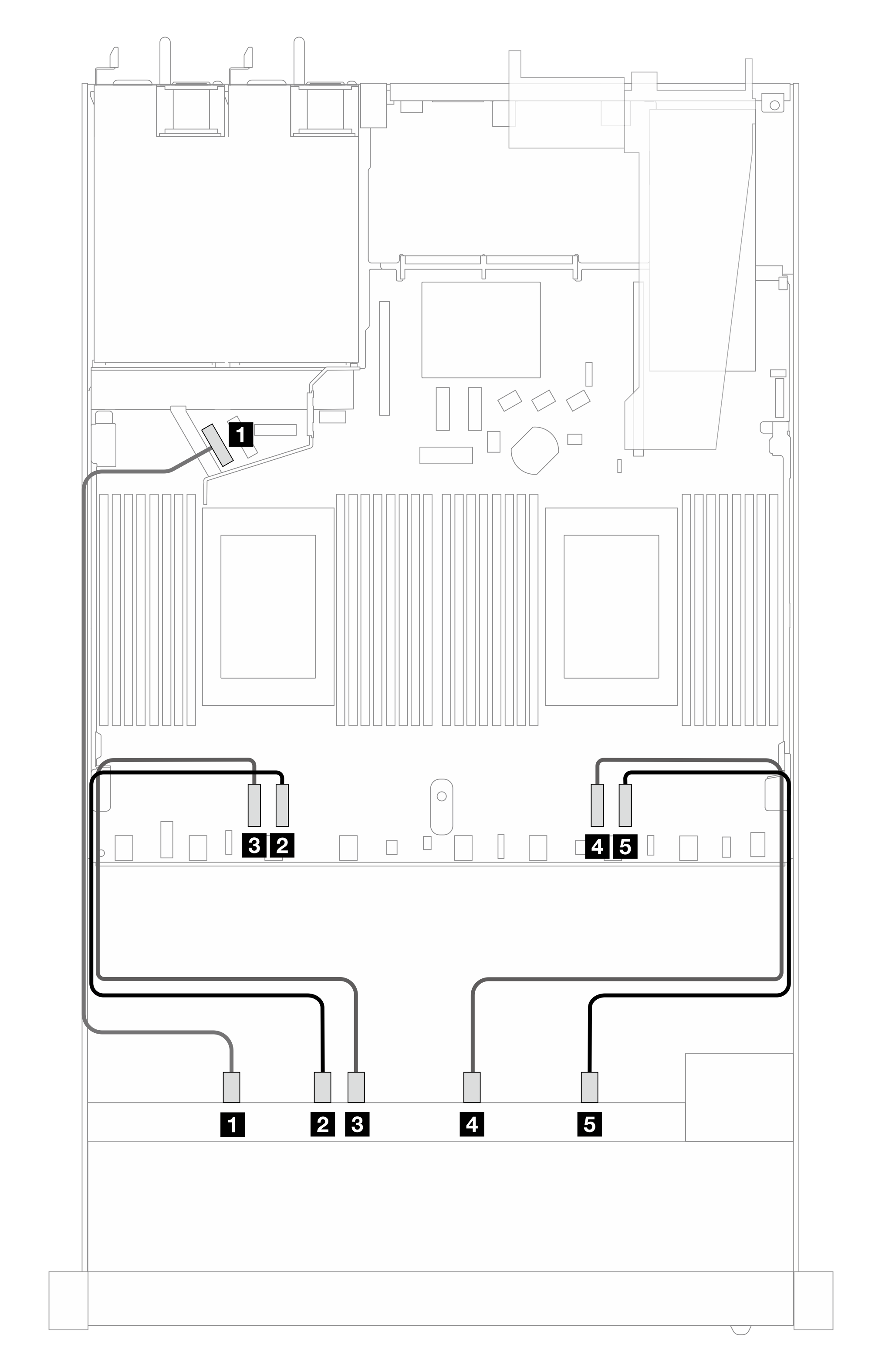
| Backplane | From | To |
|---|---|---|
| Front BP (NVMe) | 1 NVMe 0–1 | 1 PCIe 5 |
| 2 NVMe 2–3 | 2 PCIe 3 | |
| 3 NVMe 4–5 | 3 PCIe 4 | |
| 4 NVMe 6–7 | 4 PCIe 2 | |
| 5 NVMe 8–9 | 5 PCIe 1 |
Onboard cabling of 10 NVMe drives for liquid cooling (Gen 5 backplane)
Figure 2. Onboard cabling of 10 NVMe drives for liquid cooling (Gen 5 backplane)
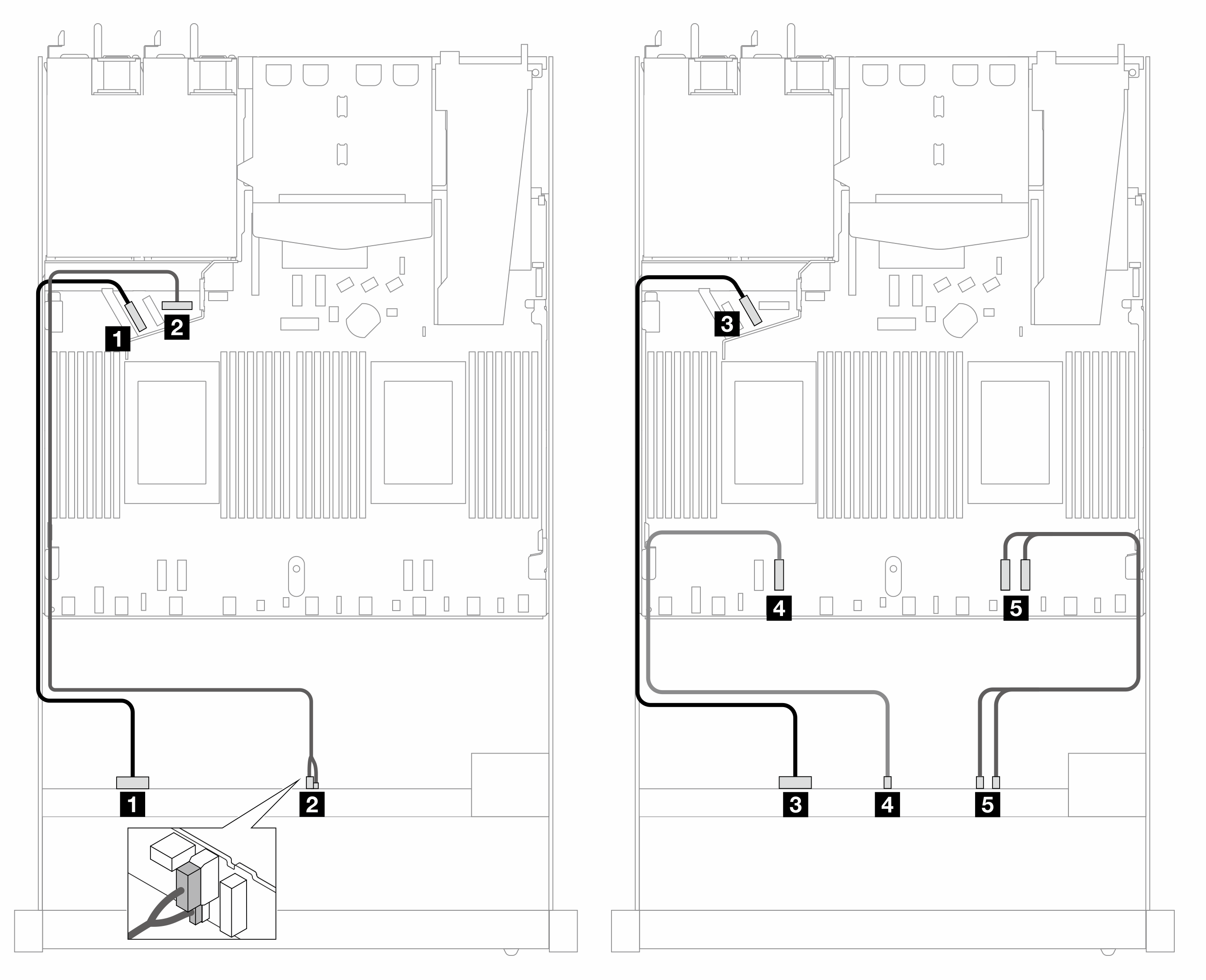
| Backplane | From | To |
|---|---|---|
| Front BP (NVMe) | 1 NVMe 0–1 | 1 PCIe 5 |
| Power | 2 Power and sideband | 2 Power port for front BP |
| Front BP (NVMe) | 3 NVMe 2–3 | 3 PCIe 6 |
| 4 NVMe 4–5 | 4 PCIe 3 | |
| 5 NVMe 6–7, 8–9 | 5 PCIe 2, 1 |
Give documentation feedback