6 x 2.5'' SAS/SATA + 4 x 2.5'' AnyBay (Gen 5)
See this section to understand the cable routing of six front SAS/SATA drives and four front AnyBay drives with 10 x 2.5'' backplane (Gen 5) installed.
To connect cables for a 7mm drive backplane, refer to 7mm drive backplane.
To connect cables for M.2 drives, refer to M.2 drive backplane.
To connect cables for rear NVMe drives, refer to Rear NVMe backplane cable routing with 10 x 2.5'' AnyBay backplane (Gen 5) installed.
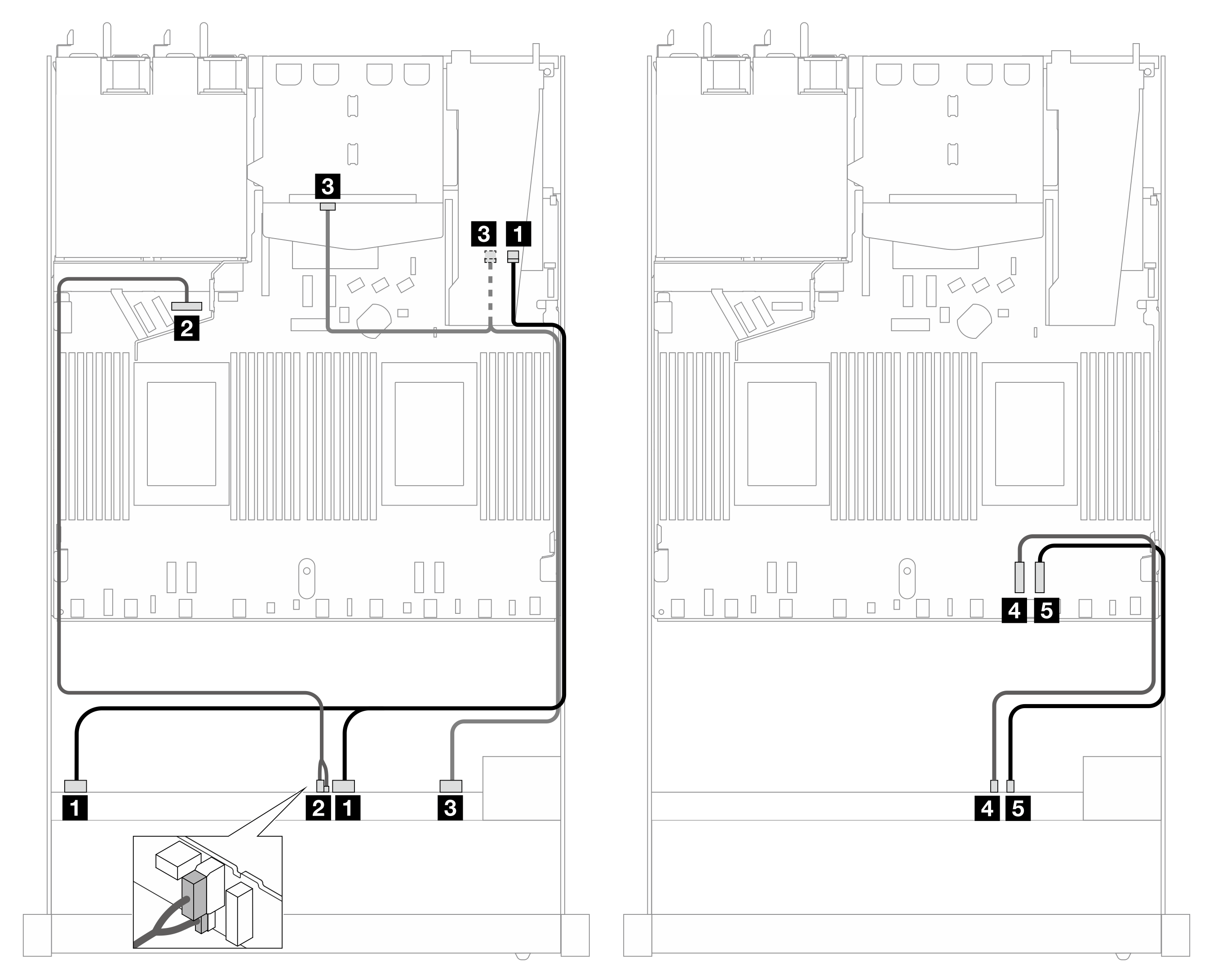
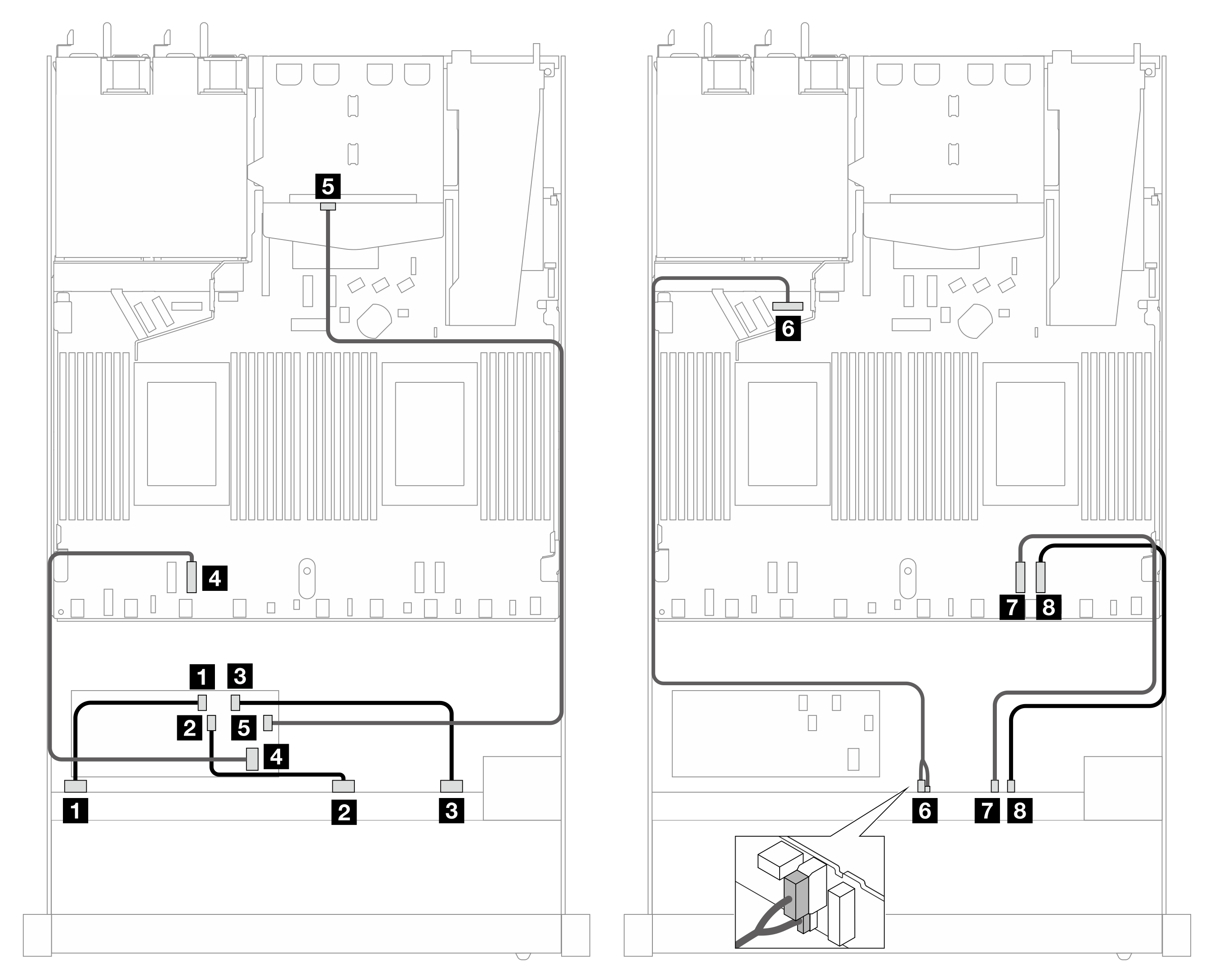
Cable routing for onboard configuration
The following illustration and table show the mapping relationship between backplane connectors and processor board connectors for onboard configuration.

| Backplane | From | To |
|---|---|---|
| Front BP (SAS) | 1 SAS 0–3 | 1 SATA 0 |
| Front BP (power) | 2 Power and sideband Note | 2 Power port for front BP |
| Front BP (SAS) | 3 SAS 4–7, 8–9 | 3 SATA 1, 2 |
| Front BP (NVMe) | 4 NVMe 6–7 | 4 PCIe 2 |
| 5 NVMe 8–9 | 5 PCIe 1 |
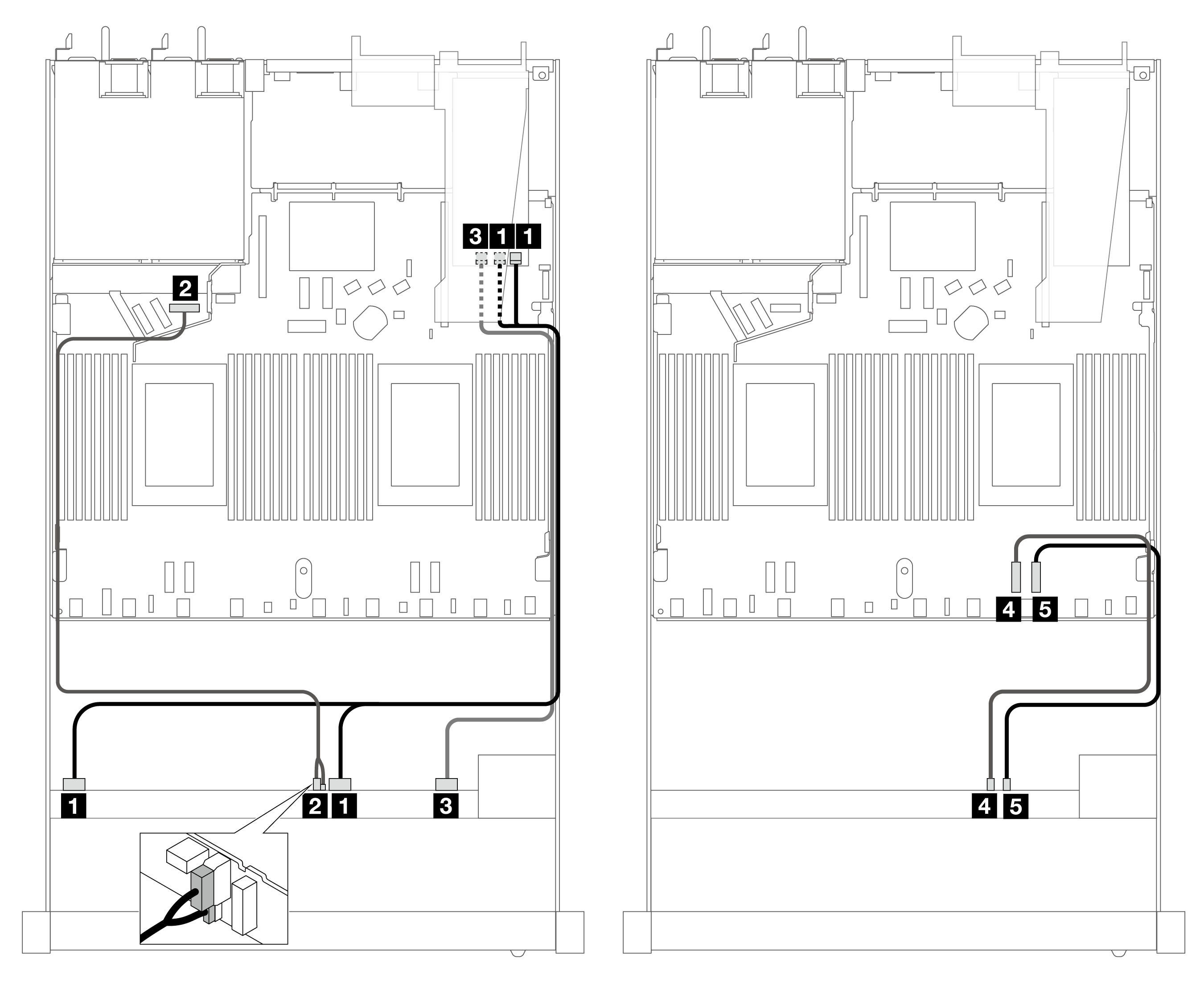
Cable routing with an SFF HBA/RAID adapter
The following tables show the mapping relationship between backplane connectors and a 16i SFF RAID adapter (Gen 3 or Gen 4).

| Backplane | From | To |
|---|---|---|
| Front BP (SAS) | 1 SAS 0–3, 4–7 | 1 C0 |
| Front BP (power) | 2 Power and sideband | 2 Power port for front BP |
| Front BP (SAS) | 3 SAS 8–9 | 3 C1 |
| Front BP (NVMe) | 4 NVMe 6–7 | 4 PCIe 2 |
| 5 NVMe 8–9 | 5 PCIe 1 |
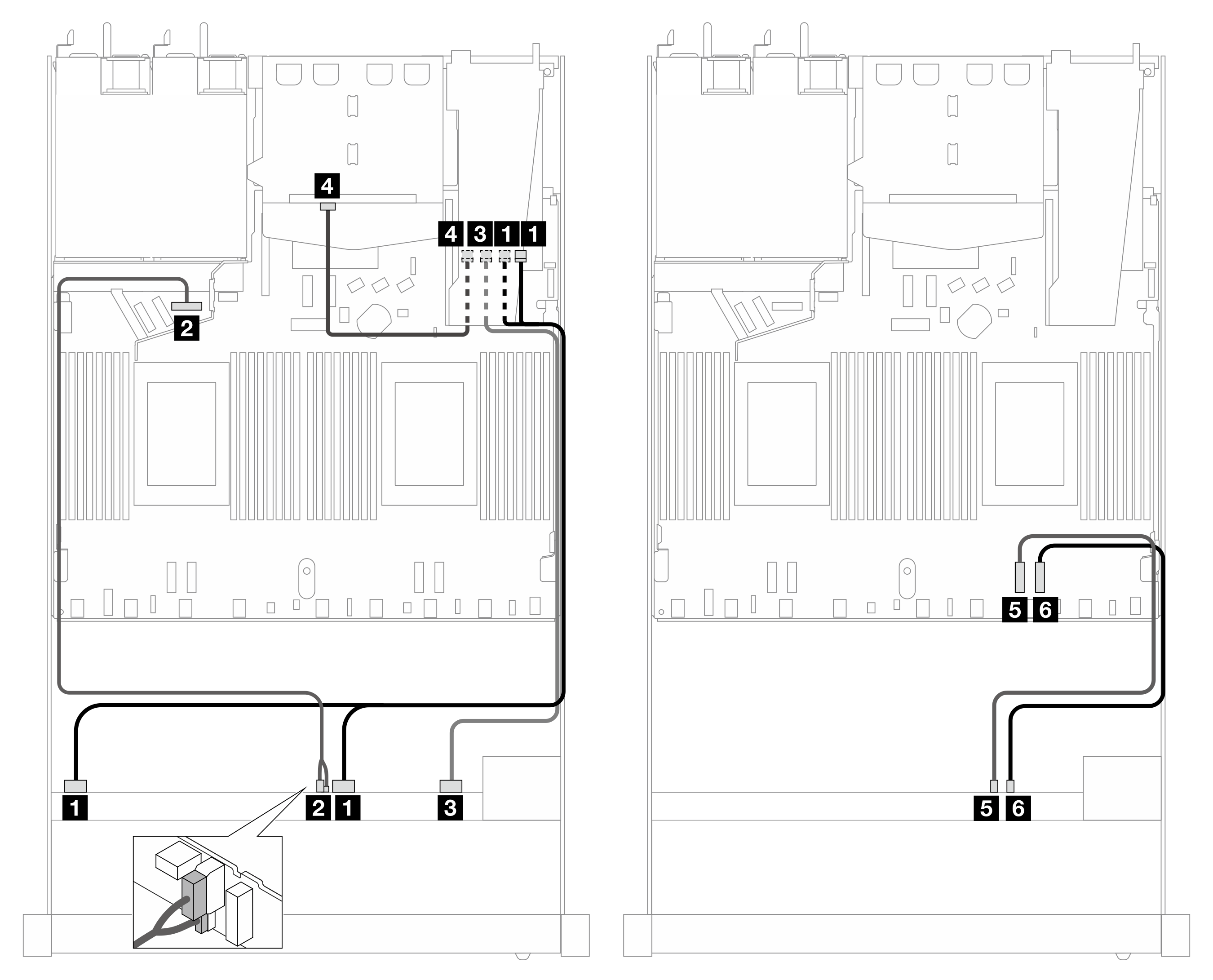
| Backplane | From | To |
|---|---|---|
| Front BP (SAS) | 1 SAS 0–3, 4–7 | 1 C0 |
| Front BP (power) | 2 Power and sideband | 2 Power port for front BP |
| Front and rear BP (SAS) | 3 SAS 8–9, SAS (rear) | 3 C1 |
| Front BP (NVMe) | 4 NVMe 6–7 | 4 PCIe 2 |
| 5 NVMe 8–9 | 5 PCIe 1 |
| Backplane | From | To |
|---|---|---|
| Front BP (SAS) | 1 SAS 0–3, 4–7 | 1 C0, C1 |
| Front BP (power) | 2 Power and sideband | 2 Power port for front BP |
| Front BP (SAS) | 3 SAS 8–9 | 3 C2 |
| Front BP (NVMe) | 4 NVMe 6–7 | 4 PCIe 2 |
| 5 NVMe 8–9 | 5 PCIe 1 |
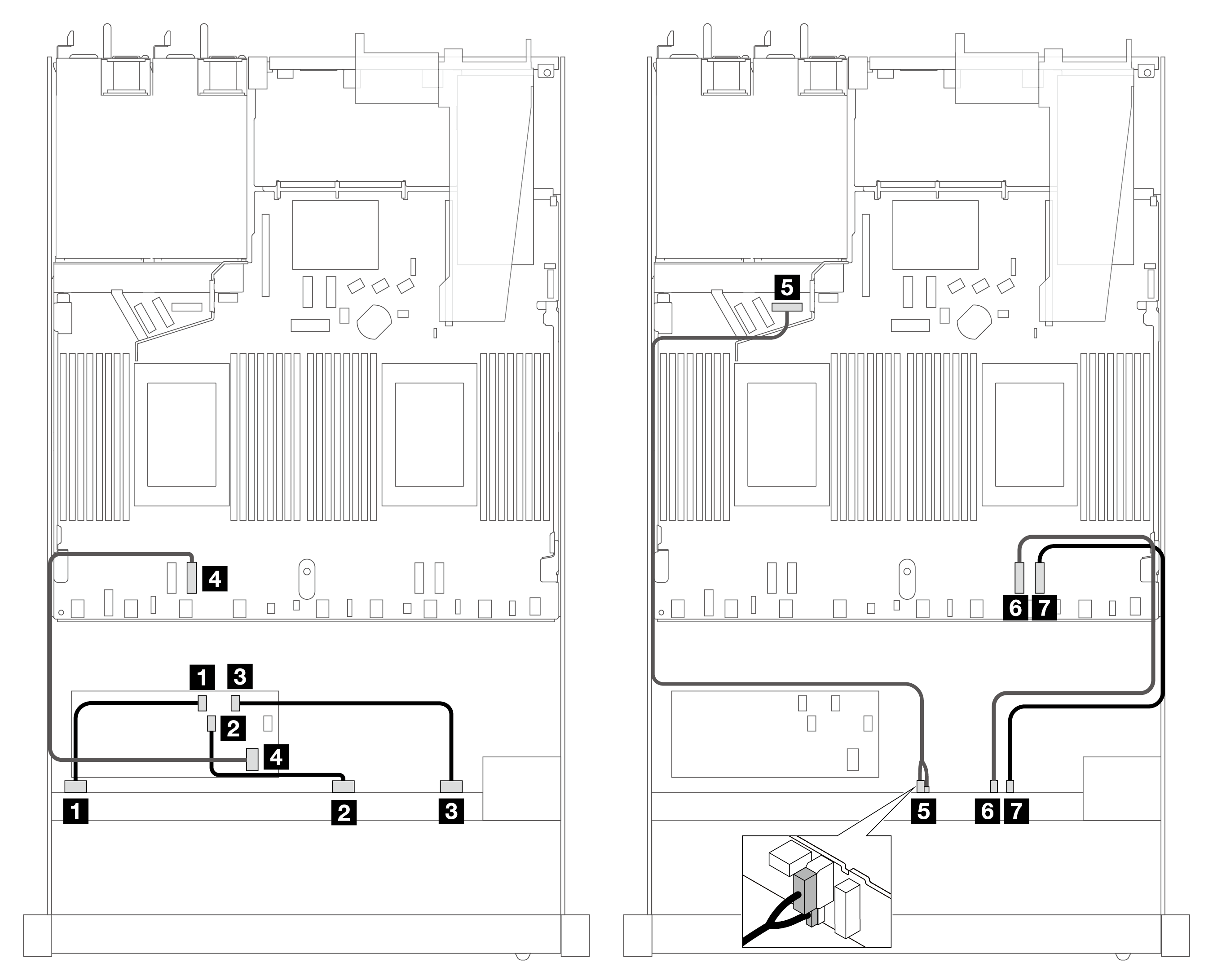
| Backplane | From | To |
|---|---|---|
| Front BP (SAS) | 1 SAS 0–3, 4–7 | 1 C0 |
| Front BP (power) | 2 Power and sideband | 2 Power port for front BP |
| Front BP (SAS) | 3 SAS 8–9 | 3 C1 |
| Rear BP (SAS) | 4 SAS (rear) | 4 C2 |
| Front BP (NVMe) | 5 NVMe 6–7 | 5 PCIe 2 |
| 6 NVMe 8–9 | 6 PCIe 1 |
Cable routing with a CFF HBA/RAID adapter
The following tables show the mapping relationship between backplane connectors and a CFF HBA/RAID adapter.
| Backplane/adapter | From | To |
|---|---|---|
| Front BP (SAS) | 1 SAS 0–3 | 1 C0 |
| 2 SAS 4–7 | 2 C1 | |
| 3 SAS 8–9 | 3 C2 | |
| CFF RAID adapter | 4 MB input | 4 PCIe 3 |
| Front BP (power) | 5 Power and sideband | 5 Power port for front BP |
| Front BP (NVMe) | 6 NVMe 6–7 | 6 PCIe 2 |
| 7 NVMe 8–9 | 7 PCIe 1 |
| Backplane/adapter | From | To |
|---|---|---|
| Front BP (SAS) | 1 SAS 0–3 | 1 C0 |
| 2 SAS 4–7 | 2 C1 | |
| 3 SAS 8–9 | 3 C2 | |
| CFF RAID adapter | 4 MB input | 4 PCIe 3 |
| 5 C3 | 5 SAS (rear) | |
| Front BP (power) | 6 Power and sideband | 6 Power port for front BP |
| Front BP (NVMe) | 7 NVMe 6–7 | 7 PCIe 2 |
| 8 NVMe 8–9 | 8 PCIe 1 |