12 x 2.5'' NVMe (Gen 5)
See this section to understand the cable routing of 12 front NVMe drives with 10 x 2.5'' backplane (Gen 5) installed.
To connect cables for a 7mm drive backplane, refer to 7mm drive backplane.
To connect cables for M.2 drives, refer to M.2 drive backplane.
Cable routing for onboard configuration
The following table shows the mapping relationship between backplane connectors and system board connectors for onboard configuration.
Figure 1. Cable routing for onboard configuration of 12 x 2.5'' NVMe front drives
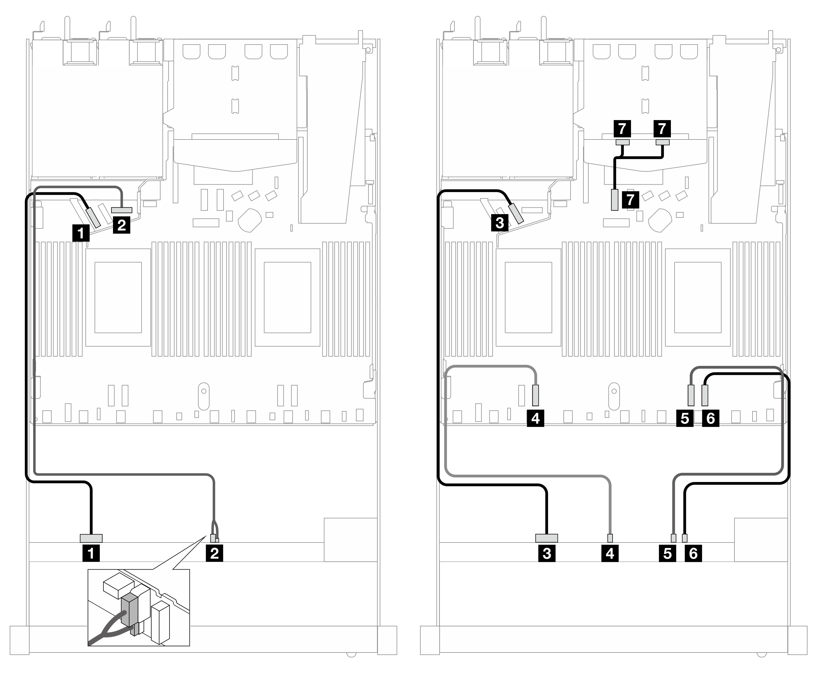
| Backplane | From | To |
|---|---|---|
| Front BP (NVMe) | 1 NVMe 0–1 | 1 PCIe 5 |
| Front BP (power) | 2 Power and sideband | 2 Power port for front BP |
| Front BP (NVMe) | 3 NVMe 2–3 | 3 PCIe 6 |
| 4 NVMe 4–5 | 4 PCIe 3 | |
| 5 NVMe 6–7 | 5 PCIe 2 | |
| 6 NVMe 8–9 | 6 PCIe 1 | |
| Rear BP (NVMe) | 7 NVMe 0, 1(rear) | 7 PCIe 7 |
Give documentation feedback