Install a PCIe adapter and riser assembly
Use this information to install a PCIe adapter and riser assembly.


The ThinkSystem Broadcom 57454 10/25GbE SFP28 4-port PCIe Ethernet Adapter_Refresh (V2) requires a full-height bracket and must be installed in a full-height slot.
- ThinkSystem Xilinx Alveo U50 Data Center Accelerator Adapter is supported only when the following requirement are met:
Only for server modules installed with four 3.5-inch SAS/SATA drives, four 3.5-inch SAS/SATA/NVMe drives, eight 2.5-inch SAS/SATA drives, or ten 2.5-inch SAS/SATA/NVMe drives.
For server models installed with one CPU, only one adapter is supported and must be installed in PCIe slot 1.
For server models installed with two CPUs, up to two adapters are supported and must be installed in PCIe slot 1 and slot 3.
The maximum supported processor TDP is 165 watts
The maximum operating temperature is 30°C.
No fan fails.
Touch the static-protective package that contains the new PCIe adapter to any unpainted surface on the outside of the server. Then, take the new PCIe adapter out of the package and place it on a static-protective surface.
Touch the static-protective package that contains the new riser assembly to any unpainted surface on the outside of the server. Then, take the new riser assembly out of the package and place it on a static-protective surface.
Locate the correct PCIe slot for the PCIe adapter. For information about the PCIe slots and supported PCIe adapters, see Rear view.
To install a PCIe adapter and riser assembly, complete the following steps:
- Install the PCIe adapter into the riser assembly.
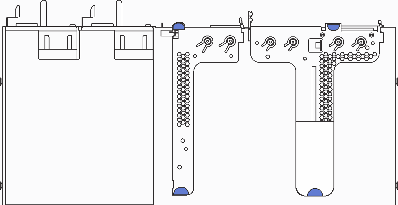
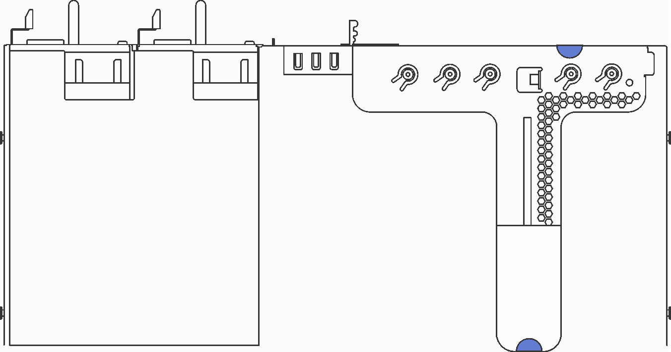
Table 1. PCIe adapter installation Figure 4. Riser 1 assembly (LP+LP)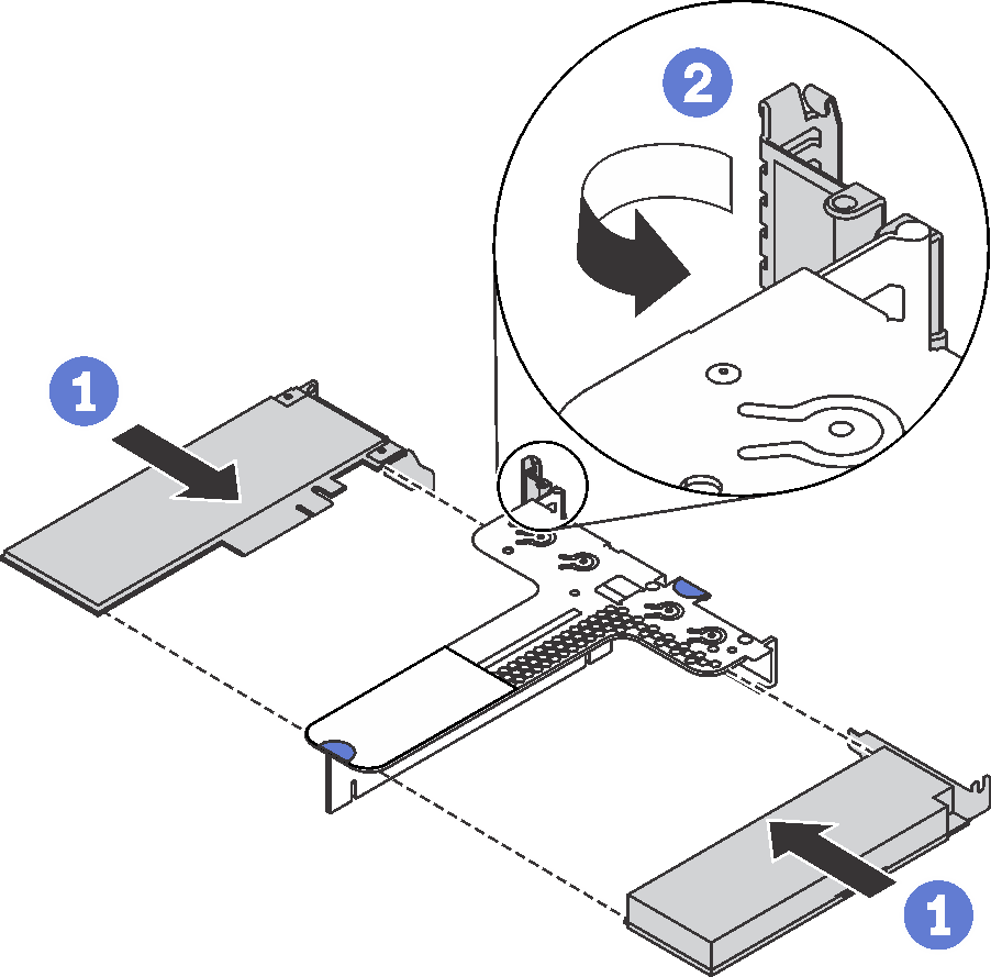 Figure 5. Riser 1 assembly (LP+FHHL)
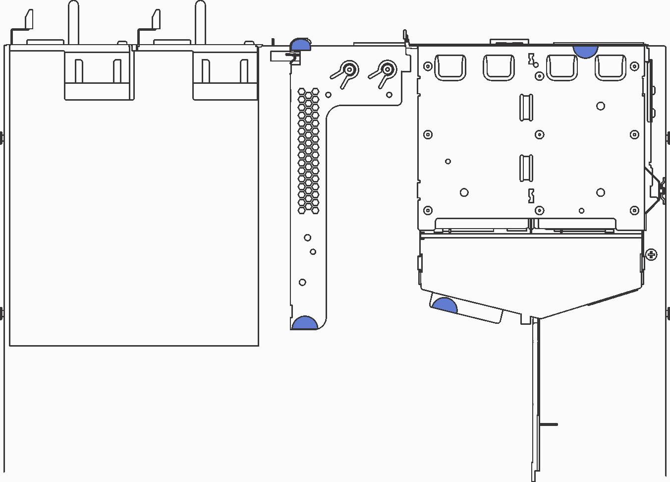
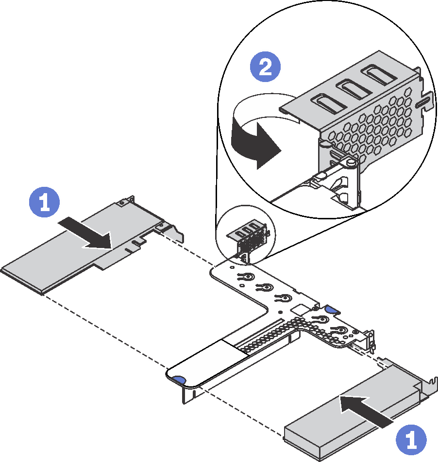 Figure 6. Riser 2 assembly (LP)
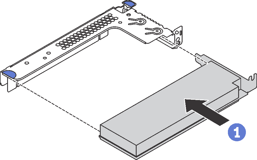
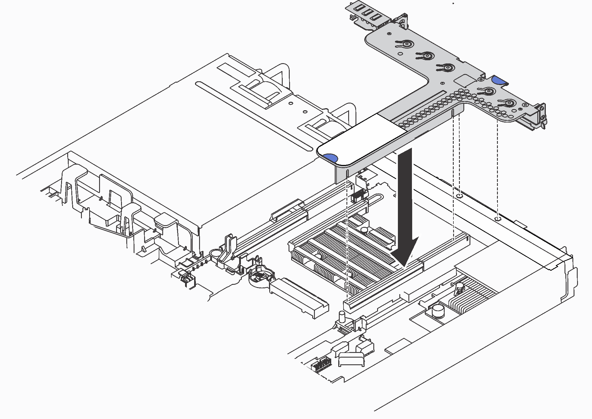
- Position the riser assembly on the chassis. Align the two pins on the bracket with the two holes in the chassis and align the riser card with the riser slot on the system board. Then, carefully press the riser assembly straight down into the slot until it is fully seated.NoteThe riser assembly you want to install might be different from the following illustration, but the installation method is the same.Figure 7. Riser assembly installation