Remove the external diagnostics cable (4 x 3.5'' chassis)
Use this information to remove the external diagnostics cable.
Figure 1. A front view with the cable installed 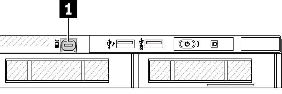 1 The external diagnostics cable connector | Figure 2. A front view with a filler installed 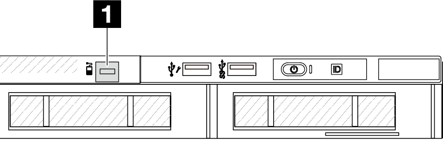 1 A filler for external diagnostics cable connector |
About this task
The following illustrates how to remove the external diagnostics cable from the chassis.
Read Installation Guidelines and Safety inspection checklist to ensure that you work safely.
Power off the server and peripheral devices and disconnect the power cords and all external cables. See Power off the server.
Prevent exposure to static electricity, which might lead to system halt and loss of data, by keeping static-sensitive components in their static-protective packages until installation, and handling these devices with an electrostatic-discharge wrist strap or other grounding system.
Procedure
- Disconnect the external diagnostics cable, the front I/O cable, and the USB cable from the processor board. Figure 3. Disconnecting cable from the system board assembly
- To get a better view of the cable connector latch inside the chassis, remove the front I/O module first.Figure 4. Front I/O module removal
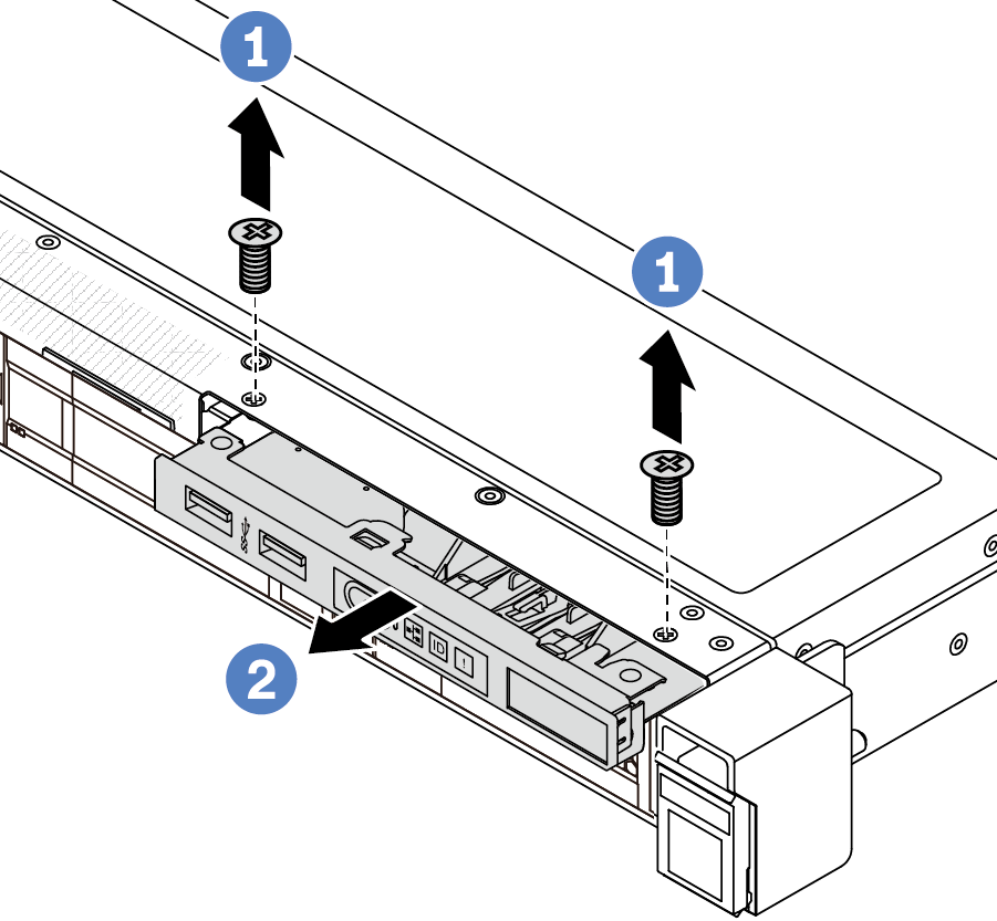
 Remove the screws that secure the front I/O module.
 Slide the front I/O module out of the front chassis.
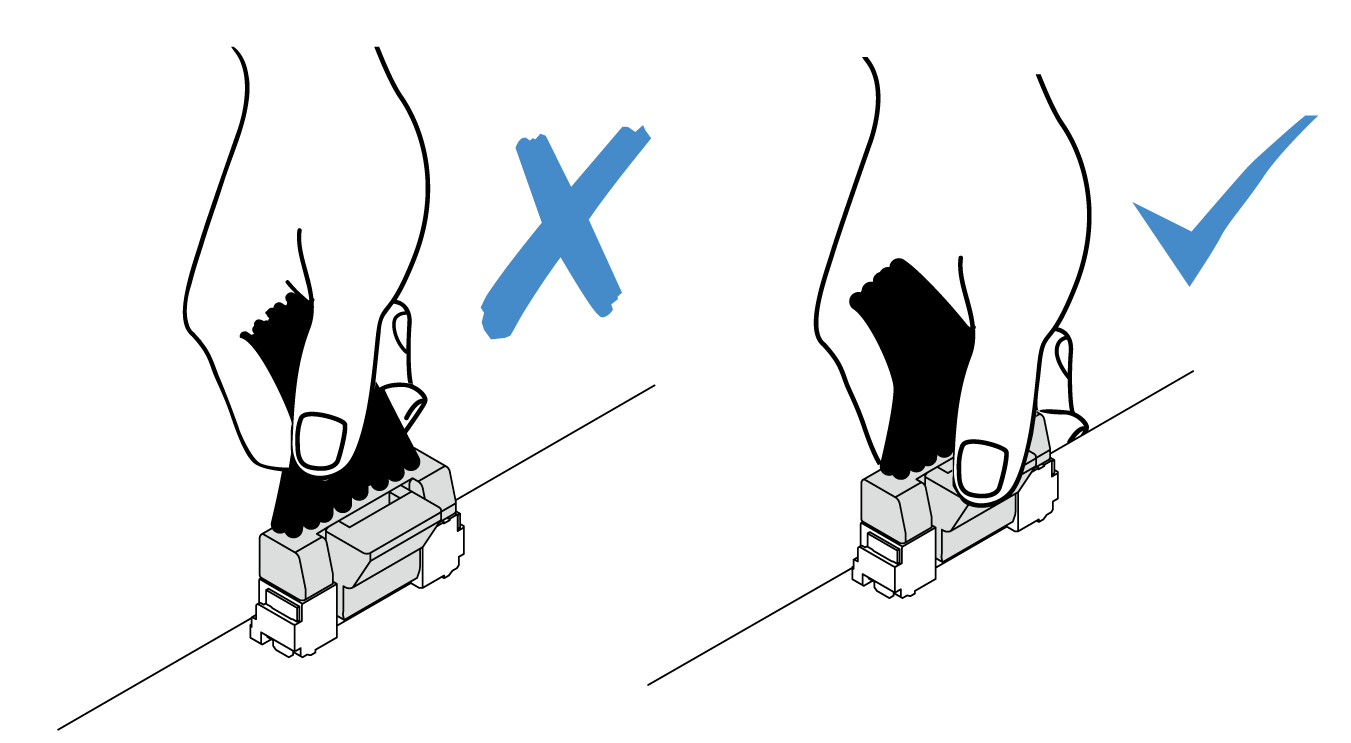
- Remove the external diagnostics cable.Figure 5. Removal of the external diagnostics cable
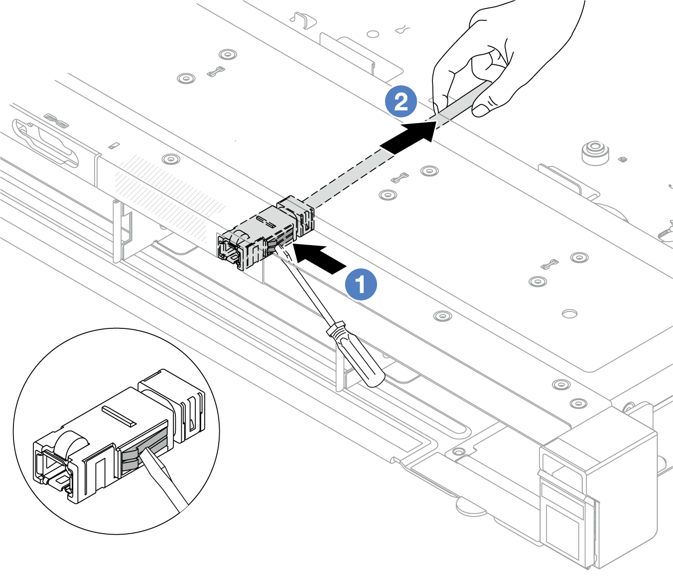
- Poke the connector latch with the tip of a flat-blade screwdriver (3 or 4 mm) to disengage the connector from the chassis.
- Pull out the cable from the back side.
- Install the front I/O module back to the chassis.Figure 6. Front I/O module installation
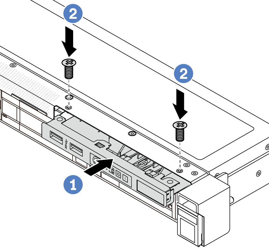
- Insert the front I/O module into the front chassis.
- Install the screws to secure the front I/O module in place.
After you finish
If you are instructed to return the component or optional device, follow all packaging instructions, and use any packaging materials for shipping that are supplied to you.
Demo video