Follow the instructions in this section to learn how to do cable routing for E3.S drive backplanes.
According to the configuration, see the corresponding section for the E3.S drive backplane cable routing:
| Backplane 1 | Backplane 2 |
| |
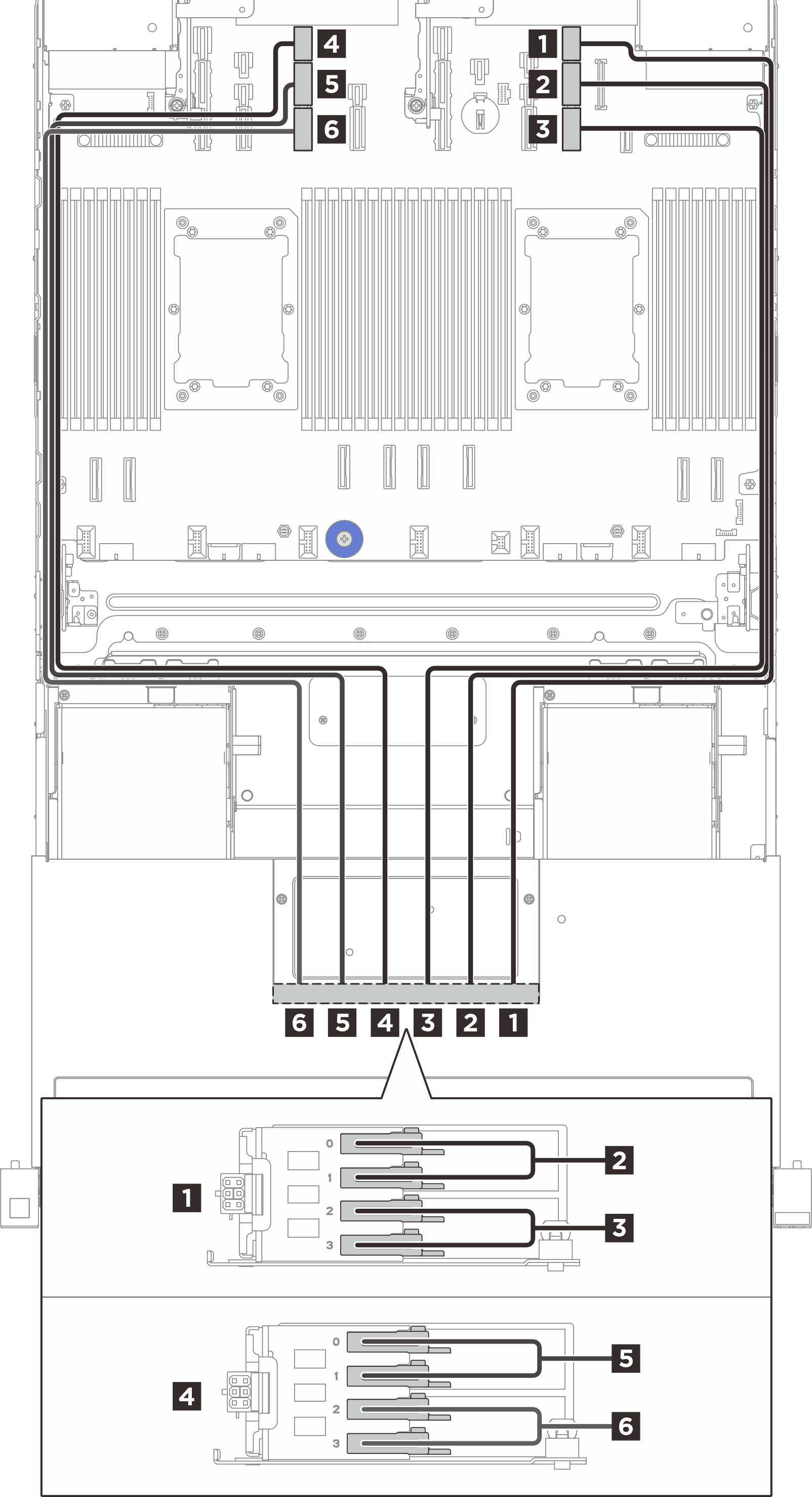
| From (E3.S backplanes) | Cable wall | To (processor board) | Cable length |
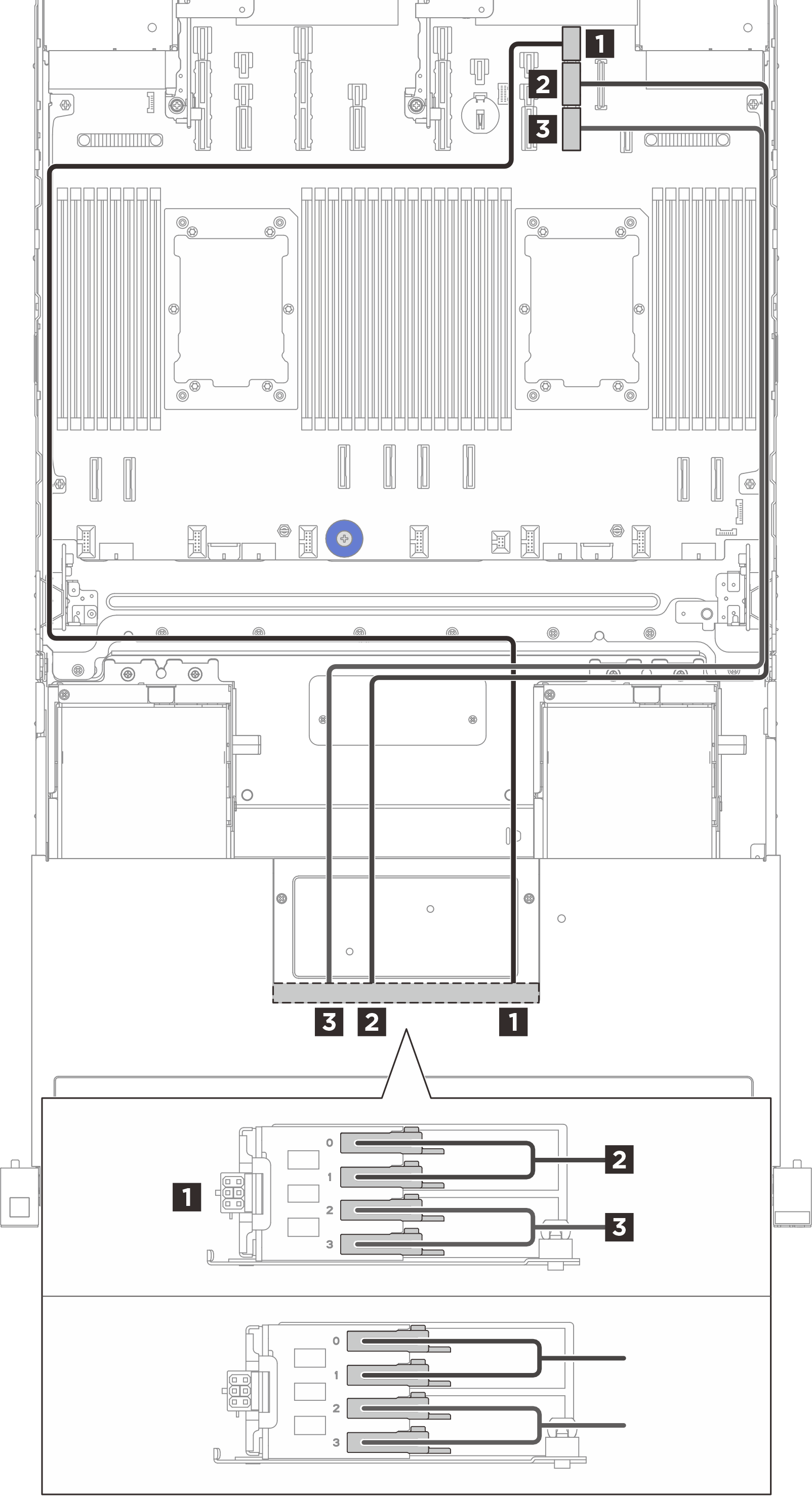
| 1 (BP1) power connector | Left cable wall | 1 Power connector 9 | 1200 mm |
| 2 (BP1) Bay 0, 1 | Right cable wall | 2 PCIe connector 9A | 850 mm |
| 3 (BP1) Bay 2, 3 | Right cable wall | 3 PCIe connector 9B | 850 mm |
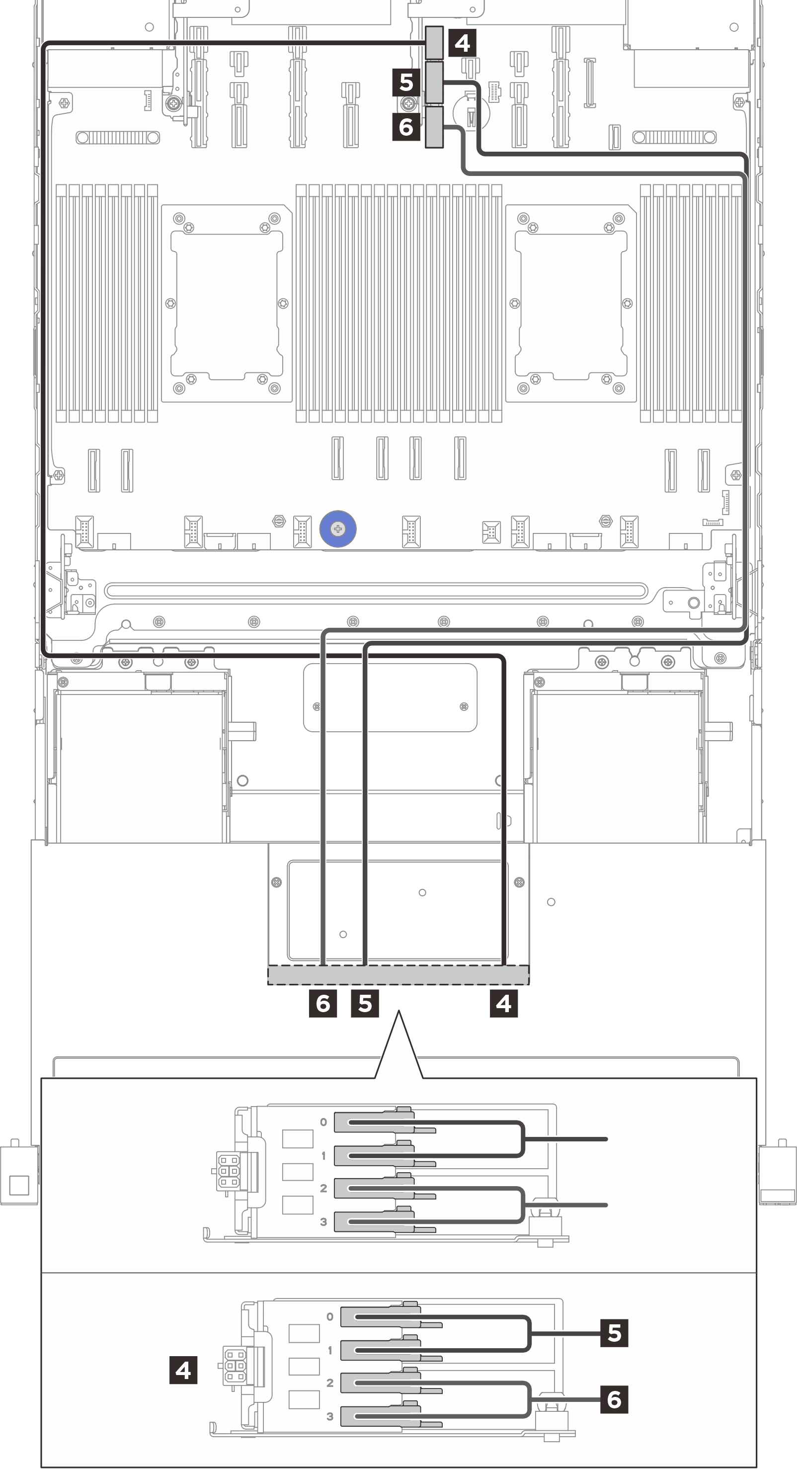
| 4 (BP2) power connector | Left cable wall | 4 Power connector 11 | 1200 mm |
| 5 (BP2) Bay 0, 1 | Right cable wall | 5 PCIe connector 11A | 850 mm |
| 6 (BP2) Bay 2, 3 | Right cable wall | 6 PCIe connector 11B | 850 mm |
| Backplane 1 | Backplane 2 |
| |
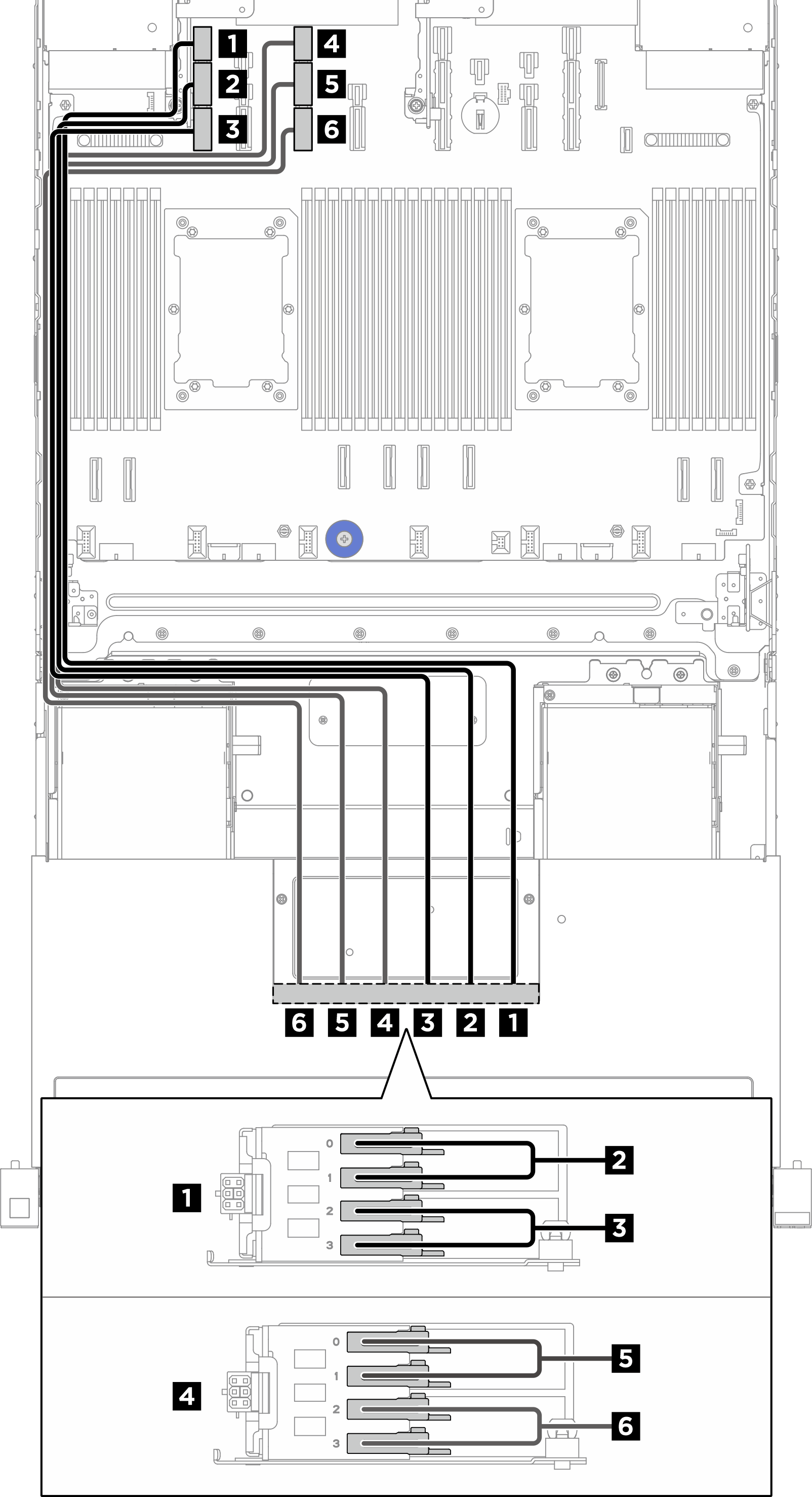
| From (E3.S backplanes) | Cable wall | To (processor board) | Cable length |
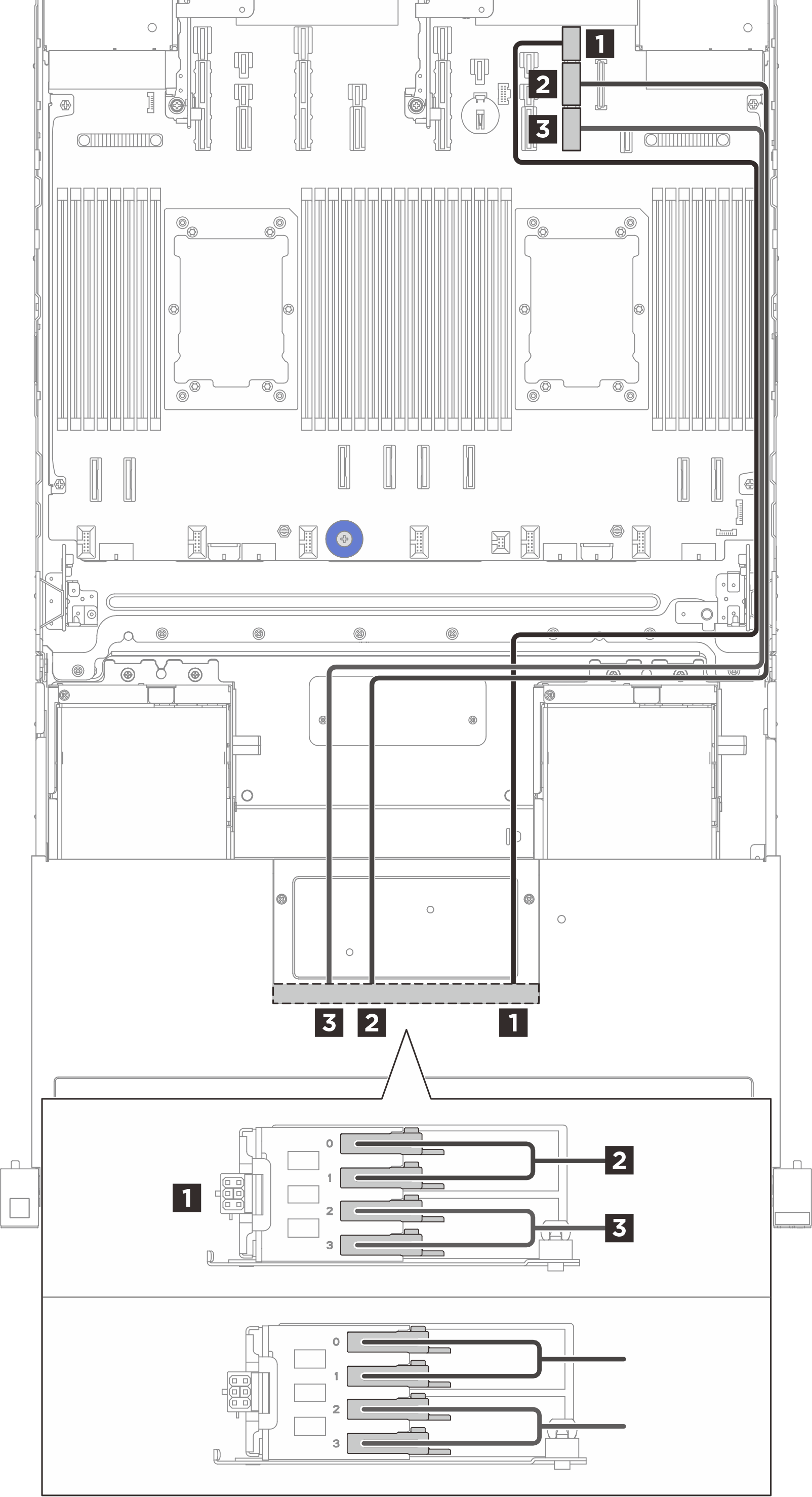
| 1 (BP1) power connector | Right cable wall | 1 Power connector 9 | 900 mm |
| 2 (BP1) Bay 0, 1 | Right cable wall | 2 PCIe connector 9A | 850 mm |
| 3 (BP1) Bay 2, 3 | Right cable wall | 3 PCIe connector 9B | 850 mm |
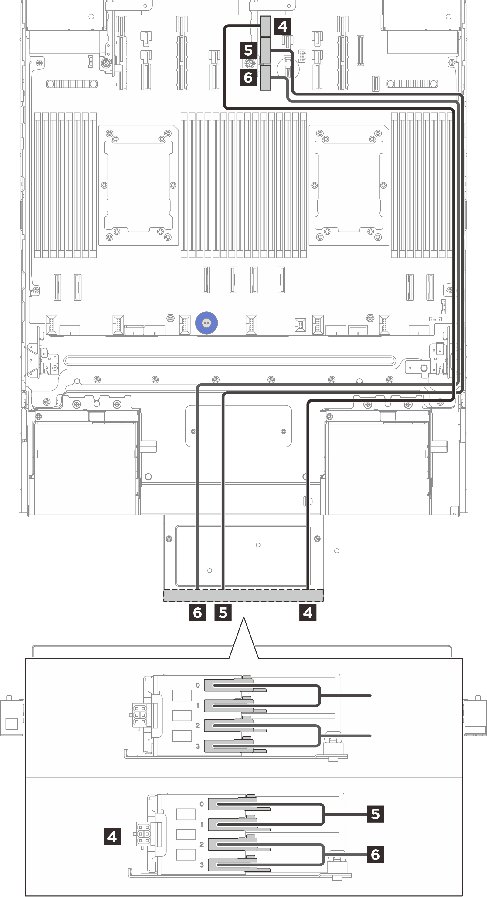
| 4 (BP2) power connector | Right cable wall | 4 Power connector 11 | 900 mm |
| 5 (BP2) Bay 0, 1 | Right cable wall | 5 PCIe connector 11A | 850 mm |
| 6 (BP2) Bay 2, 3 | Right cable wall | 6 PCIe connector 11B | 850 mm |
|
| From (E3.S backplanes) | Cable wall | To (processor board) | Cable length |
| 1 (BP1) power connector | Right cable wall | 1 Power connector 9 | 900 mm |
| 2 (BP1) Bay 0, 1 | Right cable wall | 2 PCIe connector 9A | 850 mm |
| 3 (BP1) Bay 2, 3 | Right cable wall | 3 PCIe connector 9B | 850 mm |
| 4 (BP2) power connector | Left cable wall | 4 Power connector 13 | 900 mm |
| 5 (BP2) Bay 0, 1 | Left cable wall | 5 PCIe connector 13A | 850 mm |
| 6 (BP2) Bay 2, 3 | Left cable wall | 6 PCIe connector 13B | 850 mm |
|
| From (E3.S backplanes) | Cable wall | To (processor board) | Cable length |
| 1 (BP1) power connector | Left cable wall | 1 Power connector 15 | 900 mm |
| 2 (BP1) Bay 0, 1 | Left cable wall | 2 PCIe connector 15A | 850 mm |
| 3 (BP1) Bay 2, 3 | Left cable wall | 3 PCIe connector 15B | 850 mm |
| 4 (BP2) power connector | Left cable wall | 4 Power connector 13 | 900 mm |
| 5 (BP2) Bay 0, 1 | Left cable wall | 5 PCIe connector 13A | 850 mm |
| 6 (BP2) Bay 2, 3 | Left cable wall | 6 PCIe connector 13B | 850 mm |
For the front M.2 backplane cable routing, see Front M.2 boot backplane and controller board cable routing.
|
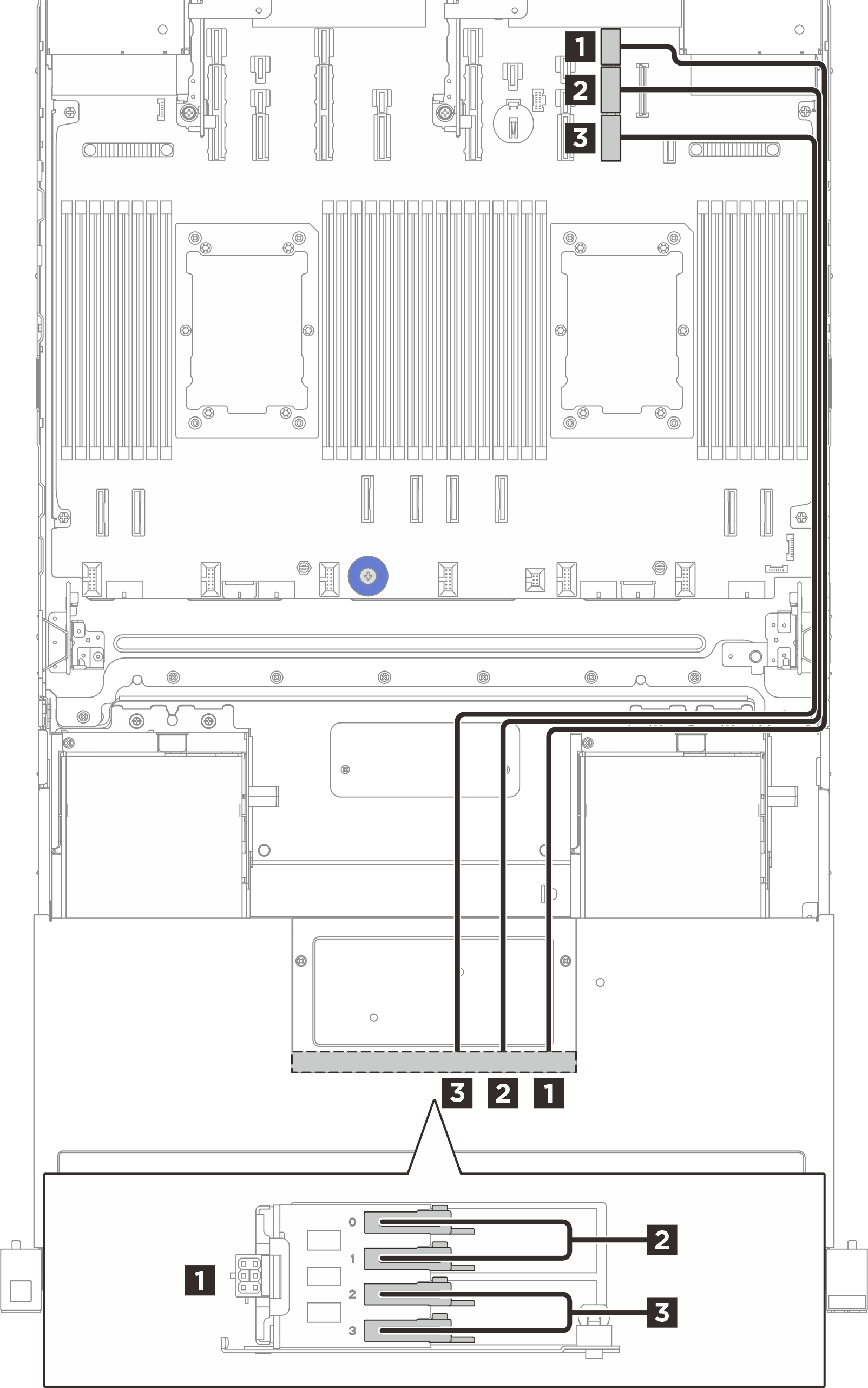
| From (E3.S backplane) | Cable wall | To (processor board) | Cable length |
| 1 (BP1) power connector | Right cable wall | 1 Power connector 9 | 900 mm |
| 2 (BP1) Bay 0, 1 | Right cable wall | 2 PCIe connector 9A | 850 mm |
| 3 (BP1) Bay 2, 3 | Right cable wall | 3 PCIe connector 9B | 850 mm |