Install a front 2.5-inch drive backplane
Follow instructions in this section to install a front 2.5-inch drive backplane. The procedure must be executed by a trained technician.
About this task
Attention
- Read Installation Guidelines and Safety inspection checklist to ensure that you work safely.
- Touch the static-protective package that contains the component to any unpainted metal surface on the server; then, remove it from the package and place it on a static-protective surface.
- Power off the server and peripheral devices and disconnect the power cords and all external cables. See Power off the server.
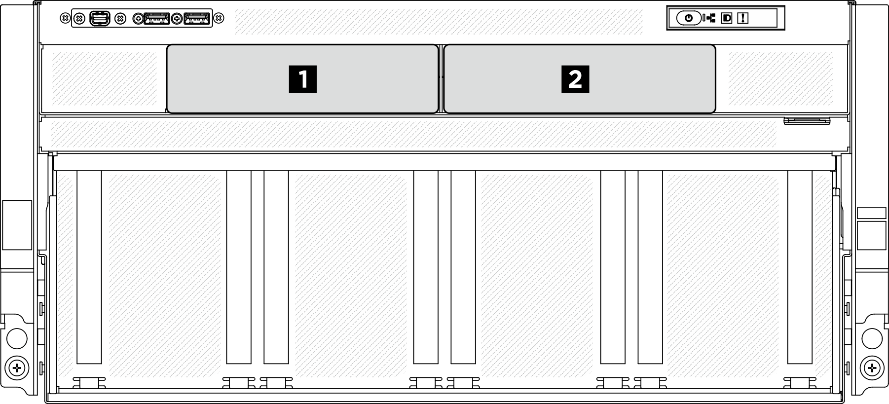
- The server supports up to two front 2.5-inch drive backplanes with the following corresponding drive backplane numbering.Figure 1. Front 2.5-inch drive backplane numbering
Firmware and driver download: You might need to update the firmware or driver after replacing a component.
Go to Drivers and Software download website for ThinkSystem SR780a V3 to see the latest firmware and driver updates for your server.
Go to Update the firmware for more information on firmware updating tools.
Procedure
 Align the 2.5-inch drive backplane with the two screw holes on the bracket; then, fasten the two M3 screws (PH2, 2 x M3, 0.5 newton-meters, 4.3 inch-pounds) to secure the drive backplane to the bracket.Figure 2. Front 2.5-inch drive backplane installation
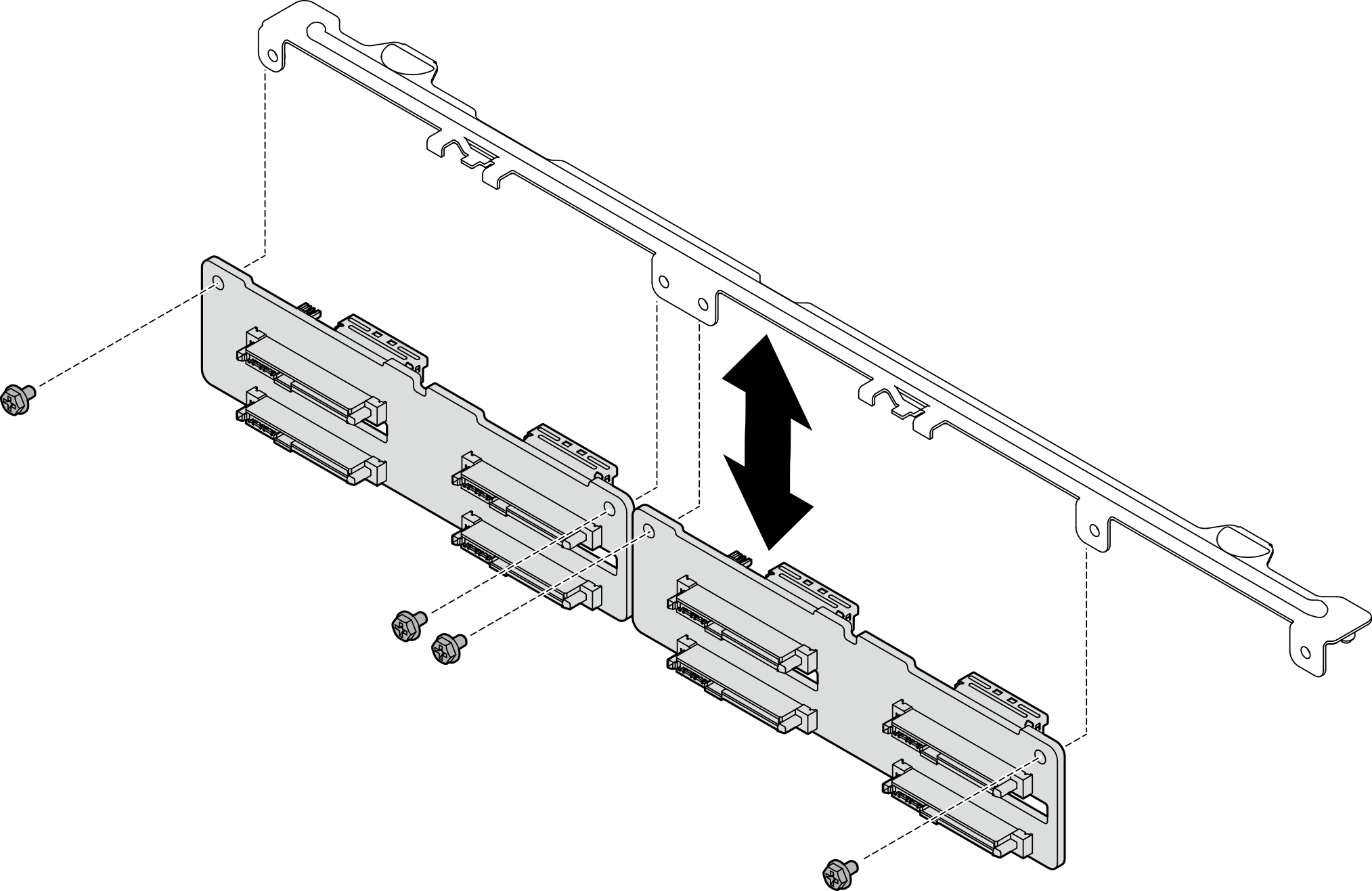
 Align the pins on the backplane bracket with the slot on the drive cage; then, lower the backplane into the drive cage. Press the pins on the bracket to make them pass through the holes on the drive cage, and ensure the backplanes sit securely on the tabs.Figure 3. Front 2.5-inch drive backplane bracket installation
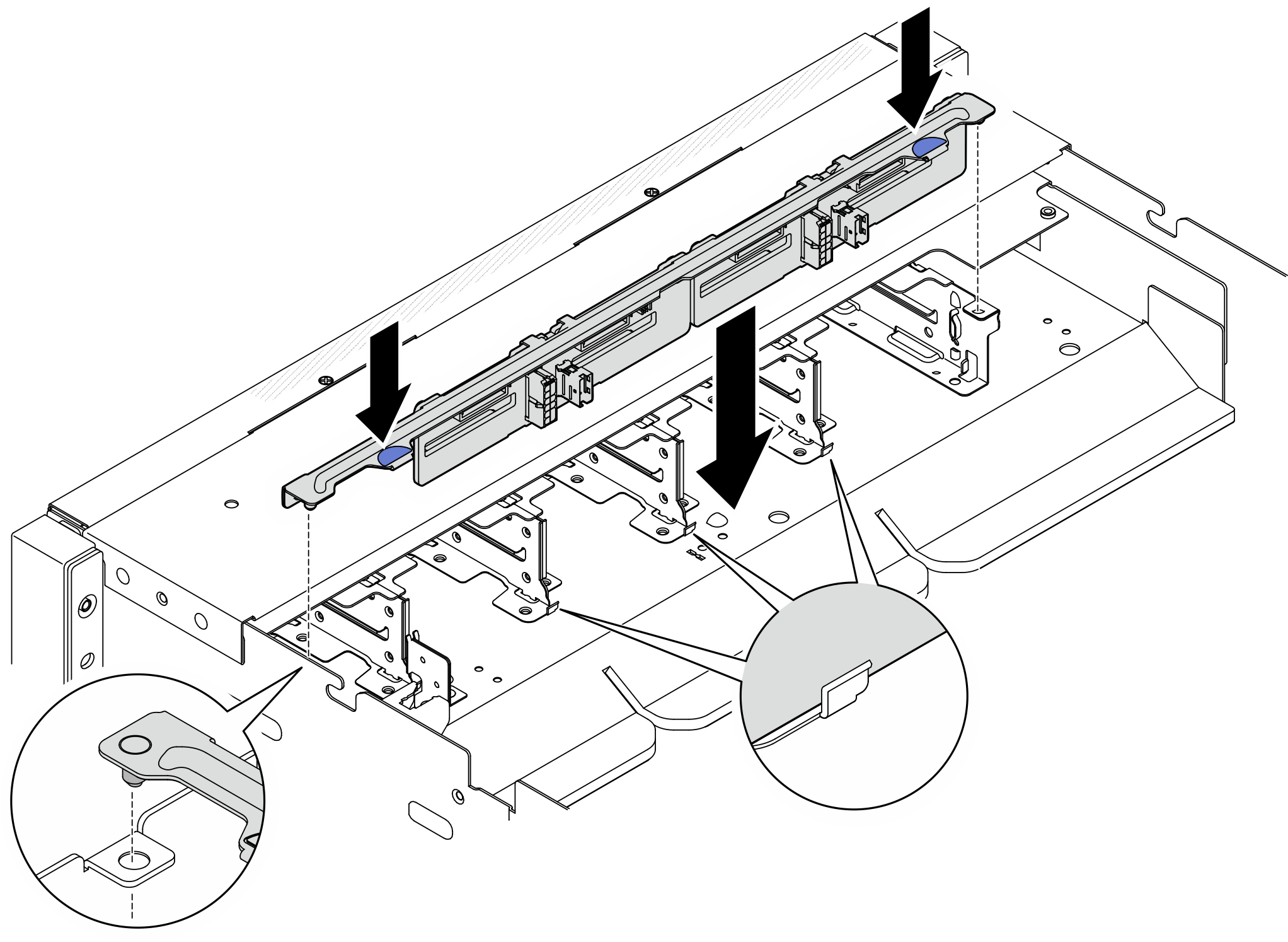
- If necessary, attach the labels to both ends of the cable.
- Attach the white space portion of the label to one end of the cable.
- Wrap the label around the cable and attach it to the white space portion.
- Repeat to attach the other label to the opposite end of the cable.
Figure 4. Label application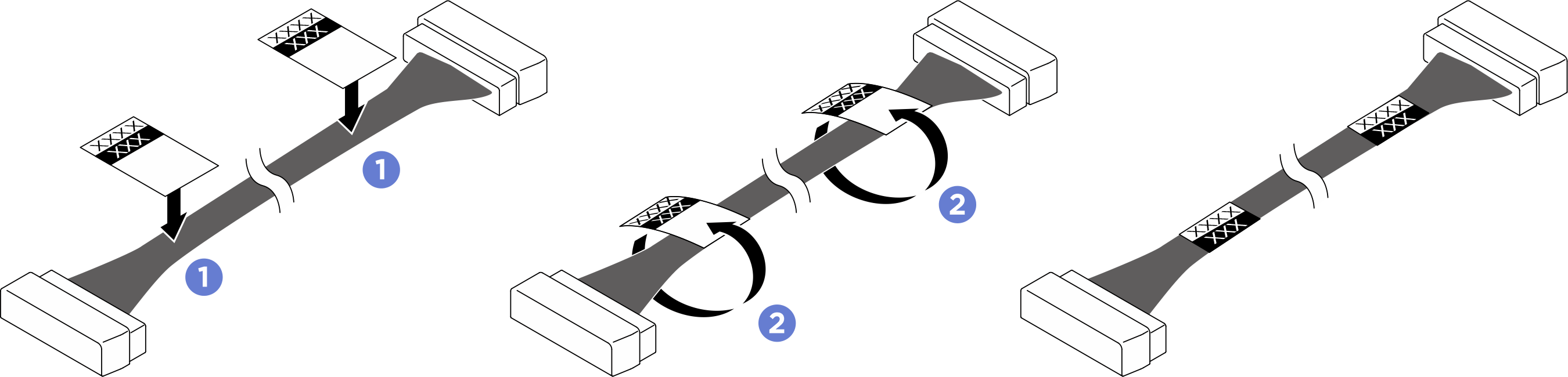 NoteSee the table below to identify the corresponding labels for the cable.
From To Label Backplane 1: NVMe connector 0-1 PCIe switch board: NVMe connector 1 (NVME1) - NVME 0-1
- NVME 1
Backplane 1: Power connector Power distribution board: Backplane 1 power connector (BP1 PWR) - BP1 PWR
- BP1 PWR
Backplane 1: NVMe connector 2-3 PCIe switch board: NVMe connector 3 (NVME3) - NVME 2-3
- NVME 3
Backplane 2: NVMe connector 0-1 PCIe switch board: NVMe connector 5 (NVME5) - NVME 0-1
- NVME 5
Backplane 2: Power connector Power distribution board: Backplane 2 power connector (BP2 PWR) - BP2 PWR
- BP2 PWR
Backplane 2: NVMe connector 2-3 PCIe switch board: NVMe connector 7 (NVME7) - NVME 2-3
- NVME 7
After you finish
- Reinstall all the 2.5-inch hot-swap drives or drive bay fillers (if any) into the drive bays. See Install a 2.5-inch hot-swap drive.
- Reinstall the front top cover. See Install the front top cover.
- Complete the parts replacement. See Complete the parts replacement.
Give documentation feedback