Install the DPU air baffle
Follow instructions in this section to install the DPU air baffle. The procedure must be executed by a trained technician.
About this task
Attention
- Read Installation Guidelines and Safety inspection checklist to ensure that you work safely.
- Power off the server and peripheral devices and disconnect the power cords and all external cables. See Power off the server.
- If the server is installed in a rack, slide the server out on its rack slide rails to gain access to the top cover, or remove the chassis from the rack. See Remove the server from rack.
- Two people and one lifting device on site that can support up to 400 lb (181 kg) are required to perform this procedure. If you do not already have a lifting device available, Lenovo offers the Genie Lift GL-8 material lift that can be purchased at Data Center Solution Configurator. Make sure to include the Foot-release brake and the Load Platform when ordering the Genie Lift GL-8 material lift.
- Install the DPU air baffle when NVIDIA BlueField-3 is installed in the riser slot.
Procedure
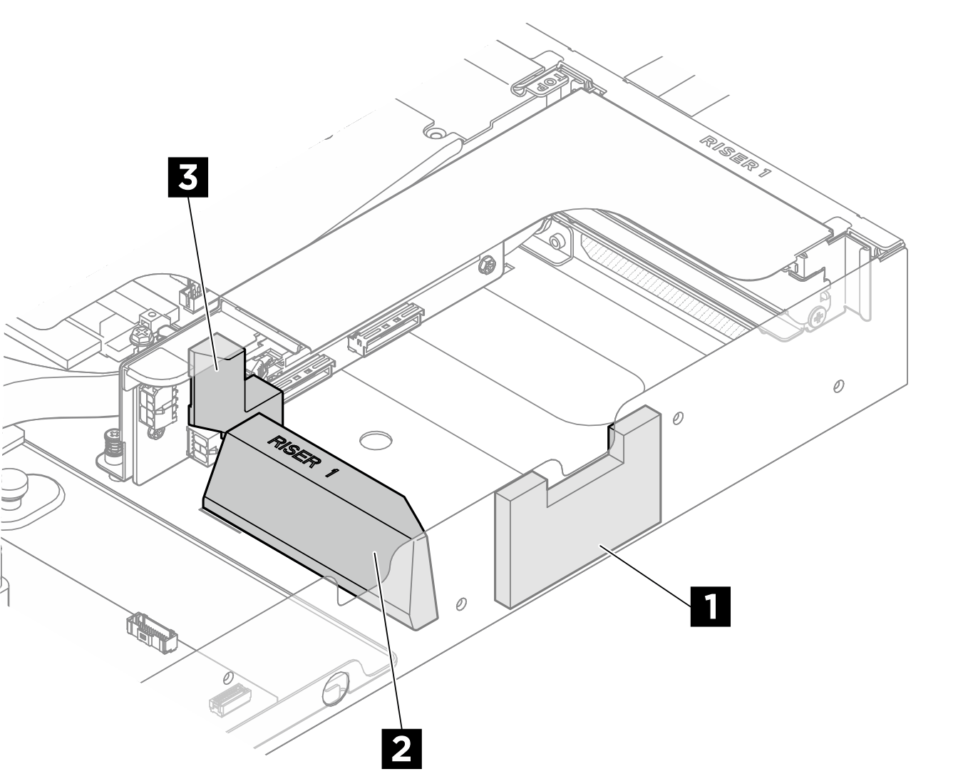
- DPU air baffle location in riser 1 slot.Figure 1. DPU air baffle location in riser 1 slot
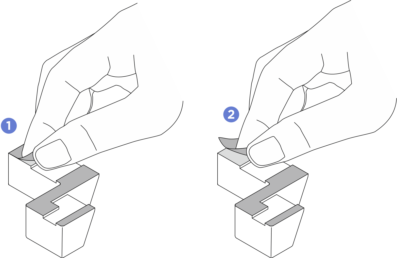
- Install the DPU air baffles in riser 1 slot.NoteRemove the liner from the adhesive on the back of the DPU air baffles before installation.Figure 2. Remove the liner
 Remove the liner from the adhesive on the back of the 1 DPU air baffle, align the air baffle to the marking on the chassis; then, stick the air baffle to the chassis.Figure 3. Installing riser slot 1 DPU air baffle to the chassis
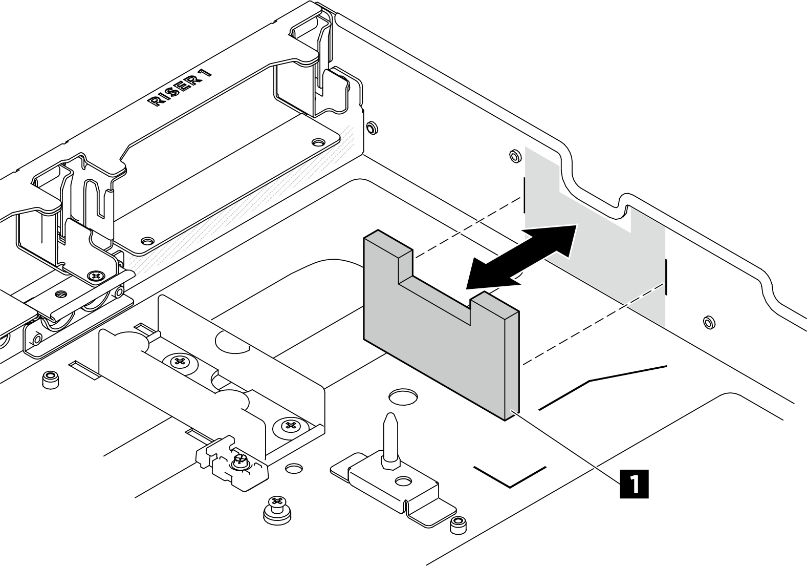
 Remove the liner from the adhesive on the back of the 2 DPU air baffle, align the air baffle to the marking on the chassis; then, stick the air baffle to the chassis.Figure 4. Installing DPU air baffle to the chassis
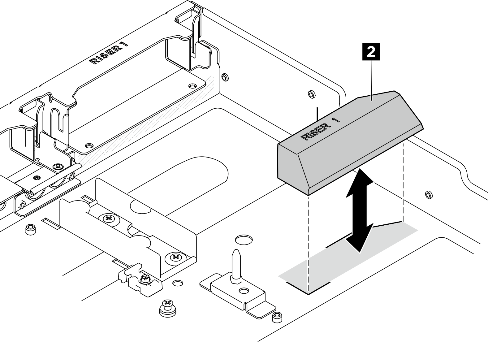
 Remove the liner from the adhesive on the back of the 3 DPU air baffle, align the air baffle to avoid the connectors on the PCIe riser card; then, stick the air baffle to the PCIe riser card as illustrated.Figure 5. Installing DPU air baffle to the PCIe riser card
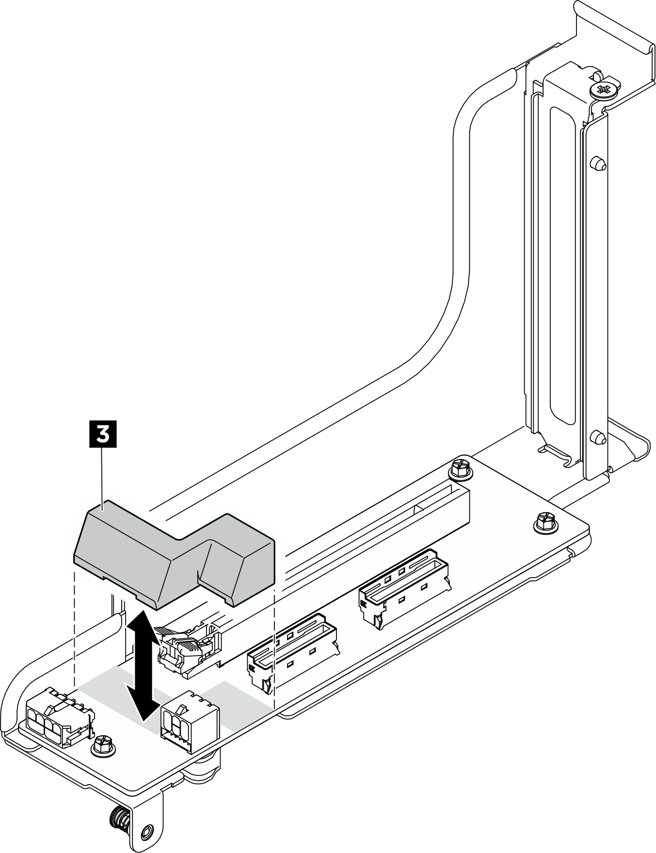
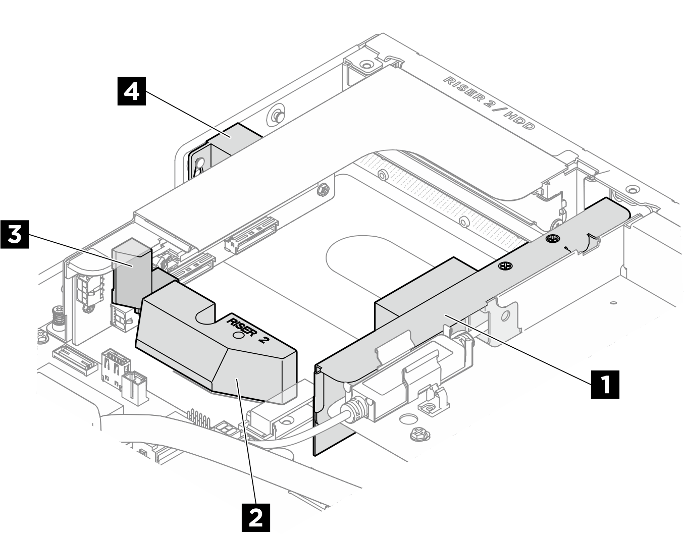
- DPU air baffle location in riser 2 slot.Figure 6. DPU air baffle location in riser 2 slot
- Install the DPU air baffles in riser 2 slot.NoteRemove the liner from the adhesive on the back of the DPU air baffles before installation.Figure 7. Remove the liner
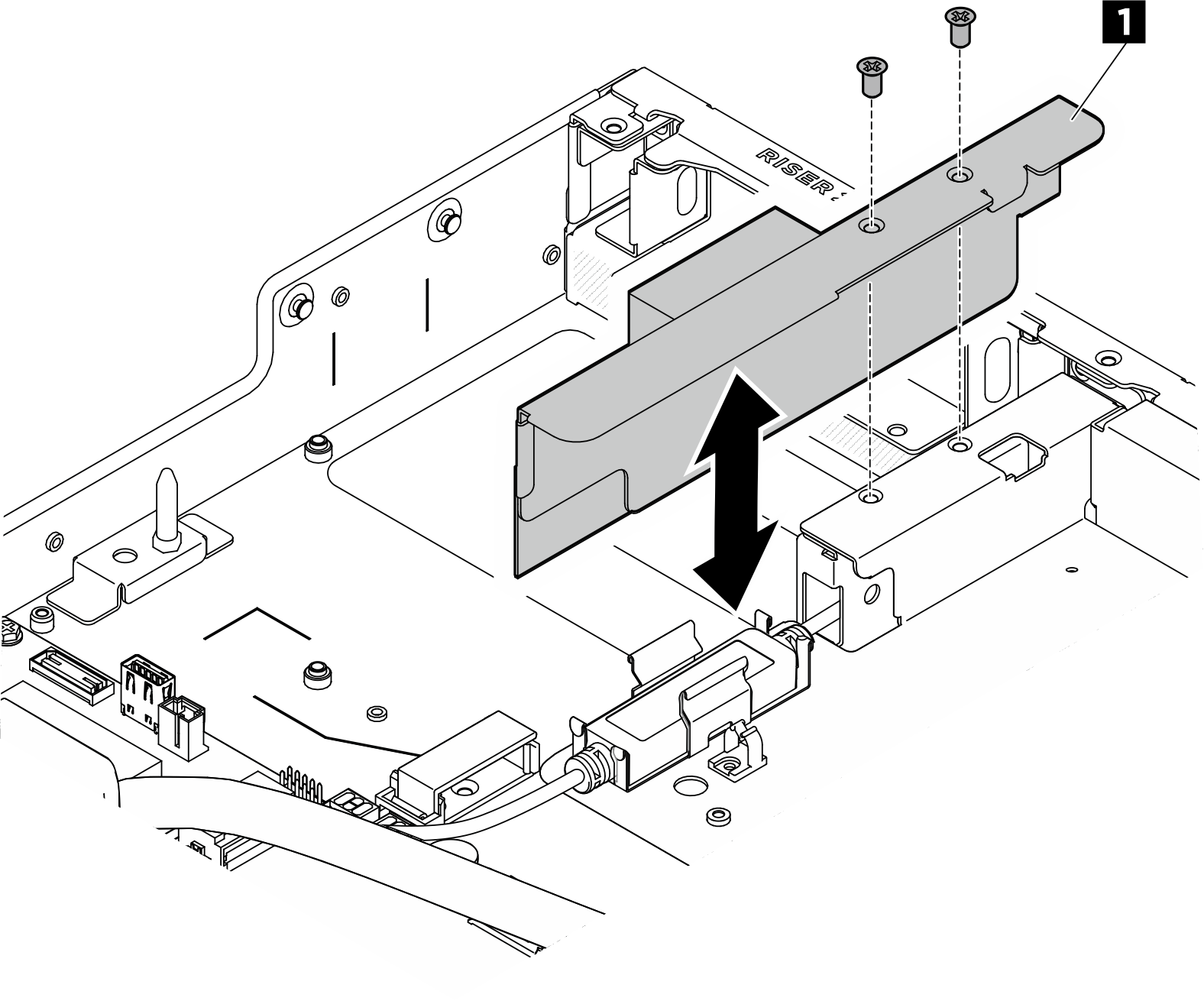
- Align the 1 DPU air baffle and bracket assembly to the leakage sensor module bracket; then, insert the air baffle assembly into the slot. Fasten the two M3 screws (PH1, 2 x M3, 0.5 newton-meters, 4.3 inch-pounds) to secure the air baffle assembly in place.Figure 8. Installing DPU air baffle and bracket assembly
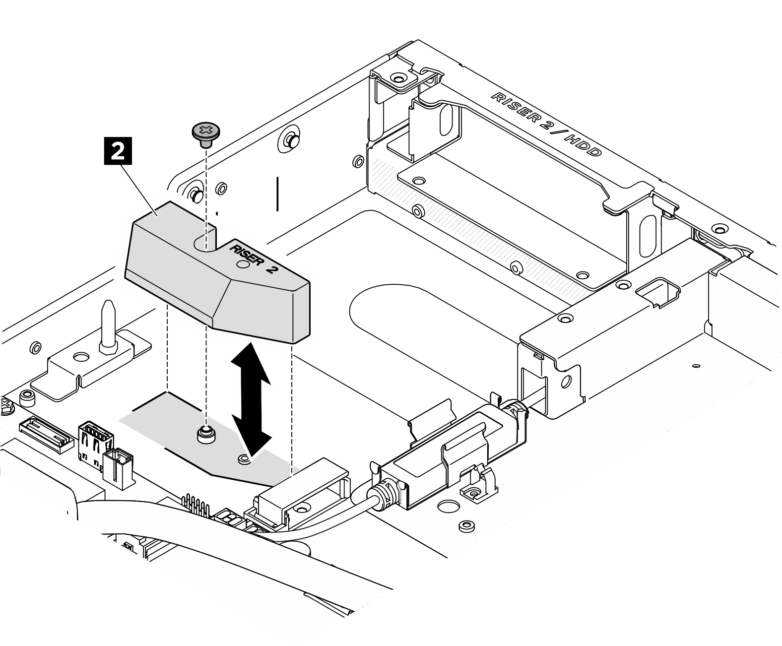
- Remove the liner from the adhesive on the 2 DPU air baffle, align the air baffle to the marking on the chassis; then, stick the air baffle to the chassis. Fasten the M3 screw (PH2, 1 x M3, 0.5 newton-meters, 4.3 inch-pounds) to secure the DPU air baffle.Figure 9. Installing DPU air baffle to the chassis
- Remove the liner from the adhesive on the back of the 3 DPU air baffle, align the air baffle to avoid the connectors on the PCIe riser card; then, stick the air baffle to the PCIe riser card as illustrated.Figure 10. Installing DPU air baffle to the PCIe riser card
 Remove the liner from the adhesive on the back of the 4 DPU air baffle, align the keyhole on the air baffle to the pin on the chassis; then, engage the air baffle with the chassis. Fasten the M3 screw (PH2, 1 x M3, 0.5 newton-meters, 4.3 inch-pounds) to secure the air baffle to the chassis.Figure 11. Installing DPU air baffle to the chassis
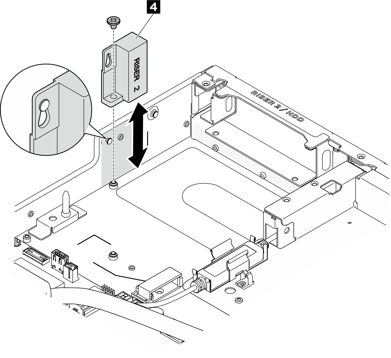
After you finish
- Reconnect all the cables that were disconnected. See Internal cable routing.
- If applicable, reinstall the PCIe riser assembly(ies). See Install a PCIe riser assembly.
- Reinstall the processor air baffle. See Install the processor air baffle.
- Reinstall the rear top cover. See Install the rear top cover.
- Reinstall the front top cover. See Install the front top cover.
- Complete the parts replacement. See Complete the parts replacement.
Give documentation feedback