Install the rear air baffle
Follow the instructions in this section to install the rear air baffle.
About this task
Read Installation Guidelines and Safety inspection checklist to ensure that you work safely.
Power off the server and peripheral devices and disconnect the power cords and all external cables. See Power off the server.
If the server is installed in a rack, slide the server out on its rack slide rails to gain access to the top covers, or remove the server from the rack. See Remove the server from rails.
If you intend to install memory modules in the server, you must first remove the air baffle from the server.
For proper cooling and airflow, reinstall the front and rear air baffles before you turn on the server. Operating the server with the air baffle removed might damage server components.
Procedure
- Align the rear air baffle tabs with the rear air baffle slots on both sides of the chassis; then, lower the rear air baffle into the server.NoteClose the retaining clip on each end of the memory module connector before installing the front air baffle for proper cooling.Figure 1. Installing rear air baffle for 3U standard PHM
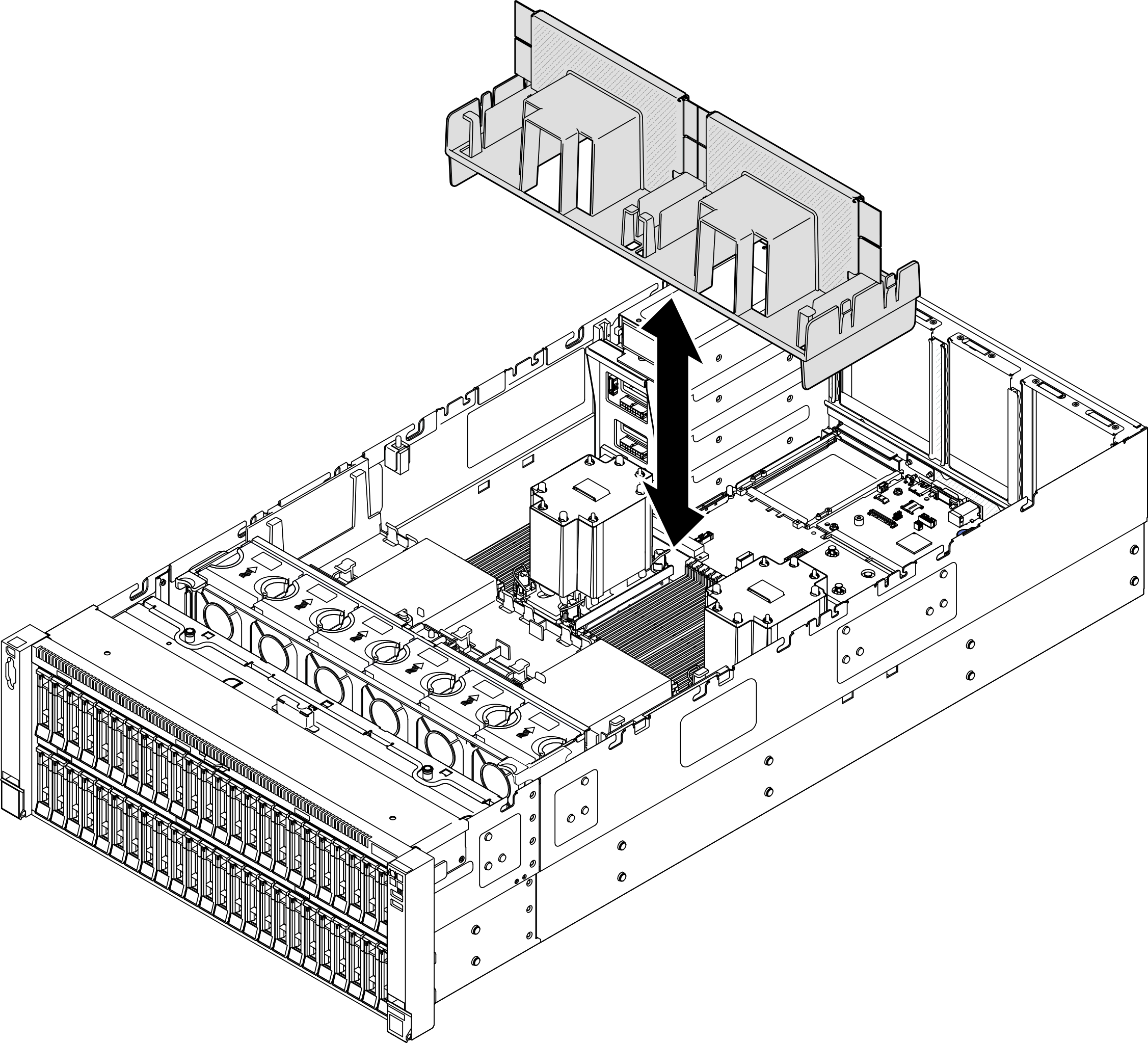 Figure 2. Installing rear air baffle for 2U performance PHM
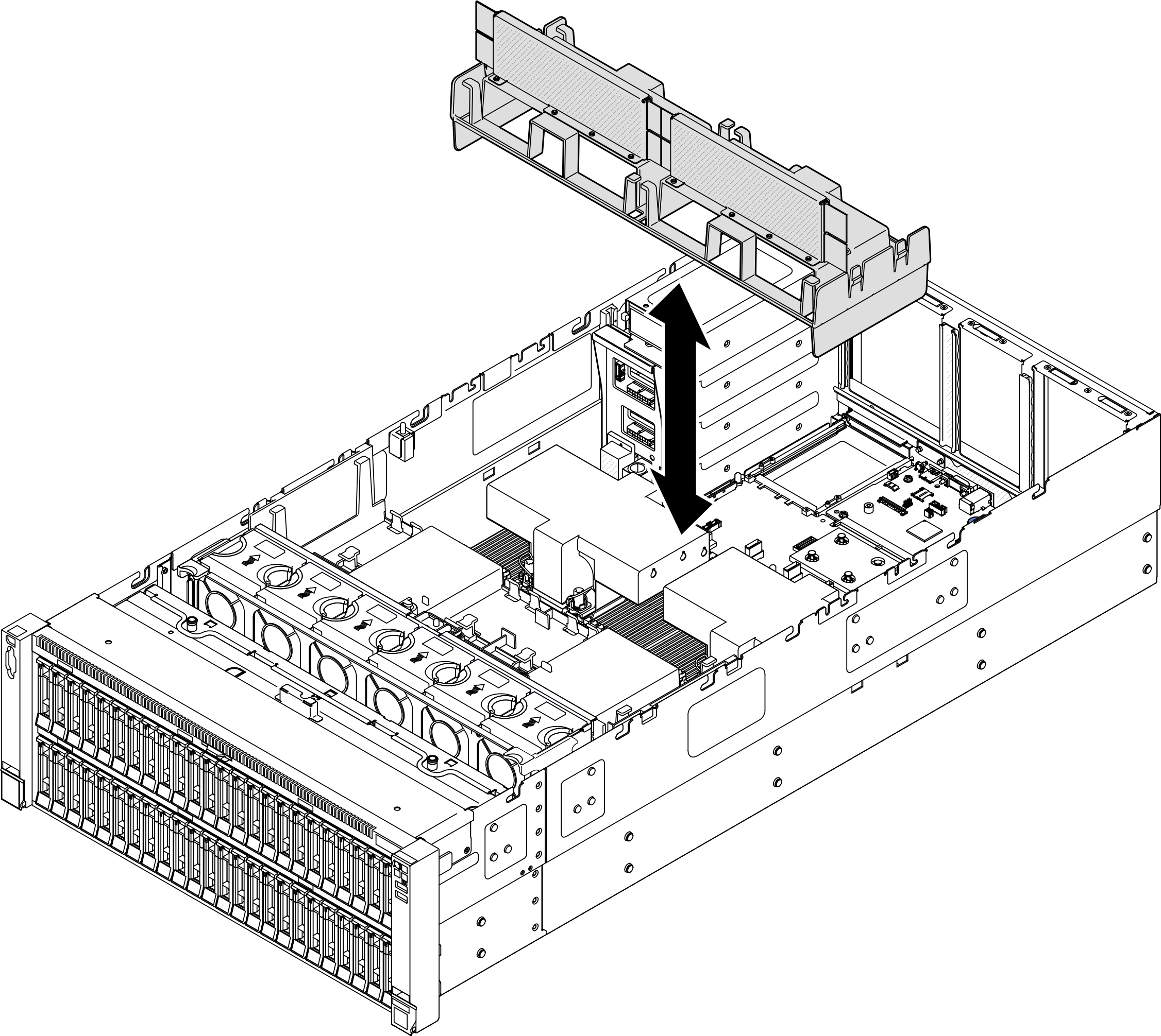
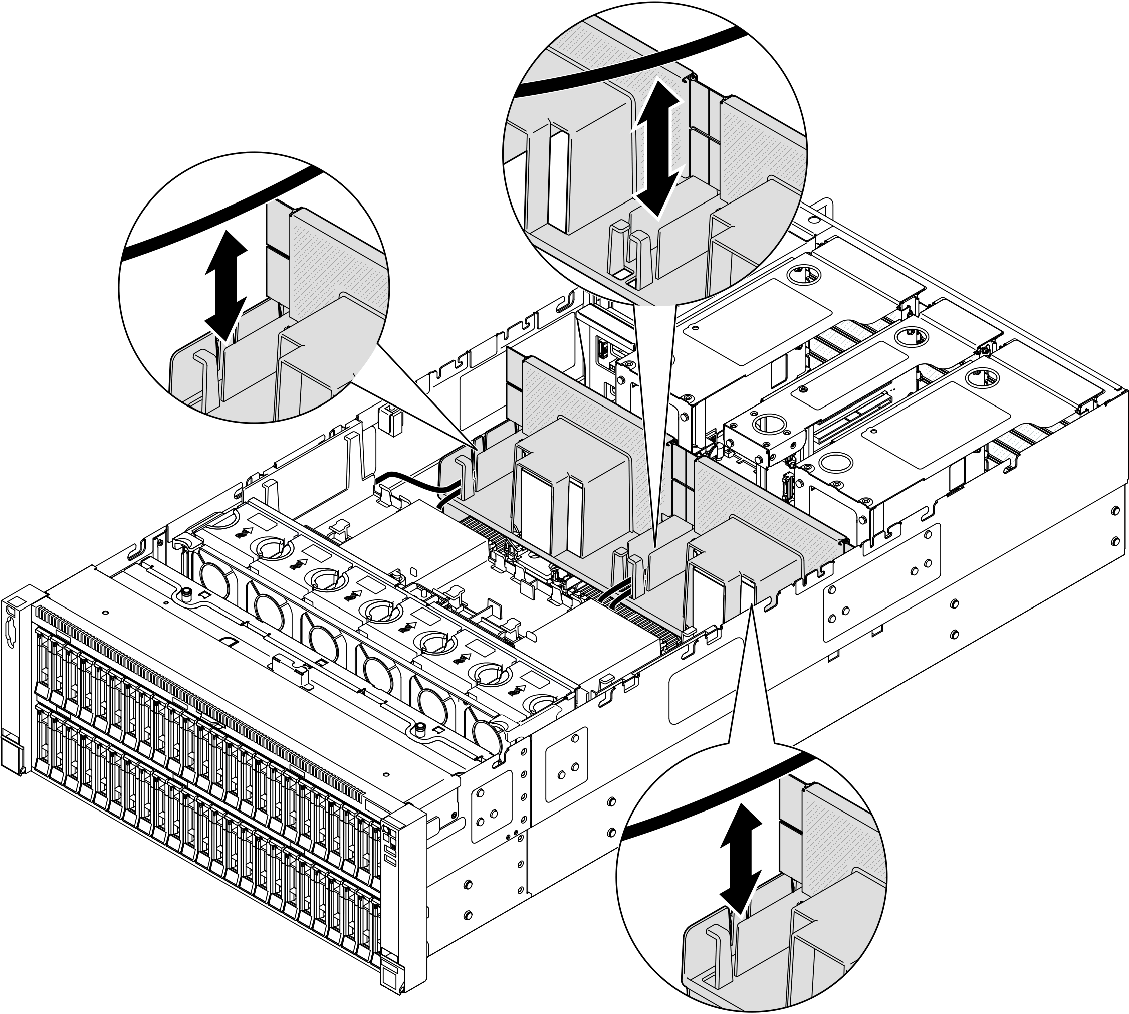
- Route the cables through the rear air baffle.Figure 3. Routing cable through rear air baffle
- If applicable, connect the cables to the M.2 boot adapter.SATA/x4 NVMe M.2 boot adapterFigure 4. Connecting cable to SATA/x4 NVMe M.2 boot adapter
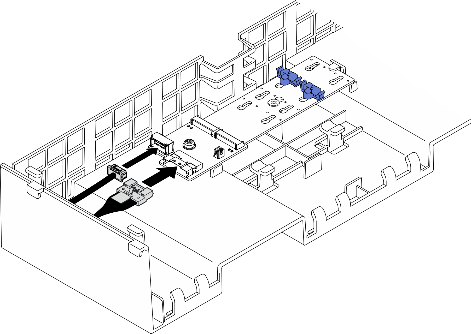 SATA/NVMe or NVMe M.2 boot adapterFigure 5. Connecting cable to SATA/NVMe or NVMe M.2 boot adapter
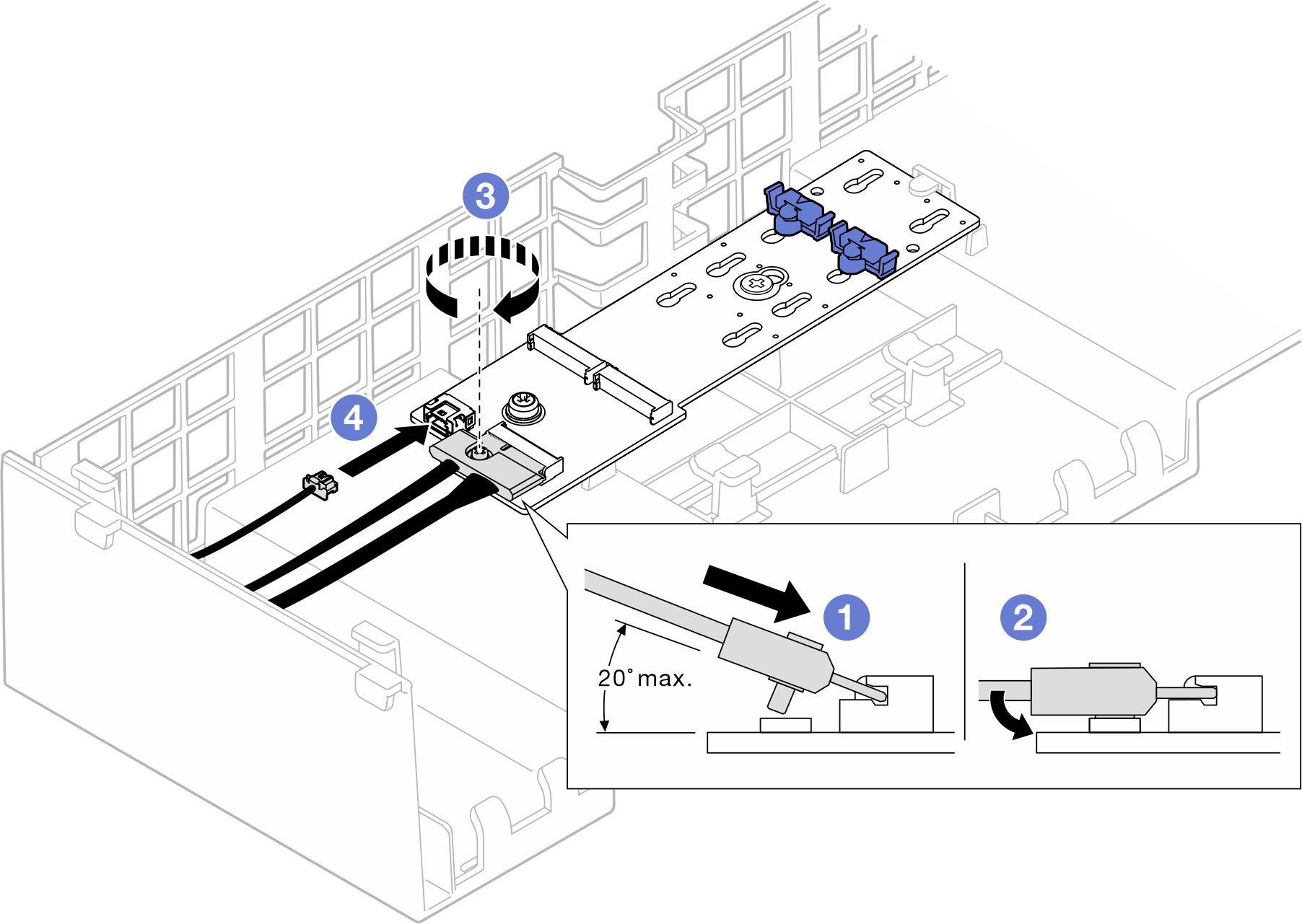
 Tilt the connector at an angle of 20 degrees or lower, and insert it until its bottom surface reaches the ramp.
 Press the connector down flat.
 Tighten the screw on the signal cable.
 Connect the power cable.
RAID SATA/NVMe M.2 boot adapterFigure 6. Connecting cable to RAID SATA/NVMe M.2 boot adapter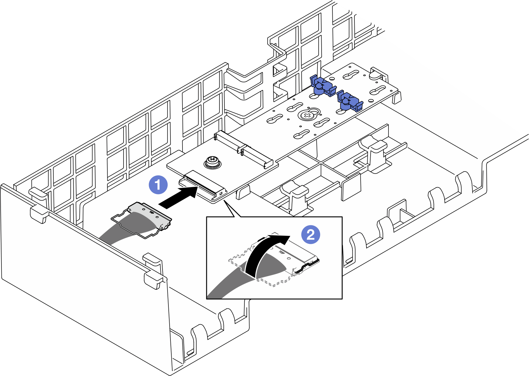
- Connect the cable to the M.2 boot adapter.
- Hook the wire bail on the cable onto the connector.
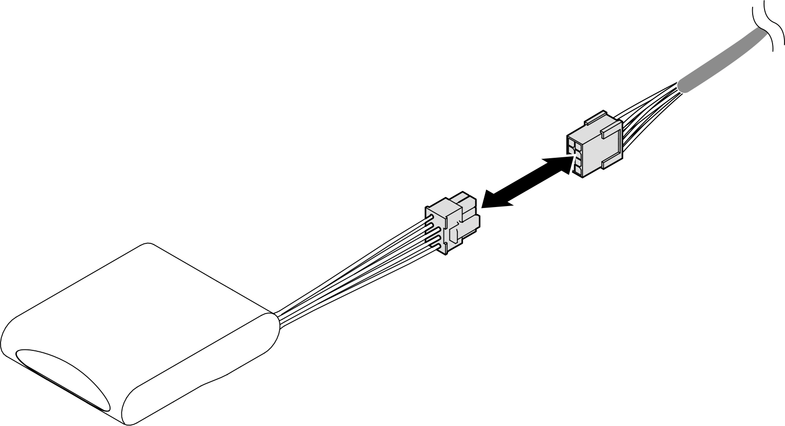
- If applicable, connect the flash power module to an adapter with the extension cable that comes with the flash power module. See Flash power module cable routing for more information on the internal cable routing.Figure 7. Connecting cable to flash power module
After you finish
Reinstall all the PCIe risers. See Install the PCIe riser.
Reinstall the crossbar. See Install the crossbar.
Reinstall the rear top cover. See Install the rear top cover.
Reinstall the front top cover. See Install the front top cover.
Complete the parts replacement. See Complete the parts replacement.
Demo video