Install the server to rails
Follow the instructions in this section to install the server to the rails.
About this task
 |  |
| 18 - 32 kg (39 - 70 lb) | 32 - 55 kg (70 - 121 lb) |
R006  CAUTION Do not place any object on top of a rack-mounted device unless that rack-mounted device is intended for use as a shelf. | S037  CAUTION The weight of this part or unit is more than 55 kg (121.2 lb). It takes specially trained persons, a lifting device, or both to safely lift this part or unit. |
Read Installation Guidelines and Safety inspection checklist to ensure that you work safely.
Power off the server and peripheral devices, disconnect the power cords from the primary chassis, then disconnect the power cords from the secondary chassis. See Power off the server.
Prevent exposure to static electricity, which might lead to system halt and loss of data, by keeping static-sensitive components in their static-protective packages until installation, and handling these devices with an electrostatic-discharge wrist strap or other grounding system.
- Depending on the configuration, your server might be slightly different from the image.
- The primary chassis is shown below as an example, the secondary chassis is similar.
Procedure
- Lift the server and place it on a table. Two lifting options are available:
For two-person lift, remove the following components beforehand:
- All the power supply units
- All the storage drives
- Top cover
Otherwise, lift the server with three people or a lifting device.
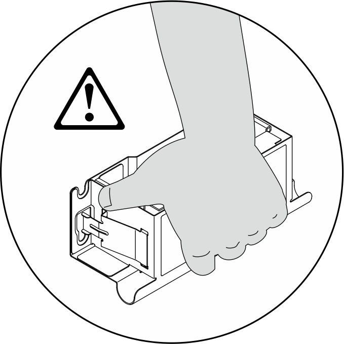
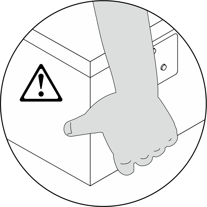
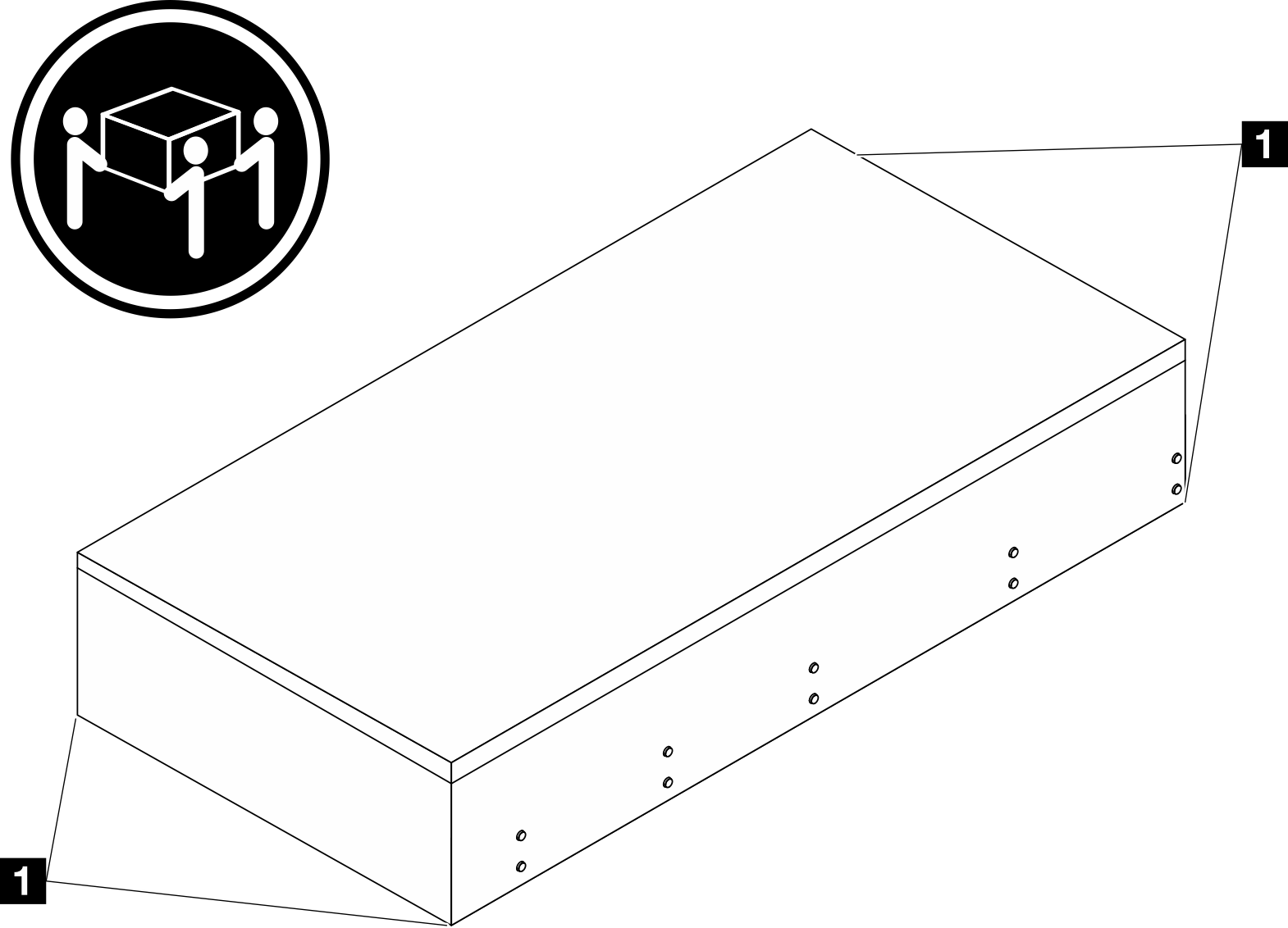 CAUTIONMake sure to lift the server by holding the lift points.
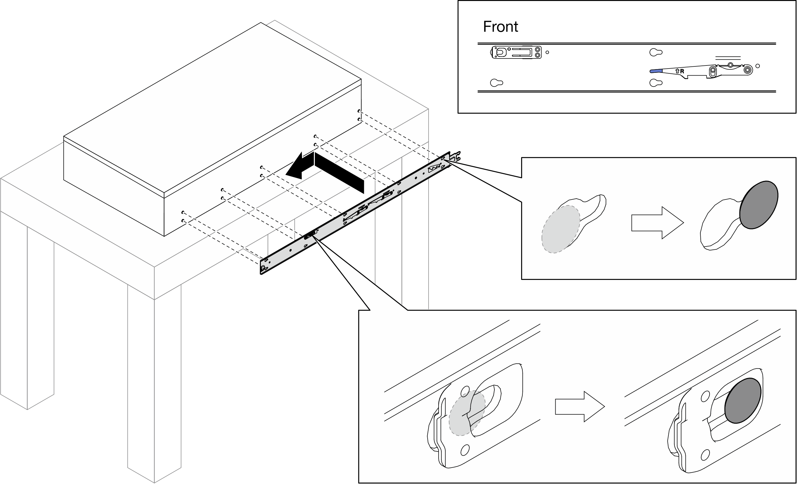
1 Lift point - Remove the inner rails from the intermediate rails.

 Pull the inner rails all the way out until they stop.
 Lift the lock latches, and pull the inner rails to disengage them from the intermediate rails.
AttentionThere are two pairs of lock latches on the rails. Lift the second pair of latches to proceed to slide the inner rails out. Remove the inner rails.
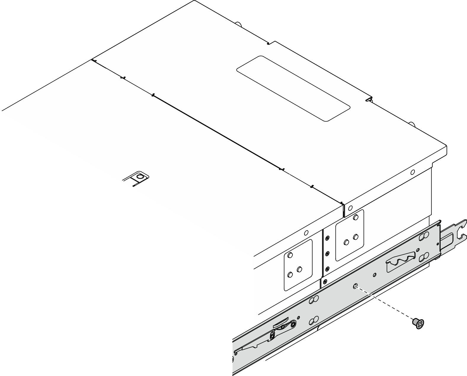
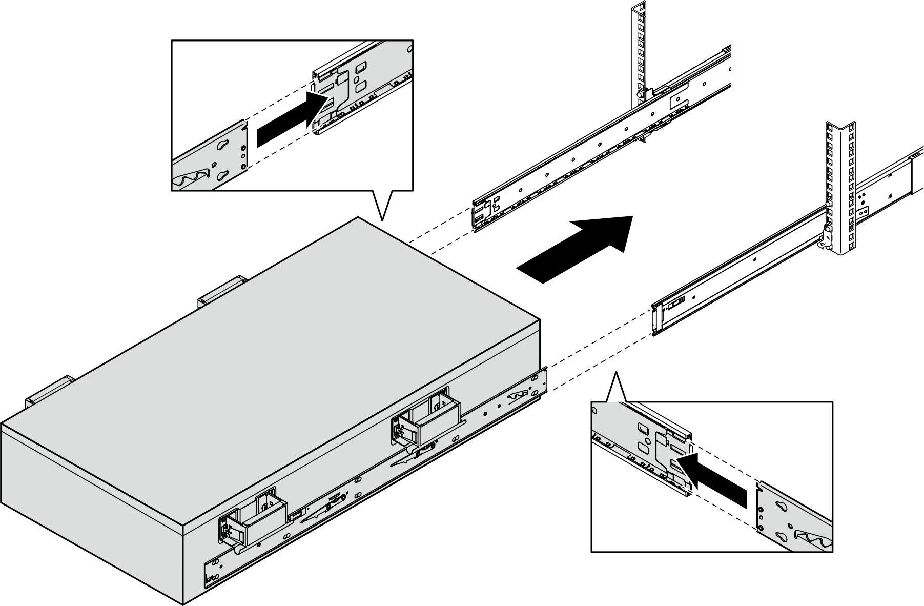
- Align the slots on the inner rail with the corresponding T-pins on the side of the server; then, slide the inner rail forwards until the T-pins lock into place with the inner rail.
- Insert and tighten an M4 screw to secure the inner rail as shown.
- Attach the lift handle.
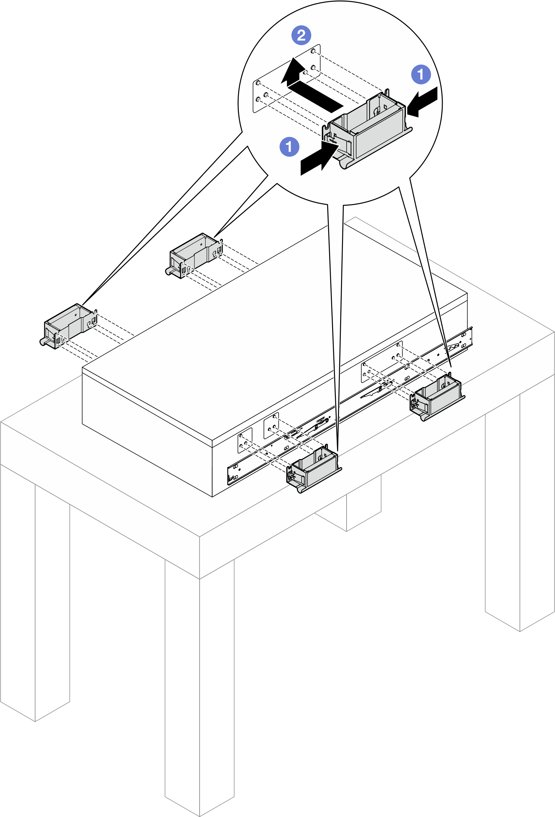
- Pinch both flaps on the side of the handles.
- Align the handles with the 6 posts on the sides of the server; then slide the handles up to secure them to the chassis.
NoteMake sure all 6 posts are secured.
There are 4 lift handles in total. Make sure to install them all properly before lifting the server.
- Install the server to the rack.
 AttentionWhen moving the server, hold the server by its lift points or the lift handles at all time.
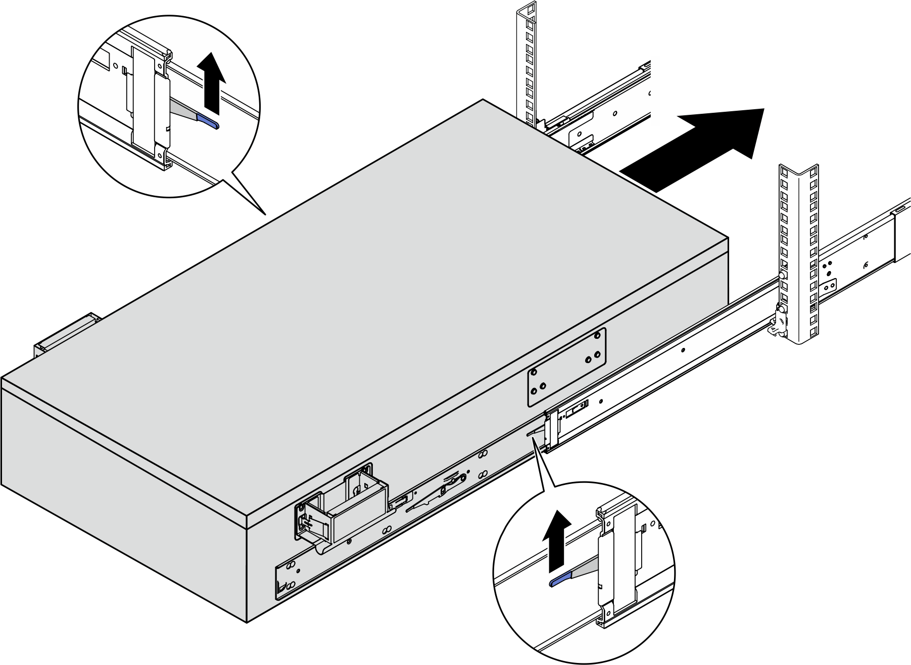
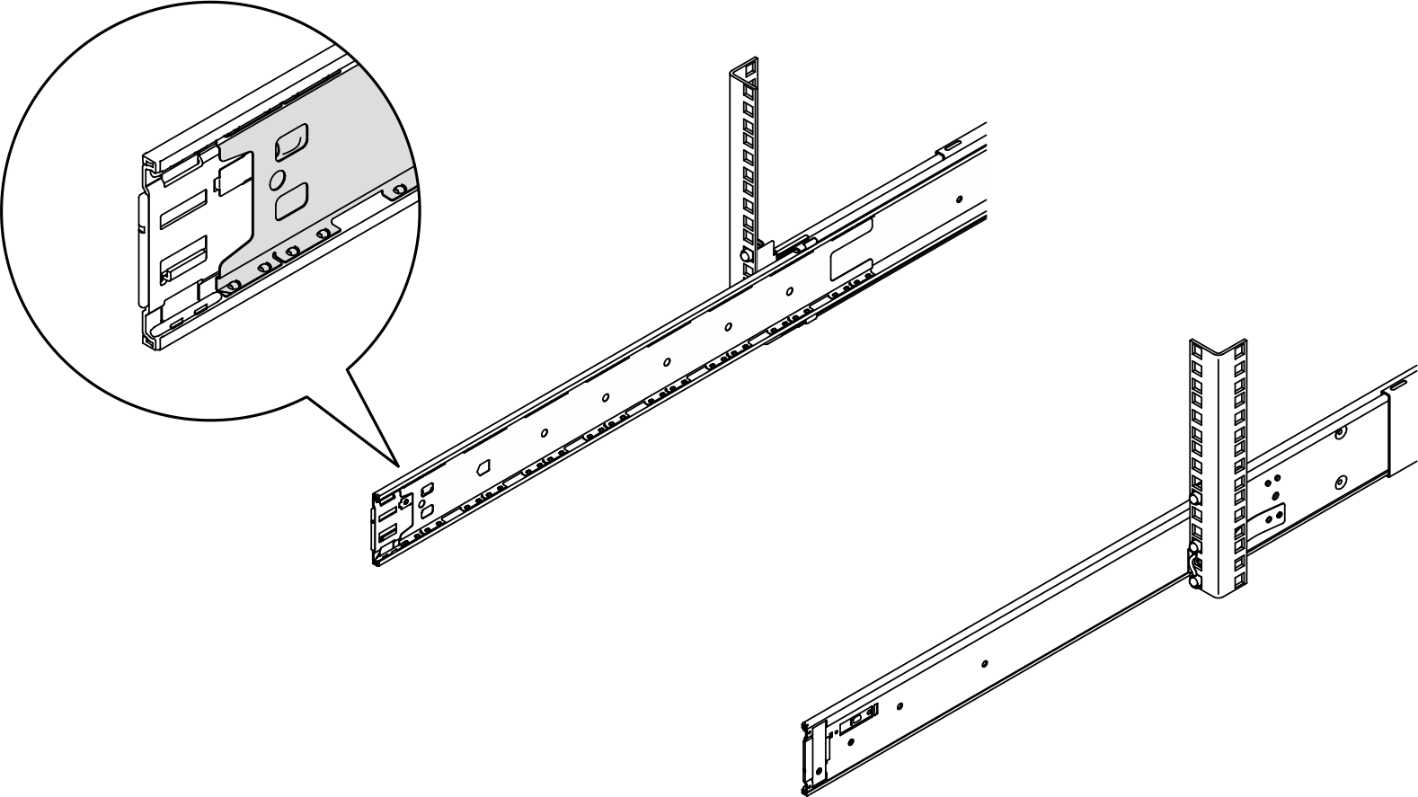 AttentionBefore inner rail is inserted into intermediate rail, ensure that the ball retainer is at the foremost of the intermediate rail.
- Align both rear ends of the inner rails with the openings in the intermediate rails, and make sure the two pairs of rails mate correctly. Then, carefully slide the server into the rack until the rails snap into place.
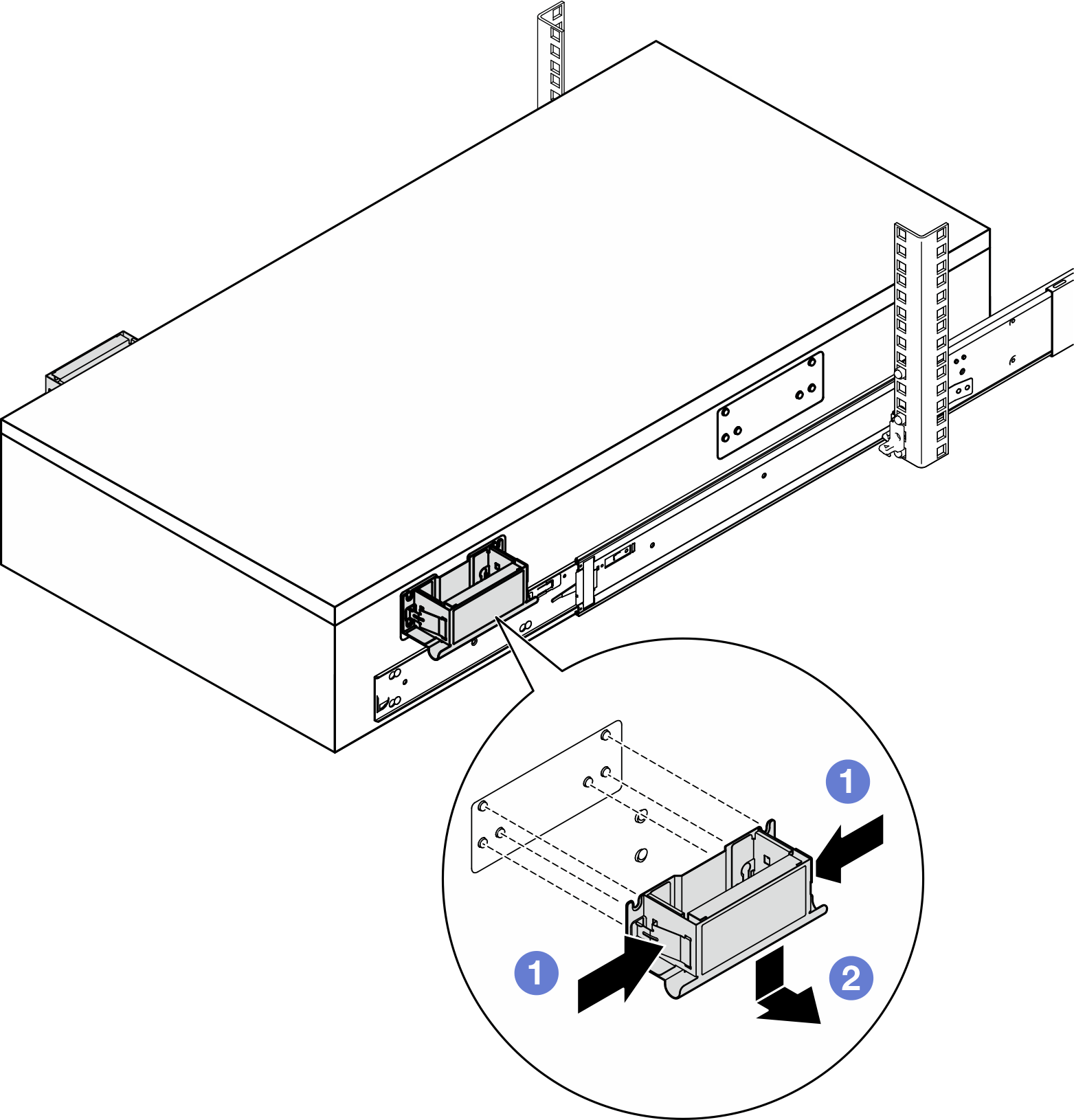
- Remove the rear lift handles.

- Pinch both flaps on the side of the handles.
- Align the handles with the 6 posts on the sides of the server; then, slide the handles down to remove them.
NoteMake sure to remove both rear lift handles before proceeding sliding in. - Lift the first pair of lock latches to proceed to slide the server in until the rails snap into place.
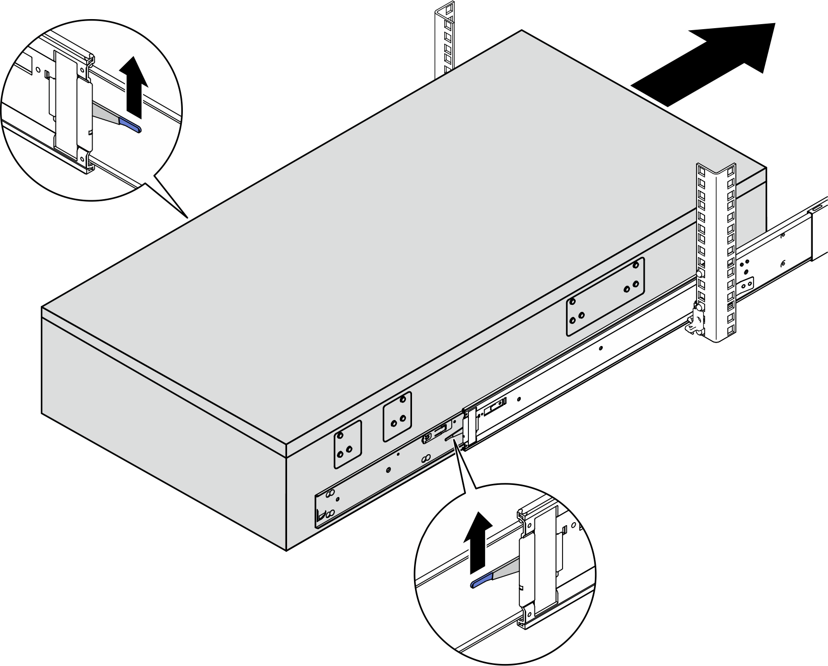
- Remove the front lift handles.
- Pinch both flaps on the side of the handles.
- Align the handles with the 6 posts on the sides of the server; then, slide the handles down to remove them.
NoteMake sure to remove both front lift handles before proceeding to slide the server in.CAUTIONDo not lift the second lock latches until all handles are properly removed. - Lift the second pair of lock latches to proceed to slide the server in.
 AttentionSlide the server all the way out and all the way back in to make sure the rails are working smoothly.
- Align both rear ends of the inner rails with the openings in the intermediate rails, and make sure the two pairs of rails mate correctly. Then, carefully slide the server into the rack until the rails snap into place.
- Connect the external UPI cables to the primary chassis. Make sure the cables match the number and pattern shown on the UPI label.Figure 1. Connecting external UPI cables
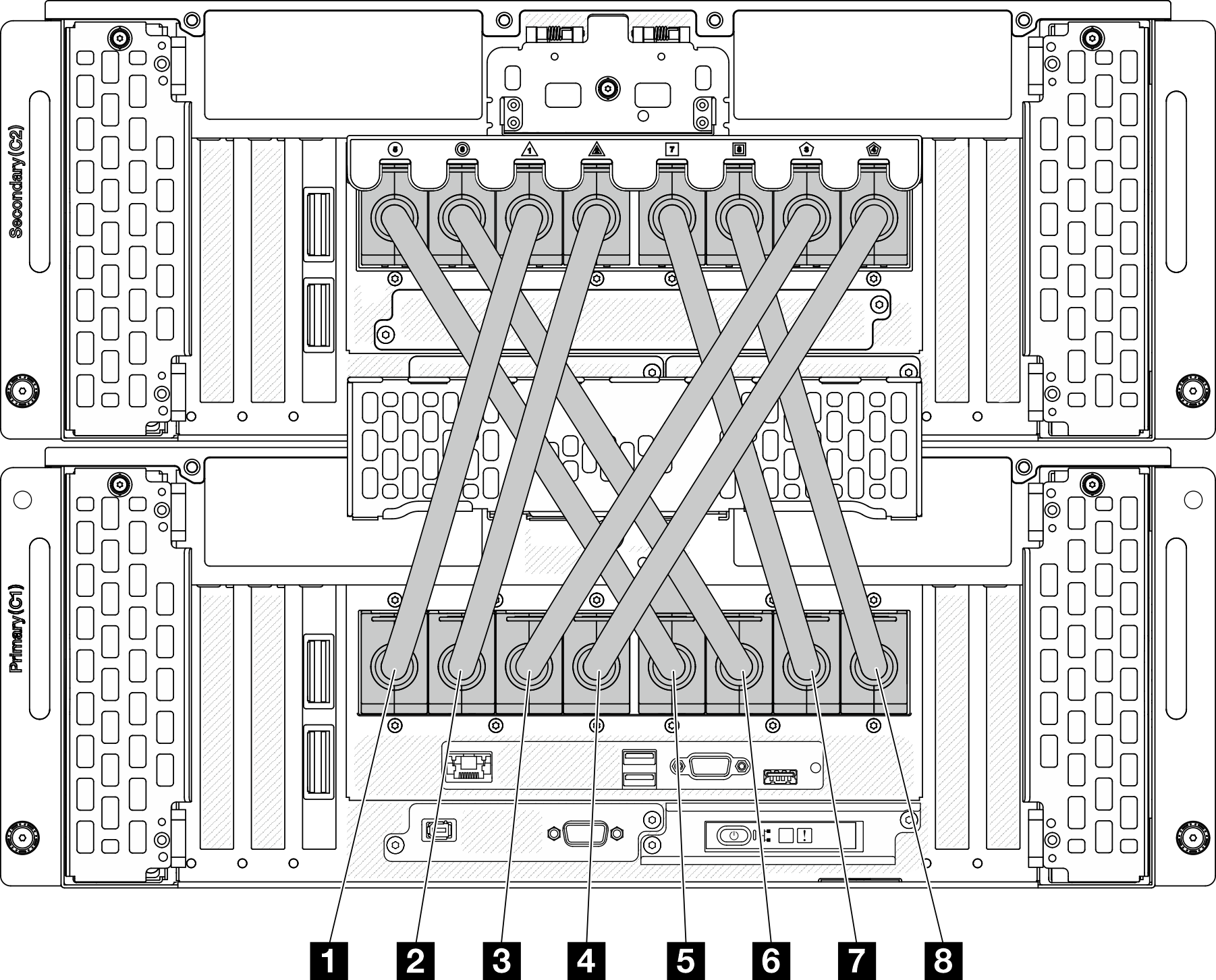
1 External UPI cable 1 5 External UPI cable 5 2 External UPI cable 2 6 External UPI cable 6 3 External UPI cable 3 7 External UPI cable 7 4 External UPI cable 4 8 External UPI cable 8 - Close the UPI cover on the primary chassis.Figure 2. Closing UPI cover
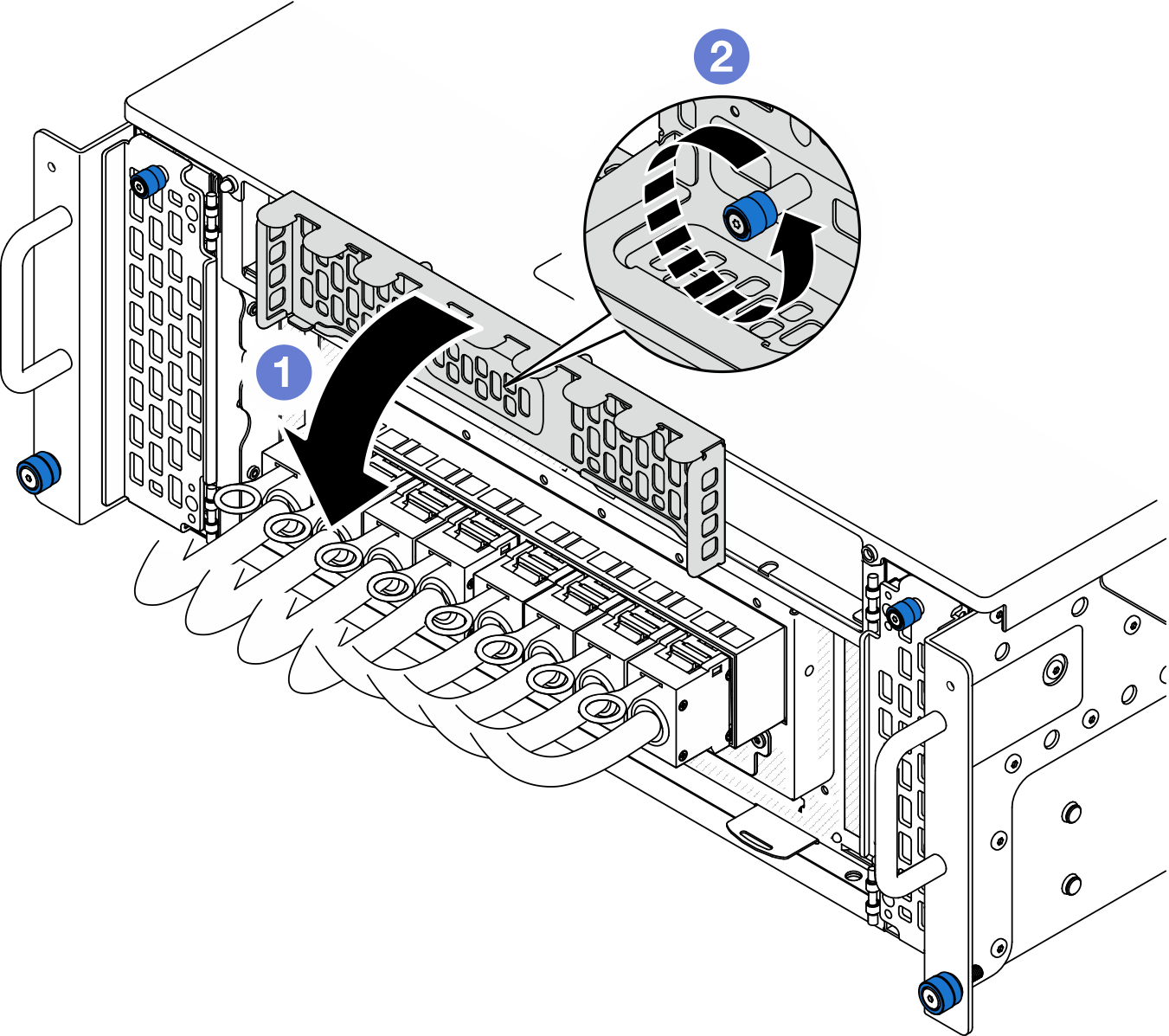
- Close the UPI cover.
- Tighten the thumbscrew to secure the UPI cover. Use a screwdriver if needed.
- Connect the sideband cables to the primary and secondary chassis.Figure 3. Connecting sideband cables
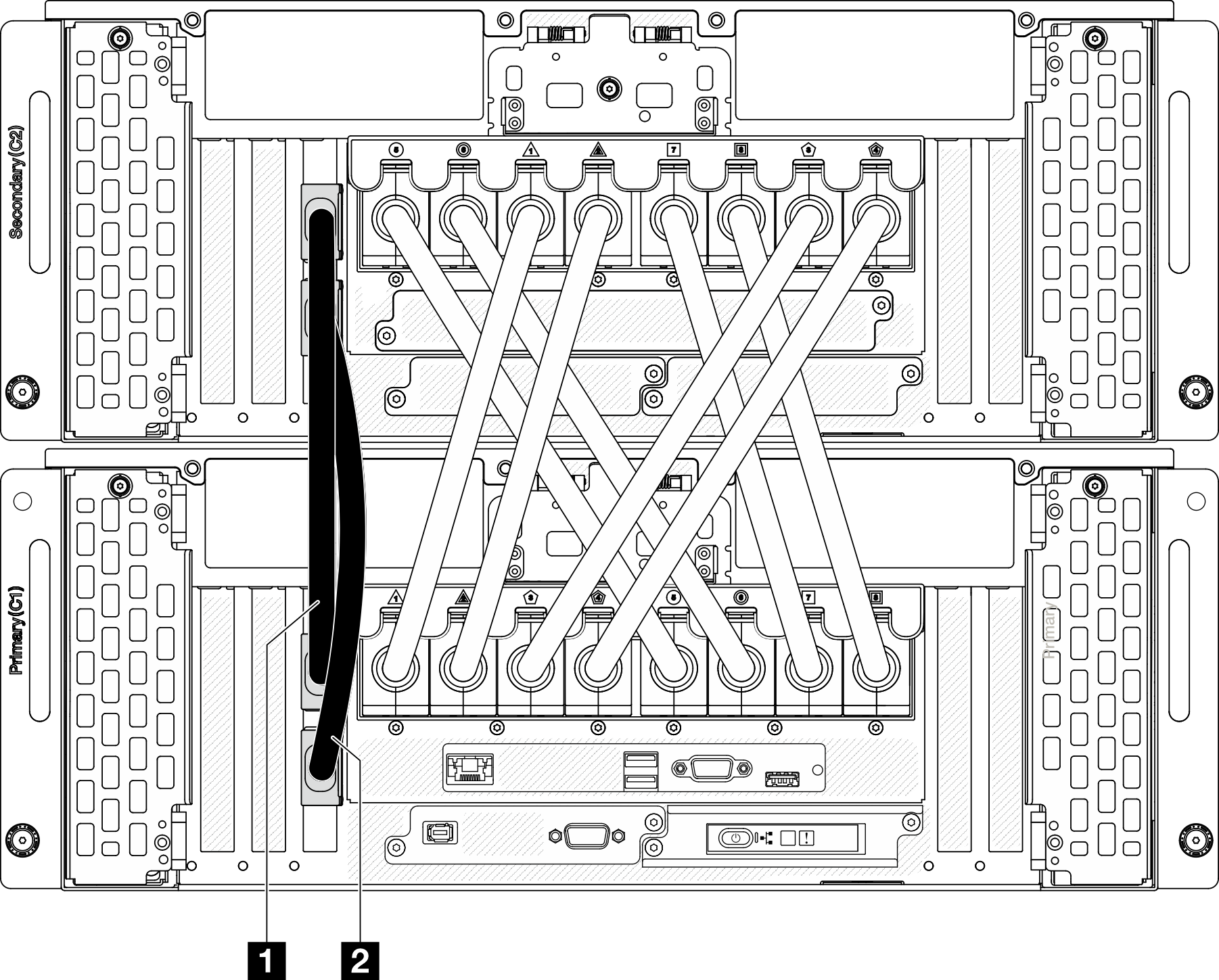
1 Sideband cable 1 1 Sideband cable 2 - (Optional) Secure the server to the rack.
Rear 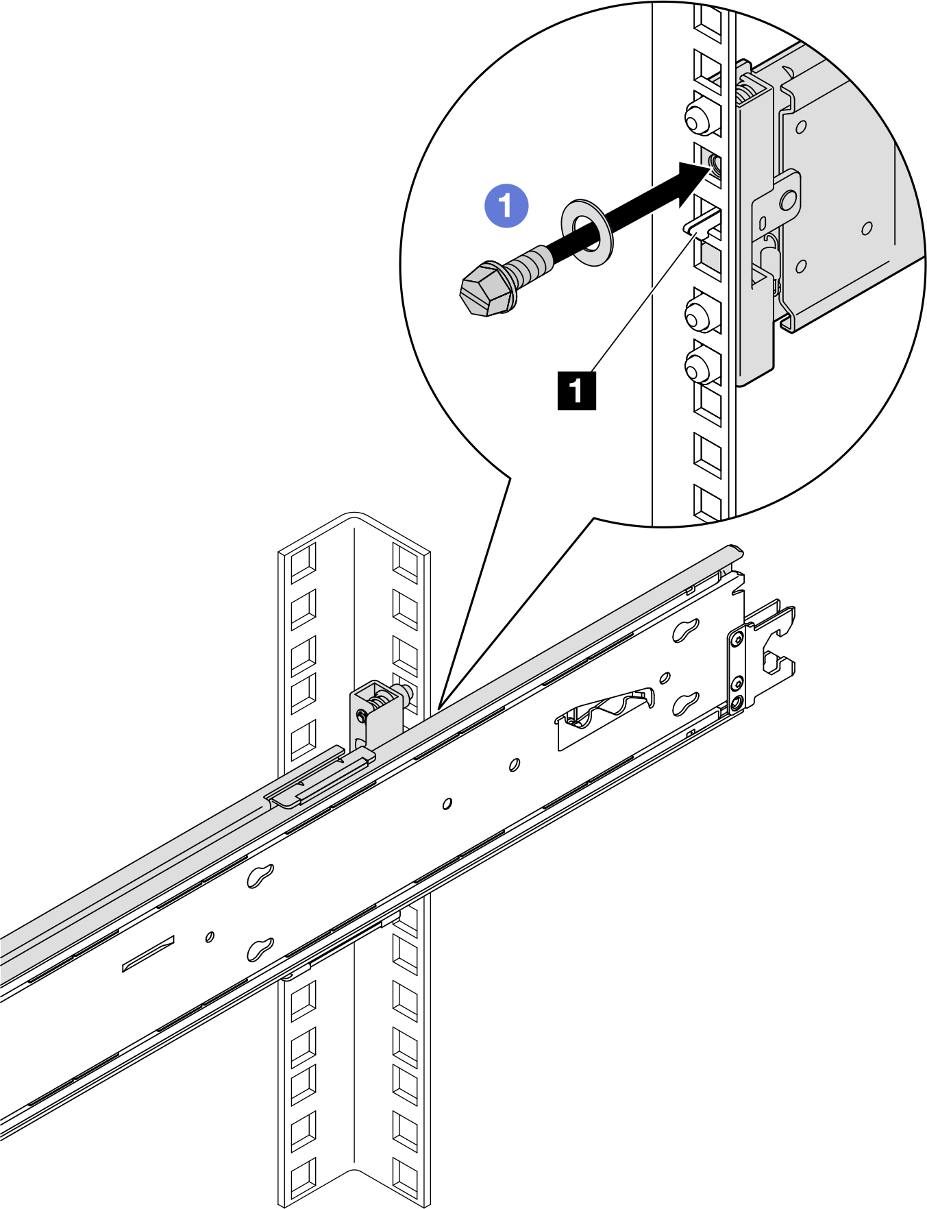
Front 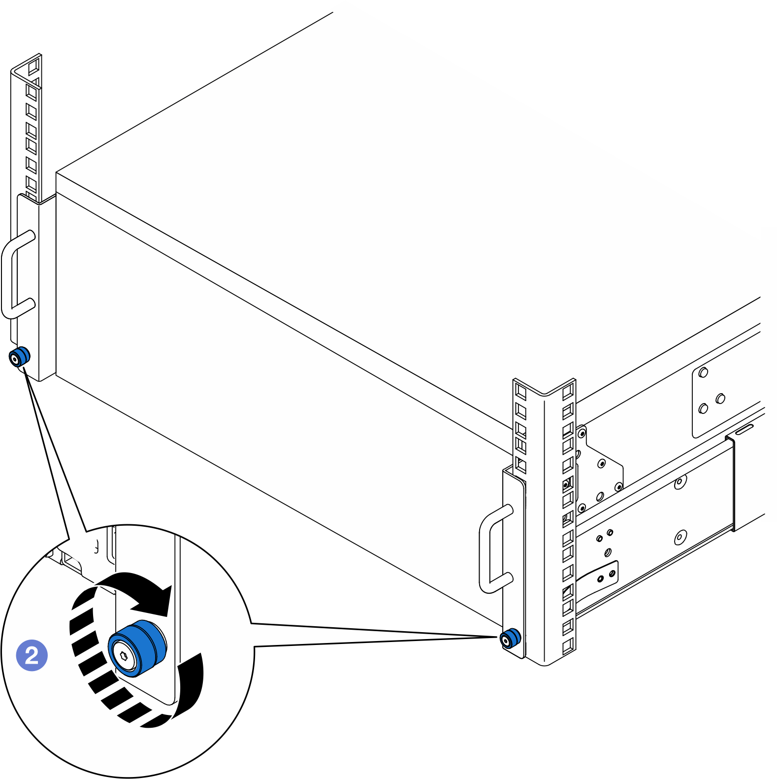
1 Hook latch NoteUse either flat-head, hex socket, or Phillips driver for the following instruction.- Insert and tighten an M5 screw along with a washer to the hole below each hook latch.
- Tighten the thumbscrews. Use a screwdriver if needed.
After you finish
Complete the parts replacement. See Complete the parts replacement.