Remove a 5.25-inch drive bay adapter assembly
Follow the instructions in this section to remove a 5.25-inch drive bay adapter assembly.
About this task

- Do not remove the covers. Removing the covers of the laser product could result in exposure to hazardous laser radiation. There are no serviceable parts inside the device.
- Use of controls or adjustments or performance of procedures other than those specified herein might result in hazardous radiation exposure.
Read Installation Guidelines and Safety inspection checklist to ensure that you work safely.
Power off the server and disconnect all power cords for this task. See Power off the server.
Prevent exposure to static electricity, which might lead to system halt and loss of data, by keeping static-sensitive components in their static-protective packages until installation, and handling these devices with an electrostatic-discharge wrist strap or other grounding system.
If the server is in a rack, remove it from the rack.
Procedure
- Make preparations for this task.
- Remove the server cover. See Remove the server cover.
- Remove the security door. See Remove the security door.
- Remove the front bezel. See Remove the front bezel.
- Disconnect every cable from the 5.25-inch drive bay adapter assembly.
- Remove the 5.25-inch drive bay adapter assembly.
 Press and hold the release tab.
 At the same time, carefully pull the 5.25-inch drive bay adapter assembly to remove it out of the chassis.Figure 1. Removal of a 5.25-inch drive bay adapter assembly
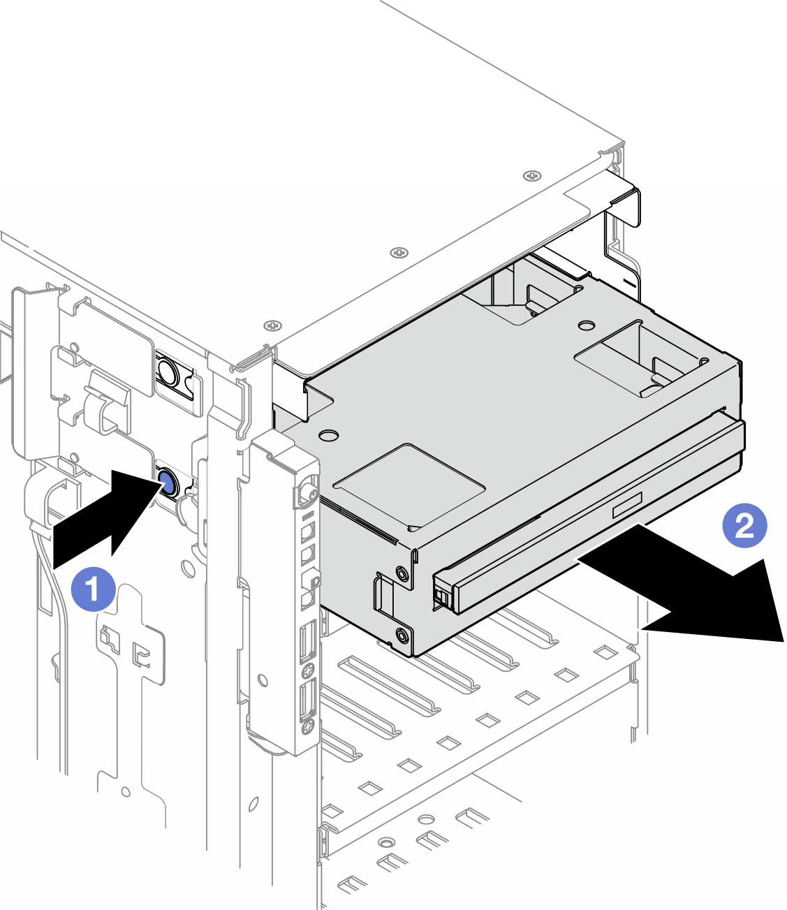
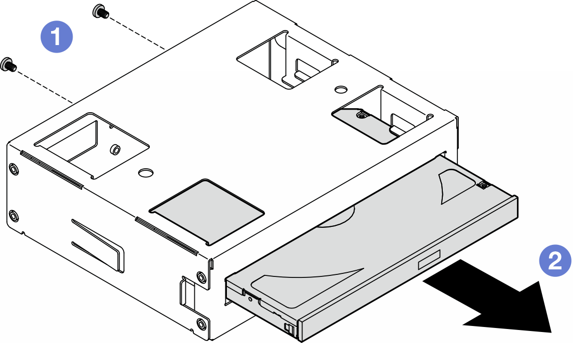
- Remove the slim optical drive out from the adapter.
- Remove the two screws that secure the slim optical drive.
- Slide the slim optical drive out from the adapter.Figure 2. Removal of a slim optical drive from its drive bay adapter
After this task is completed
- Install a replacement unit. See Install a 5.25-inch drive bay adapter assembly. To install a filler, follow the steps below:
Insert the filler to the vacant drive bay.
Figure 3. Installation of a drive bay filler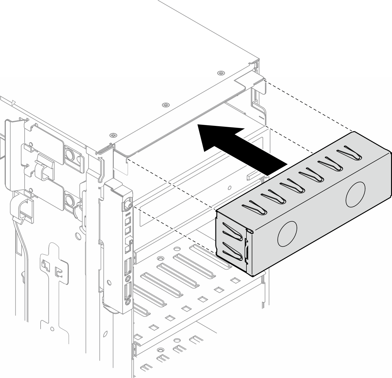
Install the cover of the drive bay filler to the front bezel; then, install the front bezel to the chassis. See Install a front bezel.
Figure 4. Installation of a drive bay filler cover and then a front bezel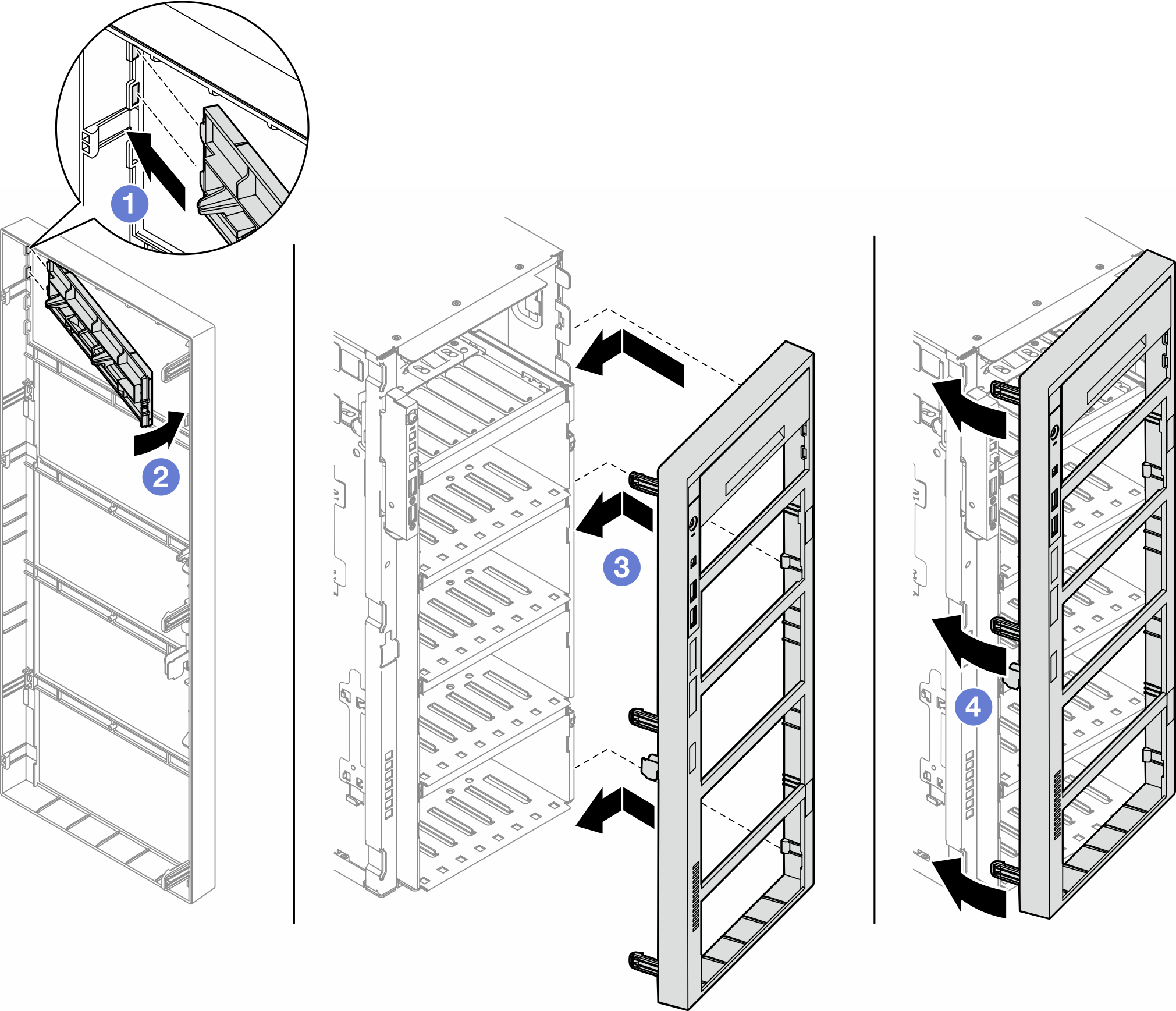
If you are instructed to return the component or optional device, follow all packaging instructions, and use any packaging materials for shipping that are supplied to you.
Demo video