Unbuffered DIMMs (UDIMMs)
The following notes provide information that you must consider when you install UDIMMs:
- The memory channels run at the lowest common frequency of the DIMMs installed.
- The UDIMM options that are available for the server are 1 GB, 2 GB, 4 GB, and 8 GB (when available) DIMMs.
- The server supports up to two single-rank or dual-rank UDIMMs per channel.
The following table lists the supported UDIMM population.
| DIMM connectors per channel | DIMMs installed in each channel | DIMM type | DIMM speed | Ranks per DIMM (any combination) |
|---|---|---|---|---|
| 2 | 1 | Unbuffered DDR3 ECC | 1333, 1600 | Single-rank, dual-rank |
| 2 | 2 | Unbuffered DDR3 ECC | 1333, 1600 | Single-rank, dual-rank |
The following table lists the maximum DIMM population using ranked UDIMMs.
| Number of UDIMMs | DIMM type | Size | Total memory |
|---|---|---|---|
| 4 | Single-rank UDIMMs | 1 GB | 4 GB |
| 4 | Dual-rank UDIMMs | 2 GB | 8 GB |
| 4 | Dual-rank UDIMMs | 4 GB | 16 GB |
| 4 | Dual-rank UDIMMs | 8 GB (when available) | 32 GB |
The following table shows the UDIMM memory population rule to optimize the system performance.
| DIMM connector 1 | DIMM connector 2 | DIMM connector 3 | DIMM connector 4 |
|---|---|---|---|
| Populated | Empty | Empty | Empty |
| Populated | Empty | Populated | Empty |
| Populated | Populated | Populated | Populated |
To install a DIMM on 4U server models with non-hot-swap power supplies, complete the following steps. For the 5U server model with hot-swap power supplies, please see the next sub-section.
- Read the safety information in Safety and Installation guidelines.
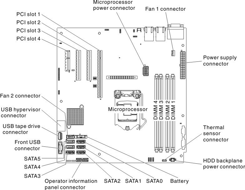
- Locate the DIMM connectors on the system board. Determine the connectors into which you will install the DIMMs. Install the DIMMs in the sequence shown in the following table.
Table 4. DIMM installation sequence. Two column table for documenting the number of DIMMs and installation sequence (connectors).
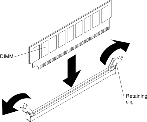
Number of DIMMs Installation sequence (connectors) First pair of DIMMs 1, 3 Second pair of DIMMs 2, 4 - Open the retaining clips and, if necessary, remove any existing DIMM.AttentionTo avoid breaking the retaining clips or damaging the DIMM connectors, open and close the clips gently.Figure 2. DIMM installation
- Touch the static-protective package that contains the DIMM to any unpainted metal surface on the outside of the server. Then, remove the DIMM from the package.
- Turn the DIMM so that the DIMM keys align correctly with the connector.
- Insert the DIMM into the connector by aligning the edges of the DIMM with the slots at the ends of the DIMM connector.
- Firmly press the DIMM straight down into the connector by applying pressure on both ends of the DIMM simultaneously. The retaining clips snap into the locked position when the DIMM is firmly seated in the connector.NoteIf there is a gap between the DIMM and the retaining clips, the DIMM has not been correctly inserted; open the retaining clips, remove the DIMM, and then reinsert it.
- Install the air baffle (see Replacing the air baffle).
- Install the side cover (see Replacing the side cover).
- Stand the server back up in its vertical position.
- Install the bezel (see Replacing the bezel).
- Reconnect the external cables and power cords; then, turn on the attached devices and turn on the server.
To install a DIMM on the 5U server model with hot-swap power supplies, complete the following steps. For 4U server models with non-hot-swap power supplies, please see the above sub-section.
- Read the safety information in Safety and Installation guidelines.
- Locate the DIMM connectors on the system board. Determine the connectors into which you will install the DIMMs. Install the DIMMs in the sequence shown in the following table.
Table 5. DIMM installation sequence. Two column table for documenting the number of DIMMs and installation sequence (connectors).
Number of DIMMs Installation sequence (connectors) First pair of DIMMs 1, 3 Second pair of DIMMs 2, 4 - Open the retaining clips and, if necessary, remove any existing DIMM.AttentionTo avoid breaking the retaining clips or damaging the DIMM connectors, open and close the clips gently.Figure 3. DIMM installation
- Touch the static-protective package that contains the DIMM to any unpainted metal surface on the server. Then, remove the new DIMM from the package.
- Turn the DIMM so that the DIMM keys align correctly with the connector.
- Insert the DIMM into the connector by aligning the edges of the DIMM with the slots at the ends of the DIMM connector. Firmly press the DIMM straight down into the connector by applying pressure on both ends of the DIMM simultaneously. The retaining clips snap into the locked position when the DIMM is firmly seated in the connector. If there is a gap between the DIMM and the retaining clips, the DIMM has not been correctly installed. Open the retaining clips, remove the DIMM, and then reinsert it.
- Stand the server back up in its vertical position.
- Install and lock the side cover (see Replacing the side cover).
- Reconnect the external cables and power cords; then, turn on the attached devices and turn on the server.