Remove the leakage sensor
Use this information to remove the leakage sensor.
About this task
S002
CAUTION
The power-control button on the device and the power switch on the power supply do not turn off the electrical current supplied to the device. The device also might have more than one power cord. To remove all electrical current from the device, ensure that all power cords are disconnected from the power source.
Attention
Read Installation Guidelines and Safety inspection checklist to ensure that you work safely.
Shut down the operating system and turn off any compute nodes in the enclosure. See the documentation that comes with the compute node for detailed instructions.
Disconnect all external cables from the enclosure.
Use extra force to disconnect QSFP cables if they are connected to the solution.
Watch the procedure
- A video of this procedure is available at YouTube.
Procedure
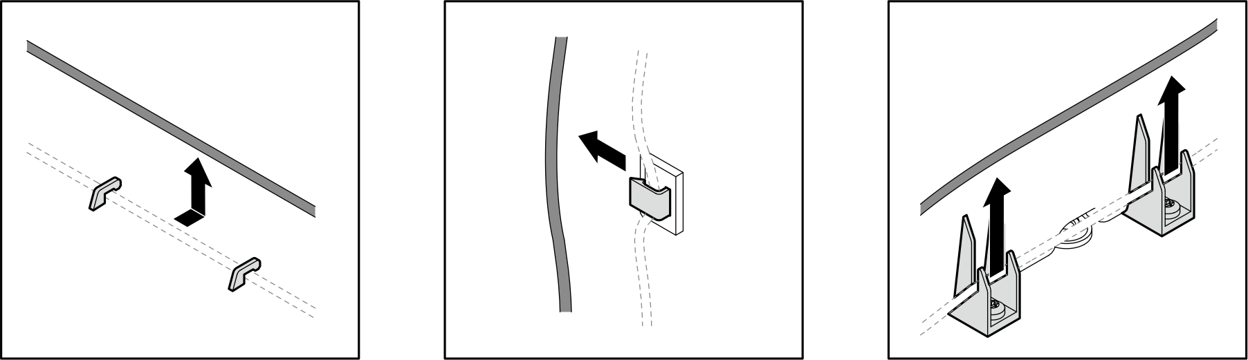
- Remove the leakage sensor cable from the mid-plate.Make sure to remove the cable from all the cable clips. See the illustration below to see cable detached from various types of cable clip.Figure 1. Removing leakage sensor cable from cable clips
 Open the drip tray cover of the top drip tray on the front side of the mid-plate.
 Pull the cable out from the opening on the drip tray cover. Then, pull it out through the guide hole to the rear side of the mid-plate.Figure 2. Removing leakage sensor cable from top drip tray on the front side
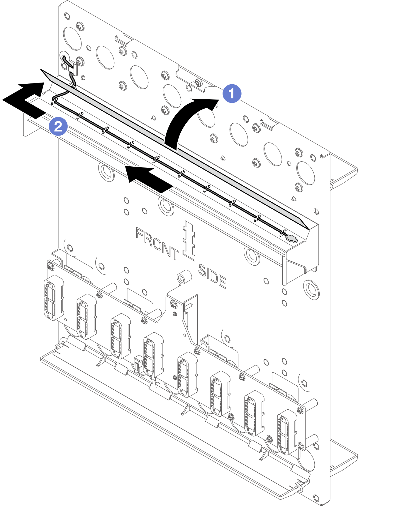
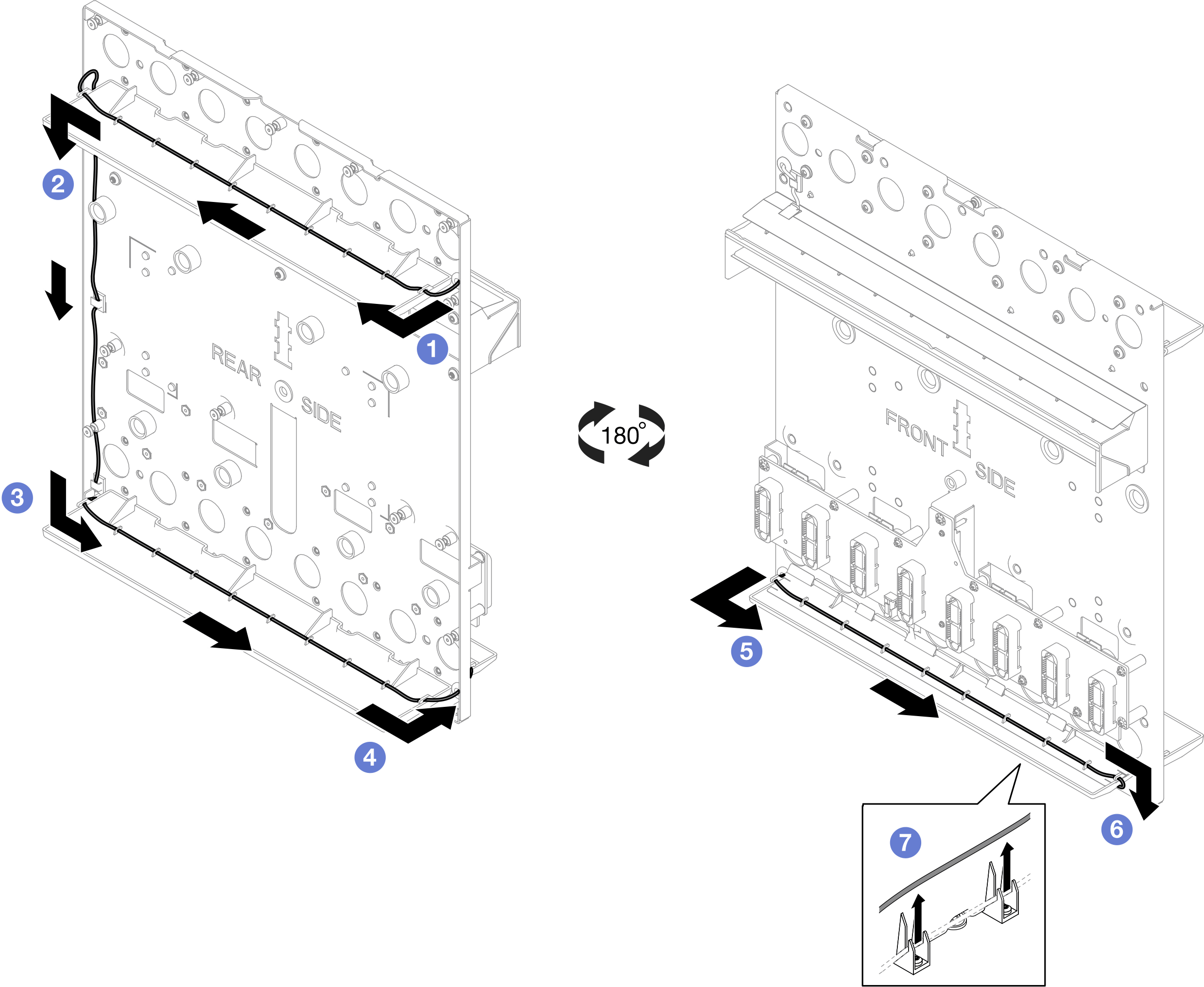
- Remove the leakage sensor cable from rear side to front side. Follow the sequence in the illustration below.
- REAR SIDE: → →
 →
→  (through the guide hole)
 - FRONT SIDE:
 →
→  →
→  (on the bottom-side of the drip tray)
- REAR SIDE:
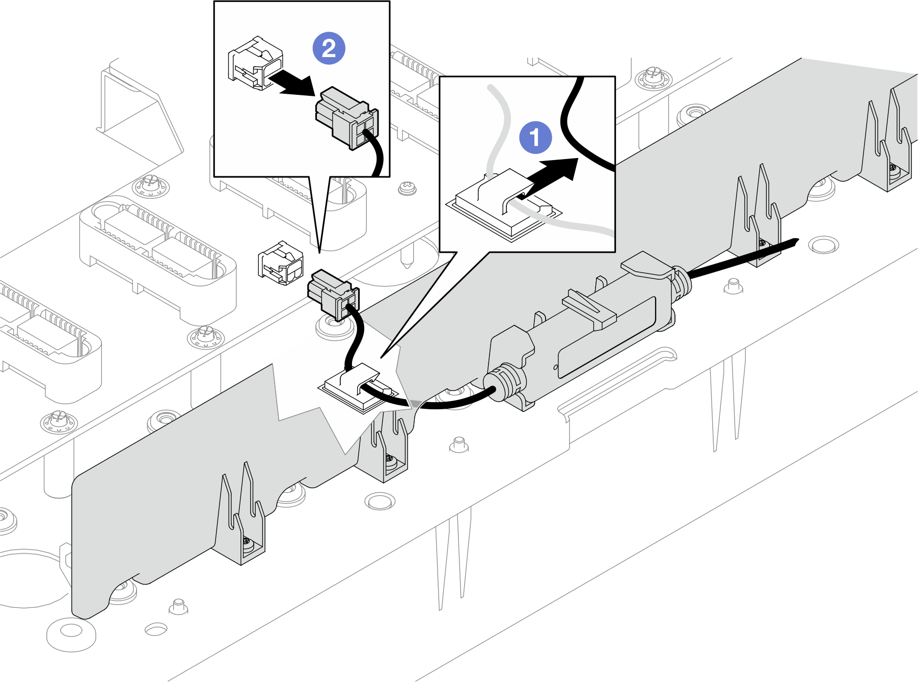
- Remove the leakage sensor module.
- Detach the leakage sensor cable from the cable clip.
- Disconnect the leakage sensor from the interposer card.Figure 3. Disconnecting leakage sensor cable
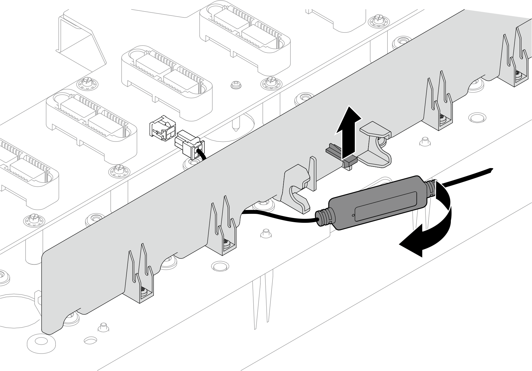
- Pull up the retaining tab and remove the leakage sensor module from the support bracket.
After you finish
If you are instructed to return the component or optional device, follow all packaging instructions, and use any packaging materials for shipping that are supplied to you.
Give documentation feedback