Install the leakage sensor
Use this information to install the leakage sensor.
About this task
Read Installation Guidelines and Safety inspection checklist to ensure that you work safely.
Go to Drivers and Software download website to see the latest firmware and driver updates for your server.
Go to Update the firmware for more information on firmware updating tools.
- A video of this procedure is available at YouTube.
Procedure
- Secure the leakage sensor module to the mid-plate.
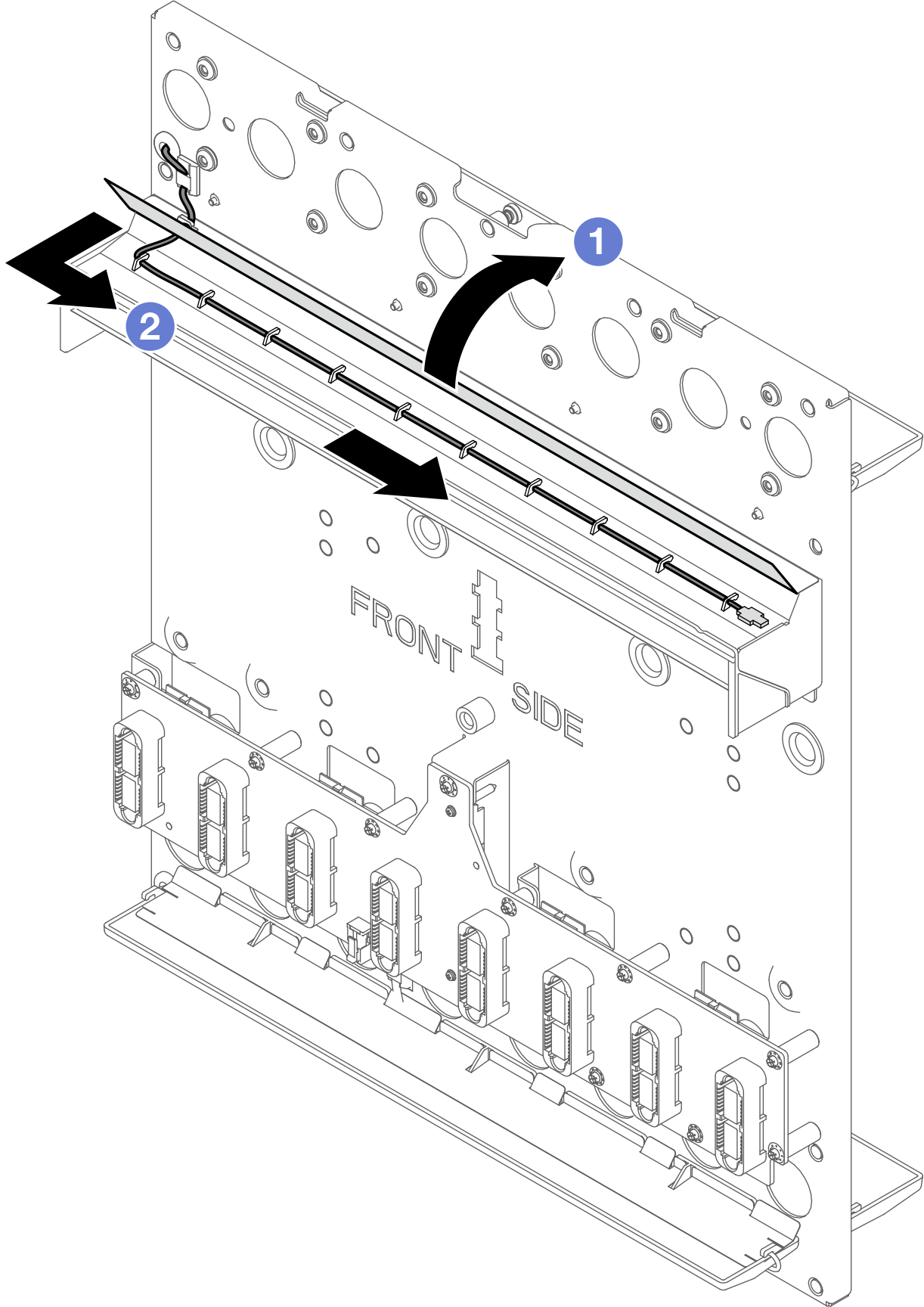
 From the underneath of the bottom drip tray on the front side, insert the cable through the guide hole on the bottom drip tray. Then, connect the cable to the interposer board.
 Secure the leakage sensor cable to the cable clip.Figure 1. Connecting leakage sensor cable to the interposer card
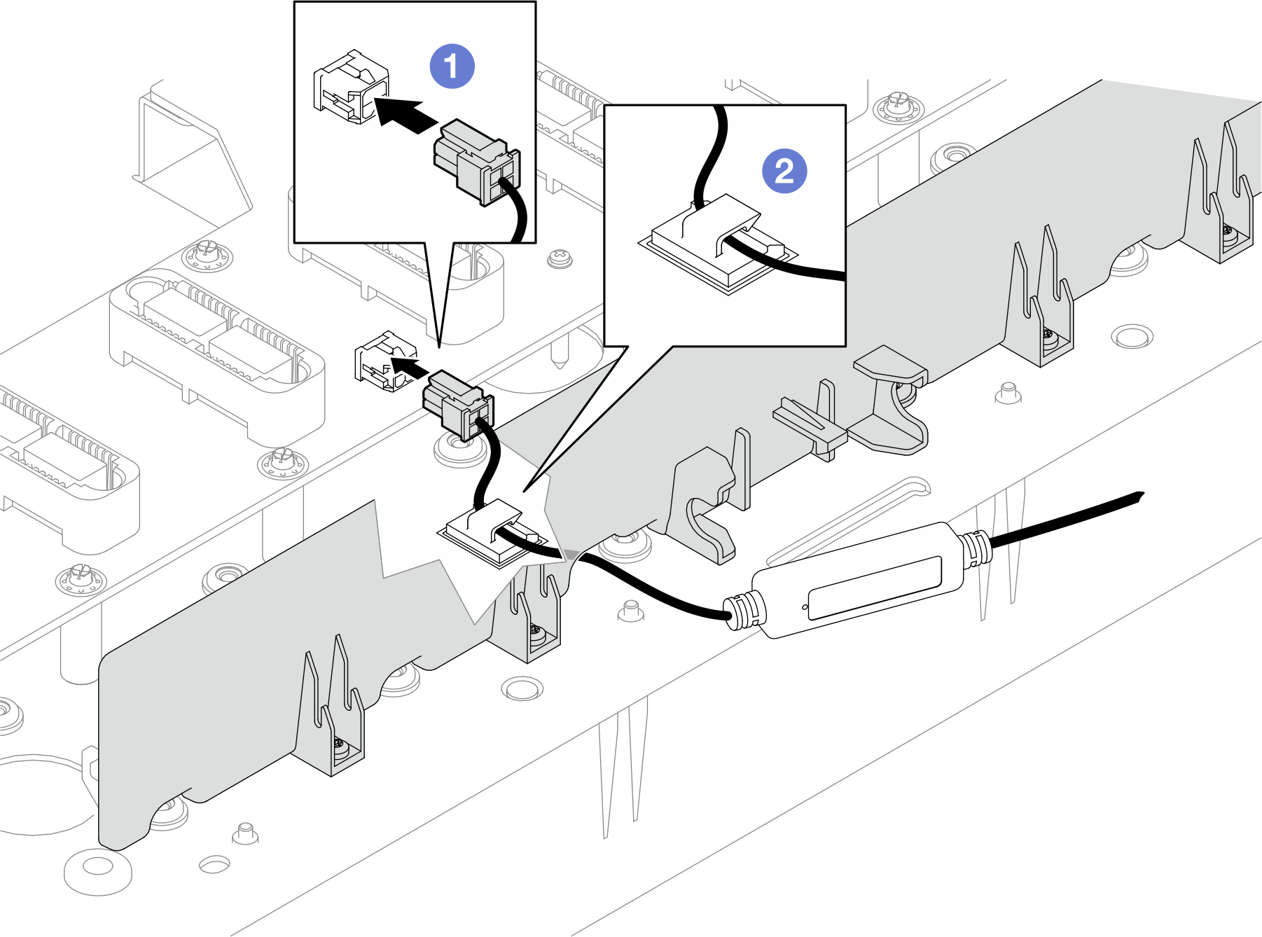
 A support bracket is attached to the bottom side of the drip tray. Align the leakage sensor module to the guide hole of the support bracket.
 Insert the leakage sensor module to the bracket.NoteKeep the side with LED light on the outside.Figure 2. Installing the leakage sensor module to the bracket
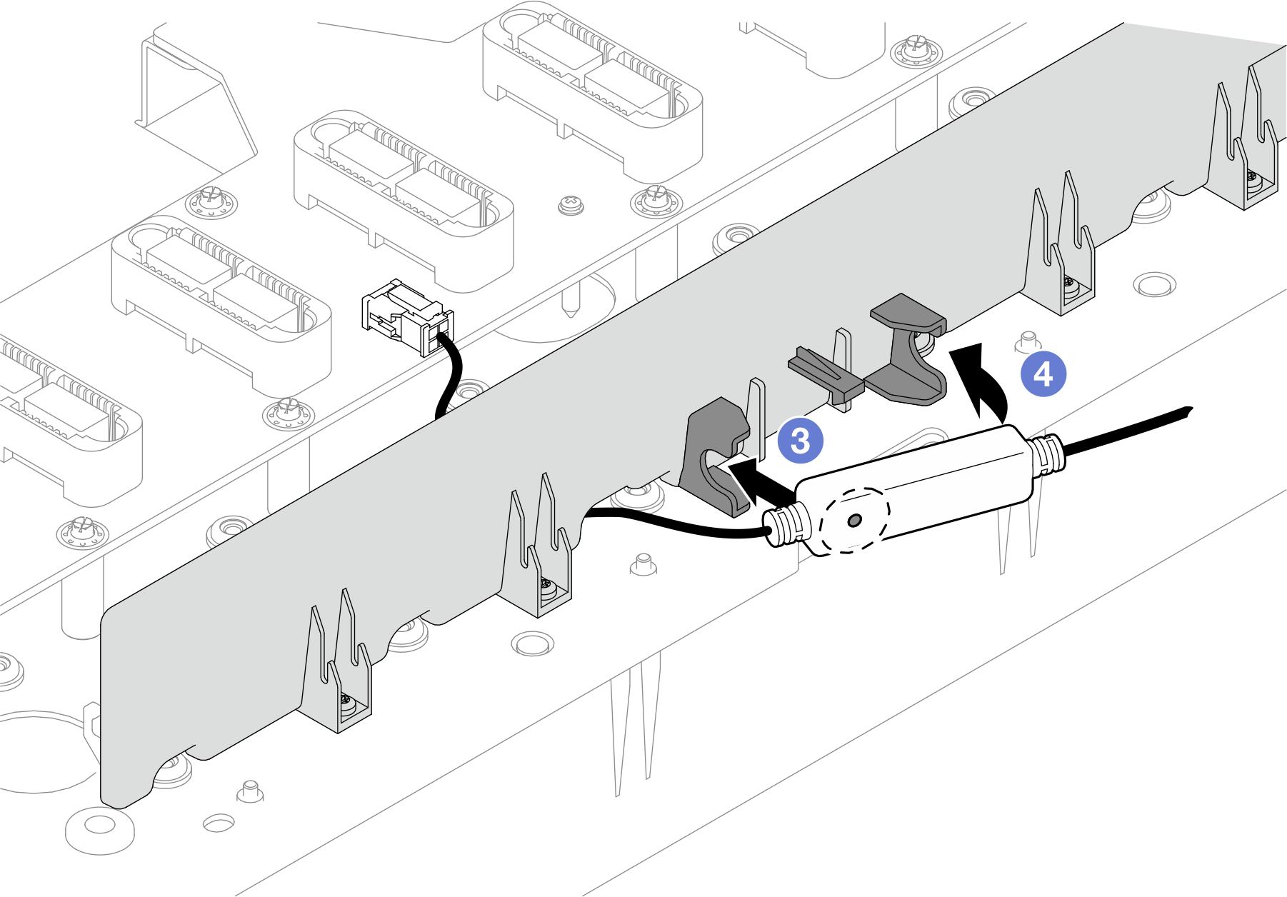
- Route the leakage sensor cable around the mid-plate.NoteWhen routing the cable, make sure to secure the cable to all the cable clips on the mid-plate assembly. See the following illustrations for cable clip types, locations, and quantity.Figure 3. Cable secured in various cable clips types
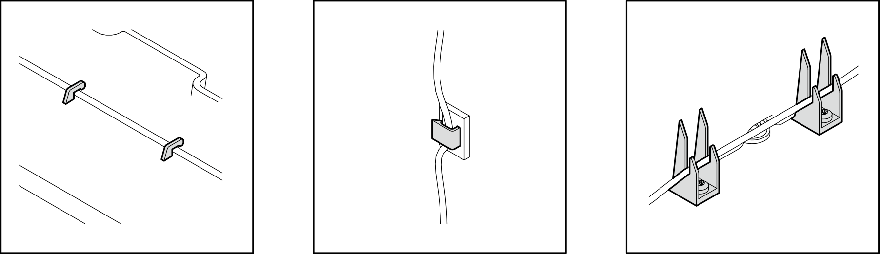 Figure 4. Cable clip quantity and location on the mid-plate
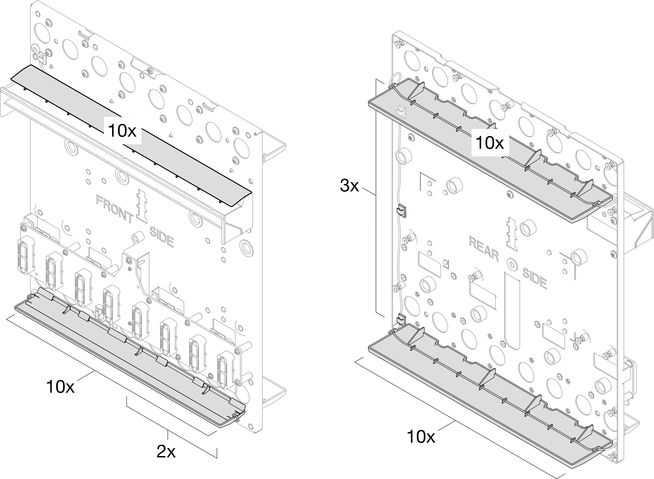
- Route the cable around the mid-plate following the sequence shown on the illustrations below.
- FRONT SIDE: (on the bottom-side of the drip tray) → → (through the guide hole on mid-plate
- REAR SIDE: →
 →
→  →
→  (through the guide hole on mid-plate)
Figure 5. Routing the cable around the mid-plate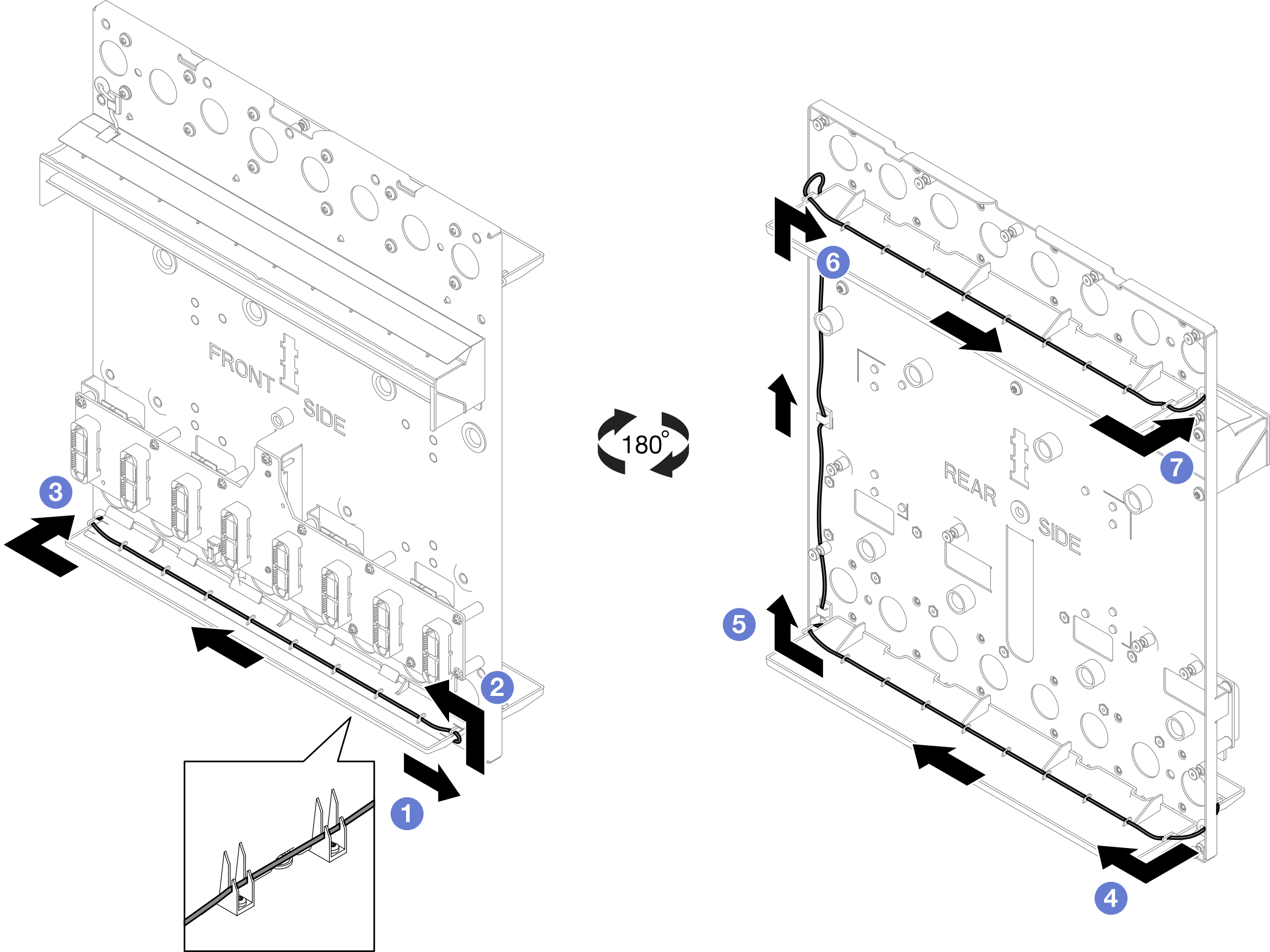
- FRONT SIDE:
- Route the cable around the mid-plate following the sequence shown on the illustrations below.
- From the top drip tray on the front side, secure the cable to the cable clip, and insert the cable through the opening on drip tray cover.Figure 6. Threading cable through the drip tray cover
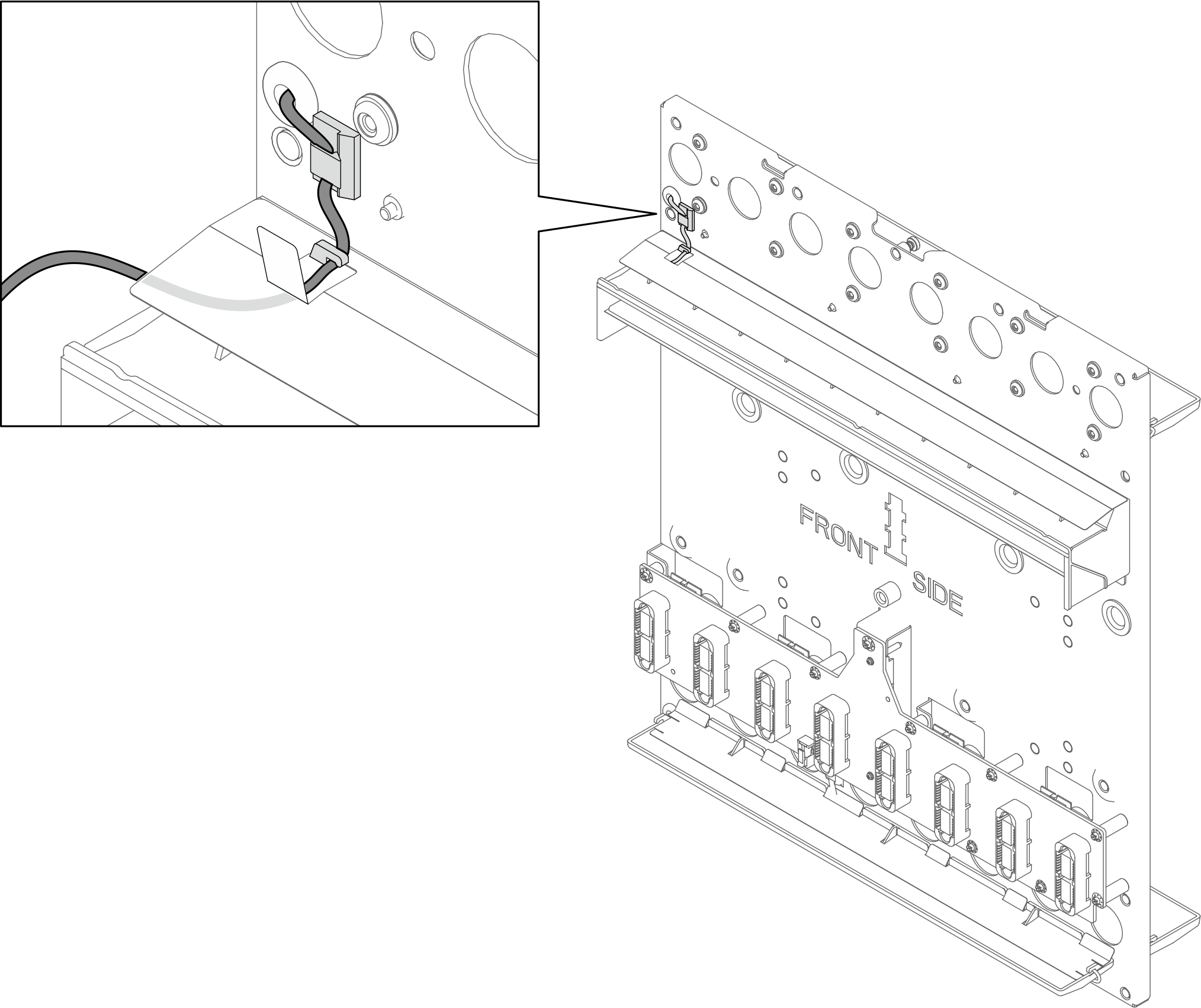
- Secure the cable to the top drip tray on the front side.
- Open the drip tray cover.
- Secure the cable to all the cable clips. Fold the cable to avoid the cable hanging from the drip tray.Figure 7. Securing leakage sensor cable to the top drip tray on the front side
After you finish
Install the enclosure mid-plate assembly. See Install the mid-plate assembly.
Install upper and lower manifold. See Install the manifold.
Install all Power Conversion Station (PCS) cage. See Install a Power Conversion Station (PCS) cage.
Install all Power Conversion Stations (PCS). See Install a Power Conversion Station (PCS).
Install the SMM3. See Install the SMM3.
Install the blank filler. See Install the blank filler.
Install all trays into the front of the enclosure. See Install a tray in the enclosure.
- Install any other required components.
- Connect all required cables.
- Connect the enclosure to power.
- Restart any nodes that you shut down. See Power on the solution.
- The SMM3 is powered-on automatically.