Install the power distribution board
Use this information to install the power distribution board.
About this task
Screwdriver for PH 1, PH 2, T10, and T30 screws
Waterloop Service Kit (SC750 V4) (The water loop carrier in the Service Kit is reusable, it is recommended to keep it at the facility where the server operates for future replacement needs.)
Up VR Gap Pad Kit (SC750 V4)
MID E3.S TOP Gap Pad (SC750 V4) , if E3.S middle drive is installed.
MID E3.S BOT Gap Pad (SC750 V4) , if E3.S middle drive is installed.
Storage Gap Pad Kit (SC750 V4) , if E3.S front drive is installed.
Storage Gap Pad Kit (SC750 V4) , if E3.S 1T dual front drives or E3.S 2T single front drive are installed.
CX7 NDR200 Gap Pad (SC750 V4) , if ConnectX-7 NDR 200 adapter is installed.
CX7 Gap Pad (SC750 V4) , if ConnectX-7 NDR 400 adapter is installed.
Read Installation Guidelines and Safety inspection checklist to ensure that you work safely.
The following illustration might differ slightly from your hardware, but the installation method is the same.
Go to Drivers and Software download website for ThinkSystem SC750 V4 to see the latest firmware and driver updates for your server.
Go to Update the firmware for more information on firmware updating tools.
- A video of this procedure is available at YouTube.
Procedure
- Install the bus bar connector module.
 Install the bus bar connector module to the tray rear bezel.
 Install three PH1 screws on the rear tray bezel.Figure 1. Installing the bus bar connector module
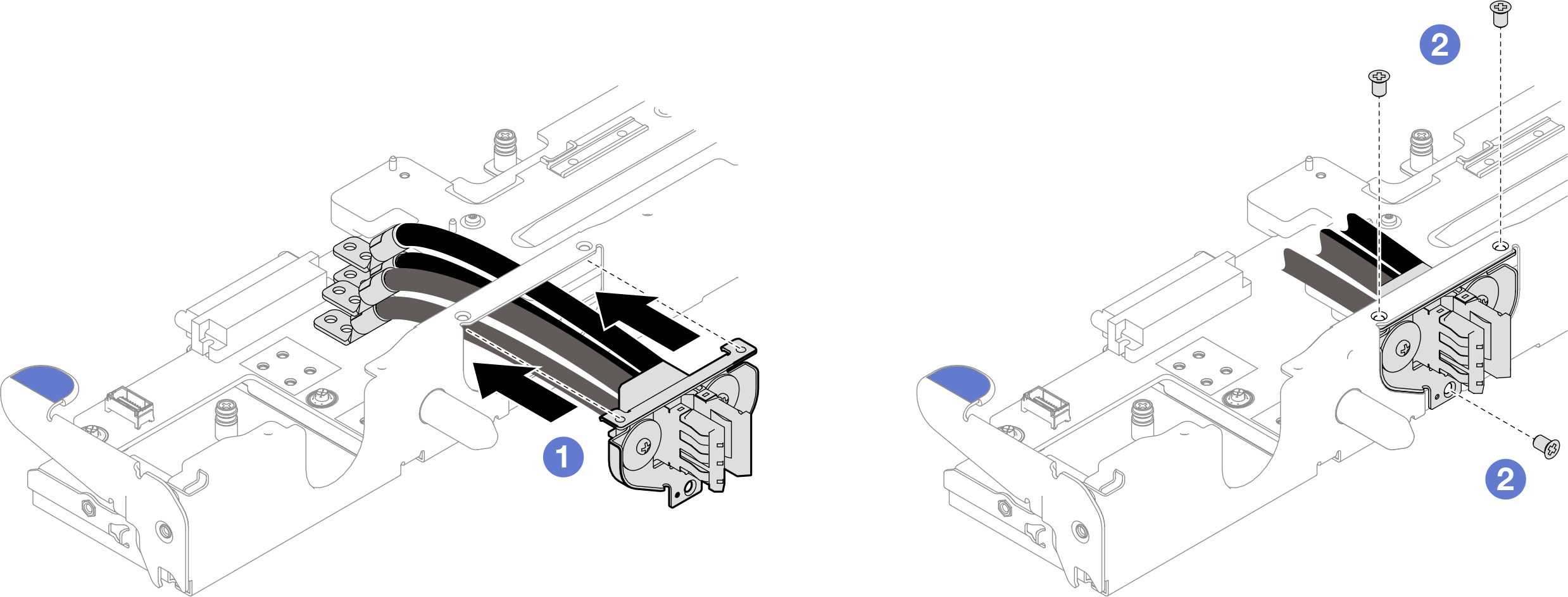
 Take the cables labeled as PWR and connect them to the power pad marked as PWR. Install four PH2 screws to secure the cables to the PIB, with a torque screwdriver set to the proper torque.
 Take the cables labeled as GND and connect them to the ground pad marked as GND. Install four PH2 screws to secure the cables to the PIB, with a torque screwdriver set to the proper torque.
NoteFor reference, the torque required for the screws to be fully tightened/removed is 7+/- 1.0 lbf-in.
Figure 2. Connecting the bus bar connector module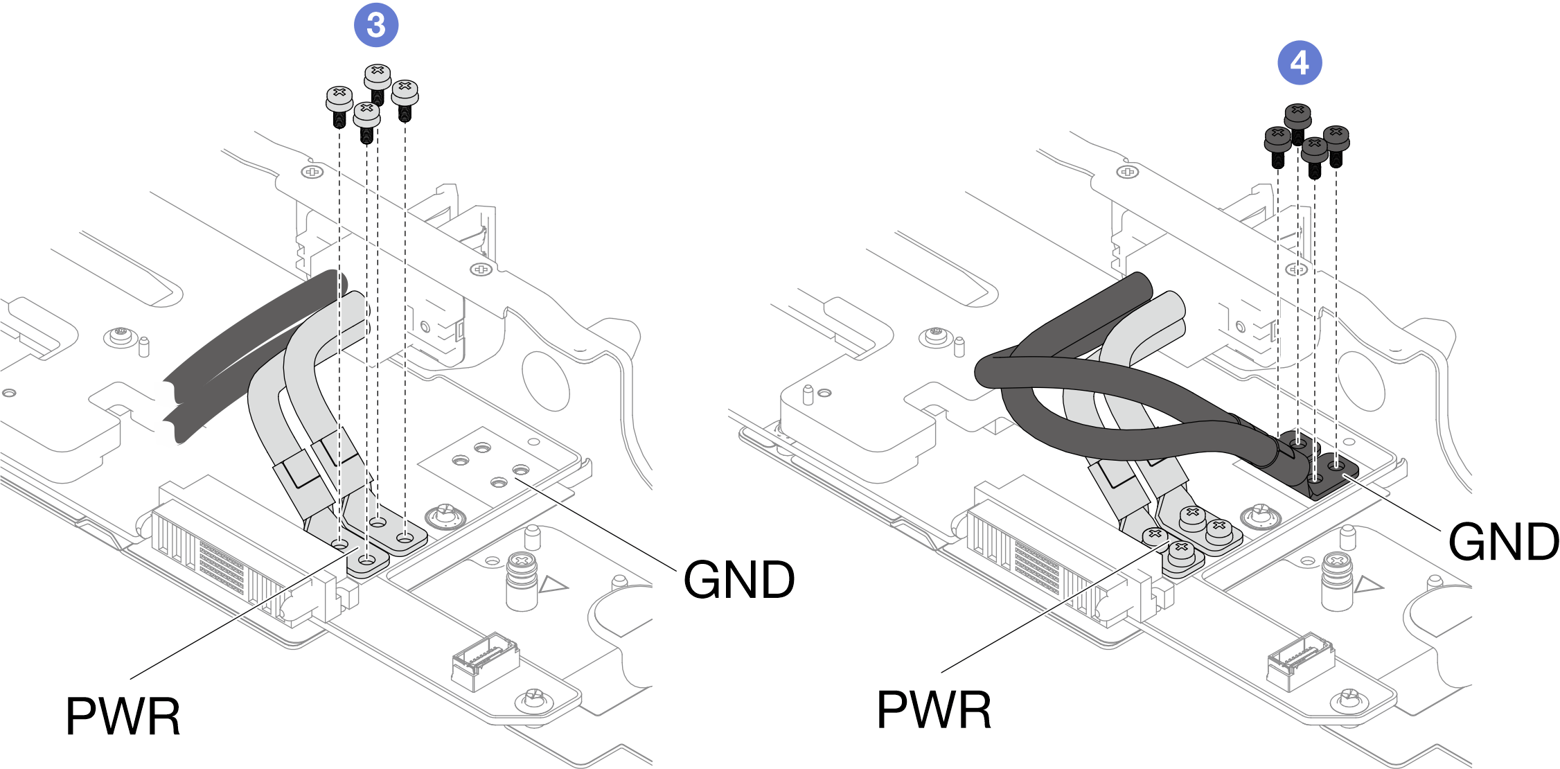
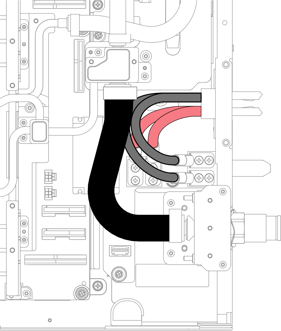
- Place one GND cable under the water loop tube, the other GND cable between the tube and the PWR cables, as the illustration below.Figure 3. GND cable arrangement
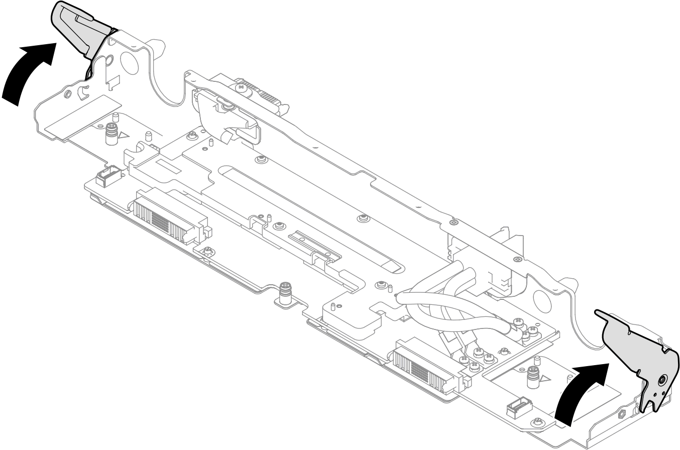
- Make sure the PDB tray handles are rotate to unlock position.Figure 4. PDB tray handle unlock position
- Install the PDB tray.
- Align the power connectors on PDB tray to the power connectors to the system boards.
- There are triangle markings on the inside of the right-side and left-side of the tray. Push the PDB tray into the server tray. Stop pushing when the PDB tray meets the triangle markings.
- Rotate both PDB tray handles at the same time to the lock position
AttentionMake sure to rotate both handles at the same time.Figure 5. Installing the PDB tray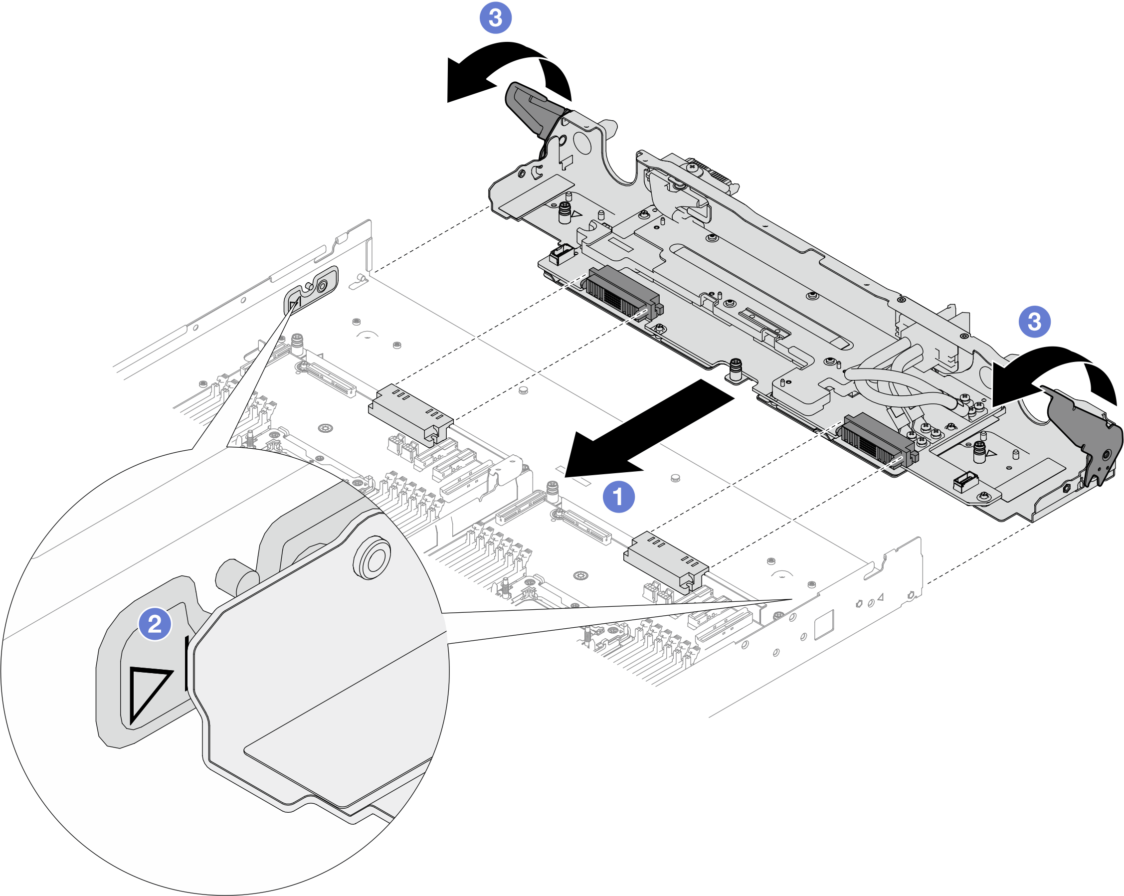
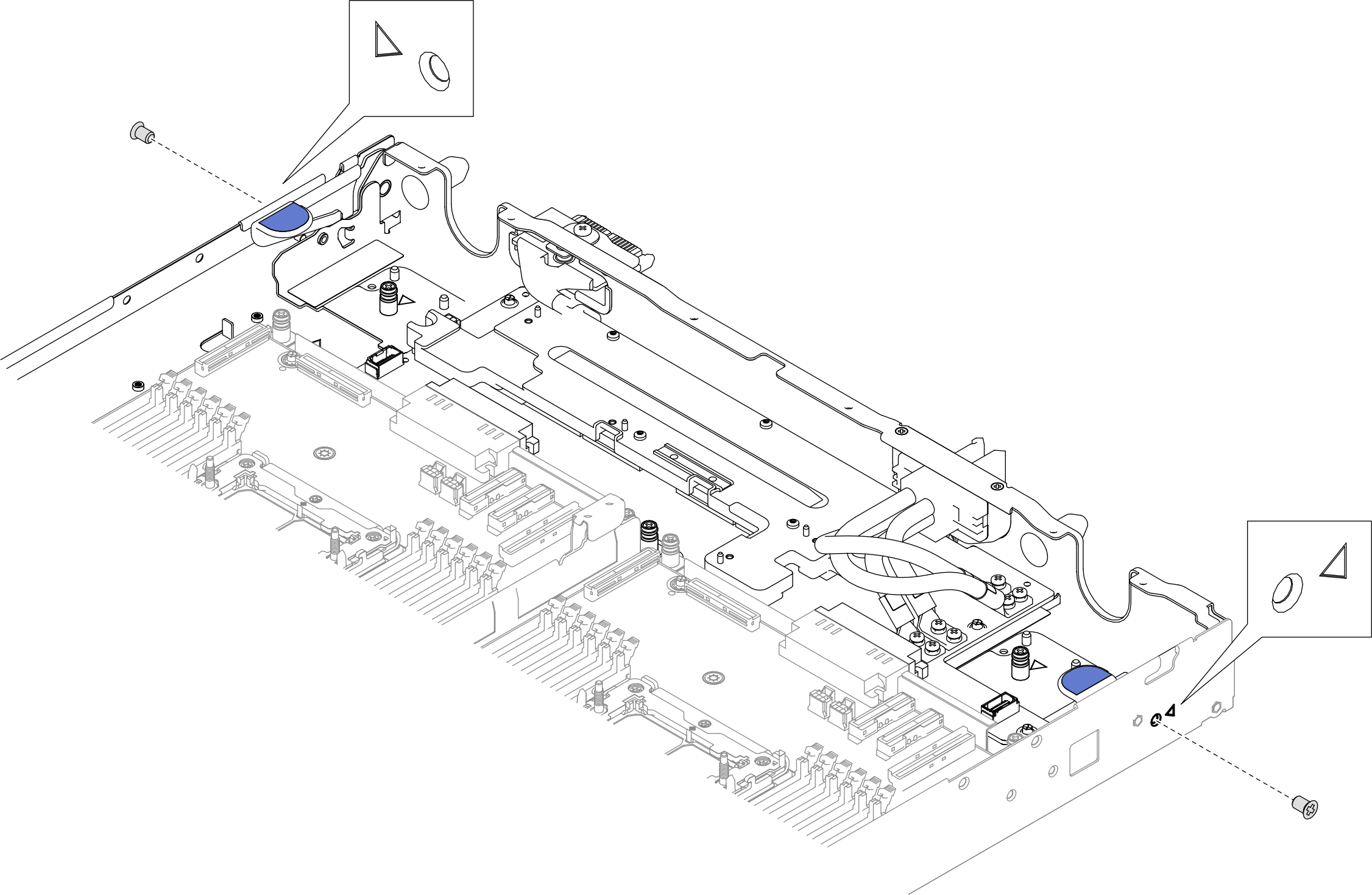
- Install two PH1 screws from the outside of the tray.Figure 6. Installing screws from the outside of the tray.
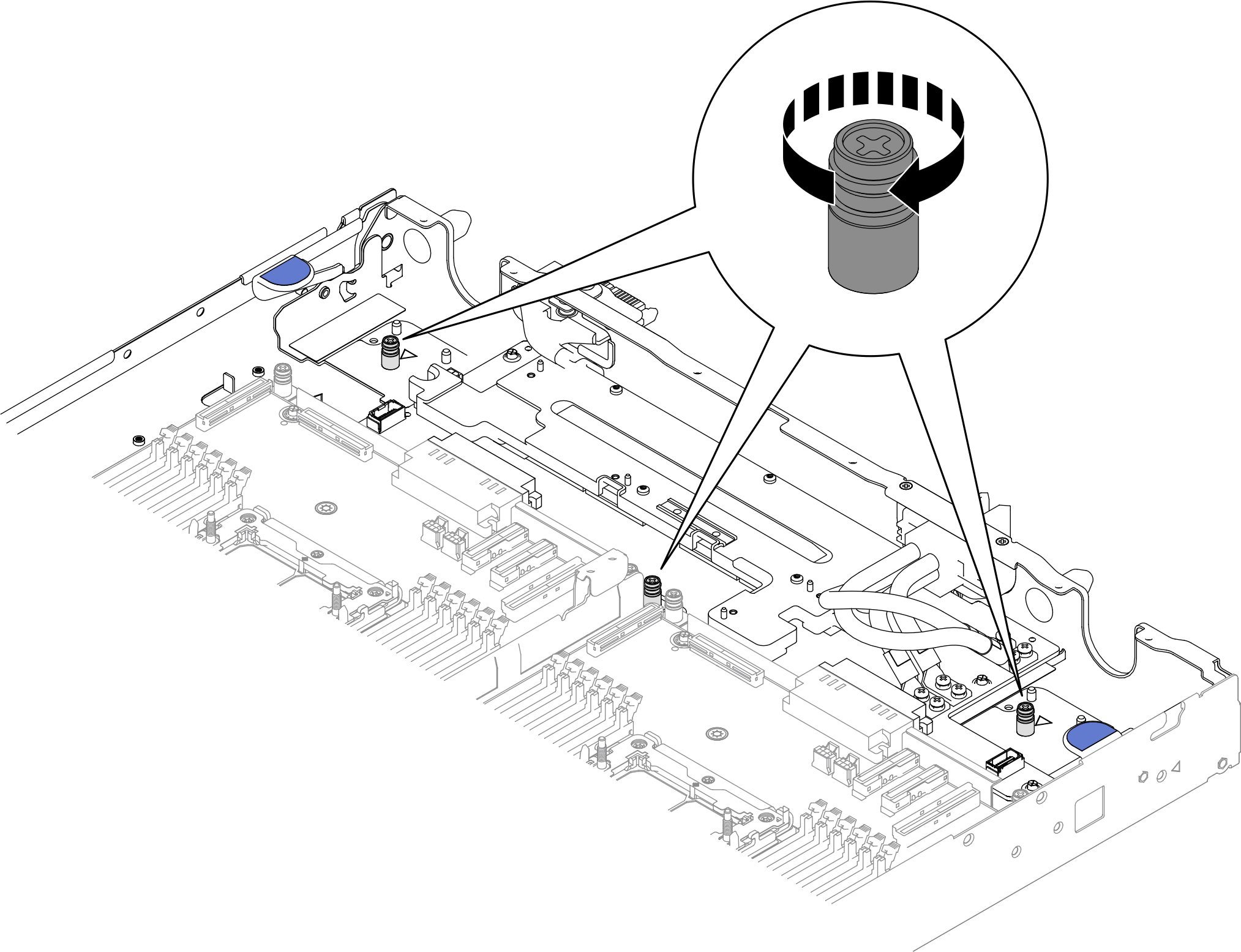
- Fasten the three PH1 captive screws to install the PDB tray to the server tray.Figure 7. Fastening captive screws
Install the water loop. See Install the water loop.
Install the leakage sensor. See Install the leakage sensor.
Install the sideband cable kit. See Install the system management sideband cable kit.
Install the middle E3.S drive cage. See Install an E3.S 1T middle drive cage assembly.
- Install the PCIe adapter riser cage. See Install a ConnectX-7 NDR 200 adapter riser assembly or Install a ConnectX-7 NDR 400 adapter riser assembly.
Install the front E3.S drive cage. See Install an E3.S front drive cage assembly.
If the system will be installed with memory modules that requires dual-side cooling, install DIMM cooling bars. See Install a DIMM cooling bar.
Install the cross braces. See Install the cross braces.
Install the memory module, perform one of the following.
Install the memory modules that require single-side cooling. See Install a memory module (single-side cooling)., or
Install the memory modules that require dual-side cooling. See Install a memory module (dual-side cooling).
Install the DIMM comb. See Install a DIMM comb.
Install the tray cover. See Install the tray cover.
Install the tray into the enclosure. See Install a tray in the enclosure.
- Connect all required external cables to the solution.NoteUse extra force to connect QSFP cables to the solution.
- Check the power LED on each node to make sure it changes from fast blink to slow blink to indicate all nodes are ready to be powered on.Note
Shared I/O configuration requires specific nodes power-on sequence. When powering on the system, power on Node B first; then, power on Node A. For more information, see PCIe adapter cable routing.