Remove the system I/O board (DC-SCM)
Use this information to remove the system I/O board. System I/O board is also known as Datacenter-ready Secure Control Module (DC-SCM).
About this task
Screwdriver for M3 PH1, PH 1, PH 2, T10, and T30 screws
Waterloop Service Kit (SC750 V4) (The water loop carrier in the Service Kit is reusable, it is recommended to keep it at the facility where the server operates for future replacement needs.)
Up VR Gap Pad Kit (SC750 V4)
MID E3.S TOP Gap Pad (SC750 V4) , if E3.S middle drive is installed.
MID E3.S BOT Gap Pad (SC750 V4) , if E3.S middle drive is installed.
Storage Gap Pad Kit (SC750 V4) , if E3.S front drive is installed.
Storage Gap Pad Kit (SC750 V4) , if E3.S 1T dual front drives or E3.S 2T single front drive are installed.
CX7 NDR200 Gap Pad (SC750 V4) , if ConnectX-7 NDR 200 adapter is installed.
CX7 Gap Pad (SC750 V4) , if ConnectX-7 NDR 400 adapter is installed.
Read Installation Guidelines and Safety inspection checklist to ensure that you work safely.
Turn off the corresponding DWC tray that you are going to perform the task on.
Disconnect all external cables from the enclosure.
Use extra force to disconnect QSFP cables if they are connected to the solution.
To avoid damaging the water loop, always use the water loop carrier when removing, installing or folding the water loop.
The following illustration might differ slightly from your hardware, but the installation method is the same.
After replacing the system I/O board, update the firmware to the specific version supported by the server. Make sure that you have the required firmware or a copy of the pre-existing firmware before you proceed.
- A video of this procedure is available at YouTube.
Procedure
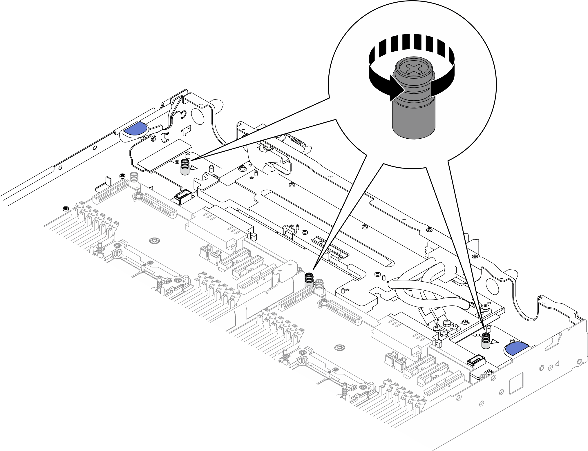
- Unfasten three PH1 captive screws on the power distribution board tray (PDB tray).Figure 1. Unfasten three captive screws
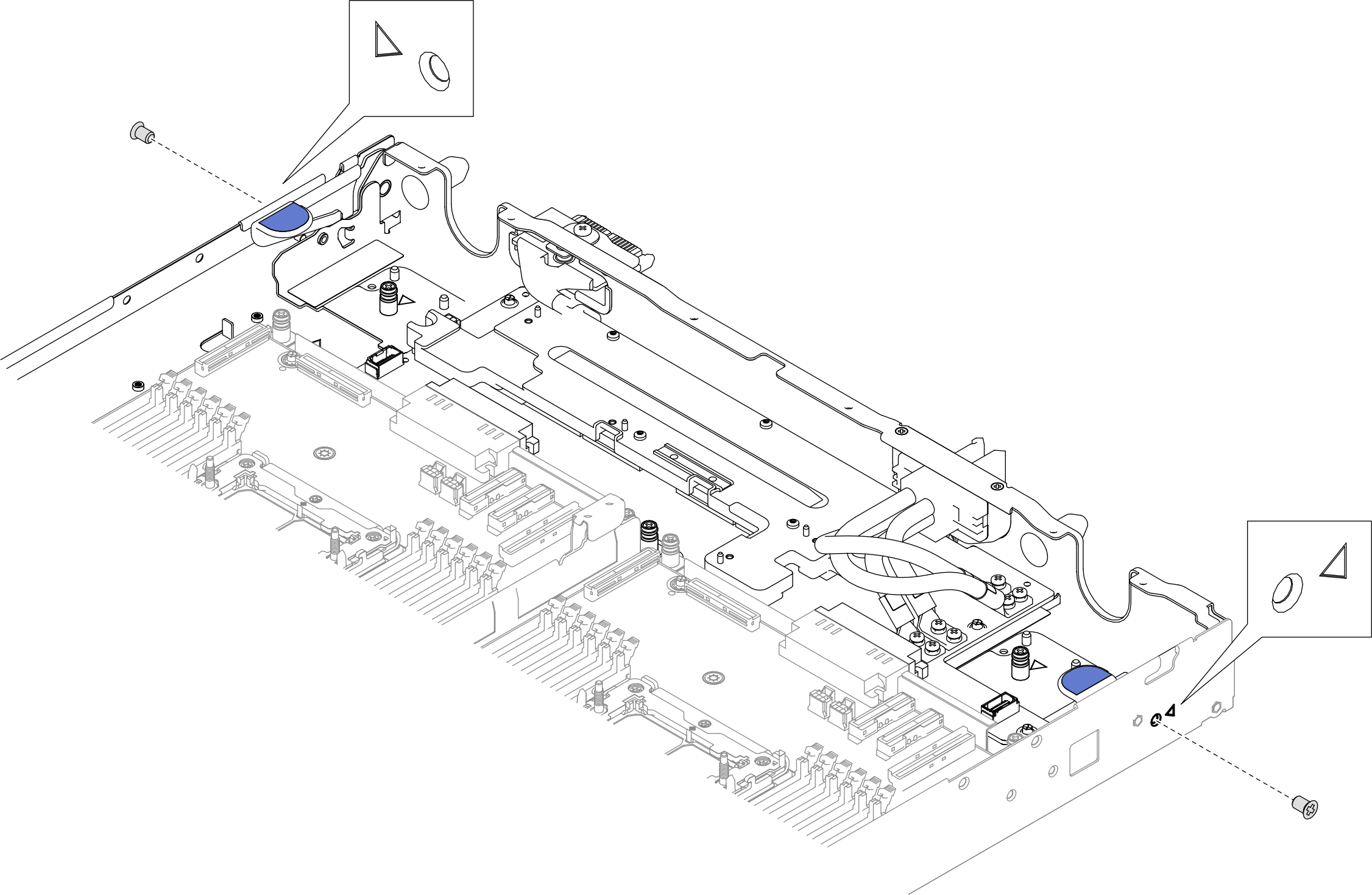
- Remove two PH1 screws from the sides of the tray.Figure 2. Removing screws from outside of the tray.
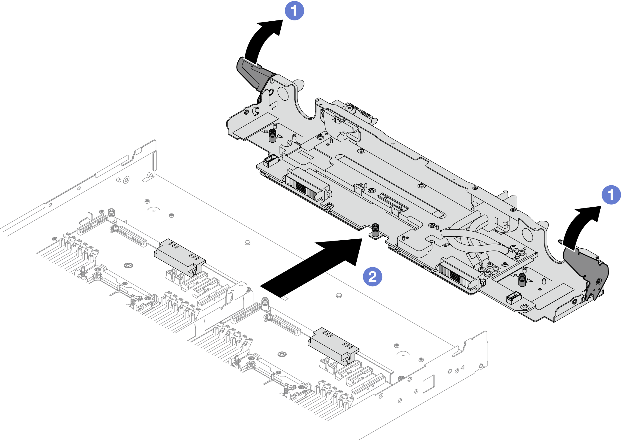
- Remove the power distribution board tray (PDB tray) from the server tray.
 Rotate the tray handles to unlock position.
 Remove the PDB tray from the server tray.
- Remove the system-board assembly from the tray.NoteHold the system-board assembly by the thumbscrew in the front and the tab beside the power connector.Figure 3. Holding the system-board assembly
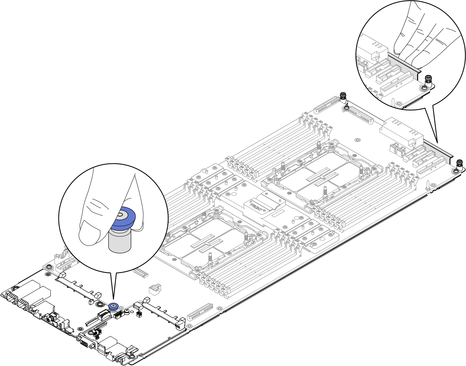
- Loosen the two screws in the rear of they system-board assembly.
- Pull up the plunger in the front to release the system-board assembly.
 Remove the system-board assembly from the tray.
Figure 4. Removing the system-board assembly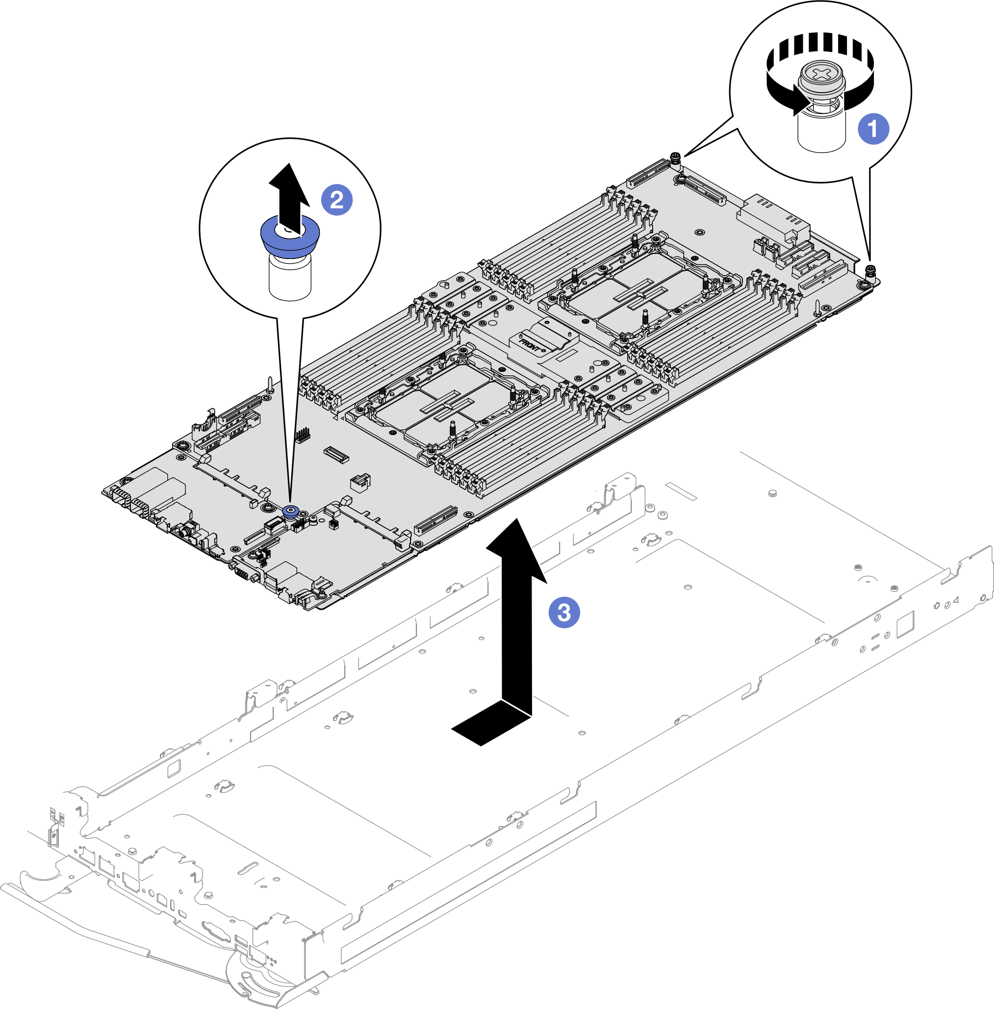
- Disconnect the COM port cable from the front I/O board and the system I/O board.
1 Serial log connector on front I/O board 2 COM port connector on system I/O board Figure 5. Removing COM port cable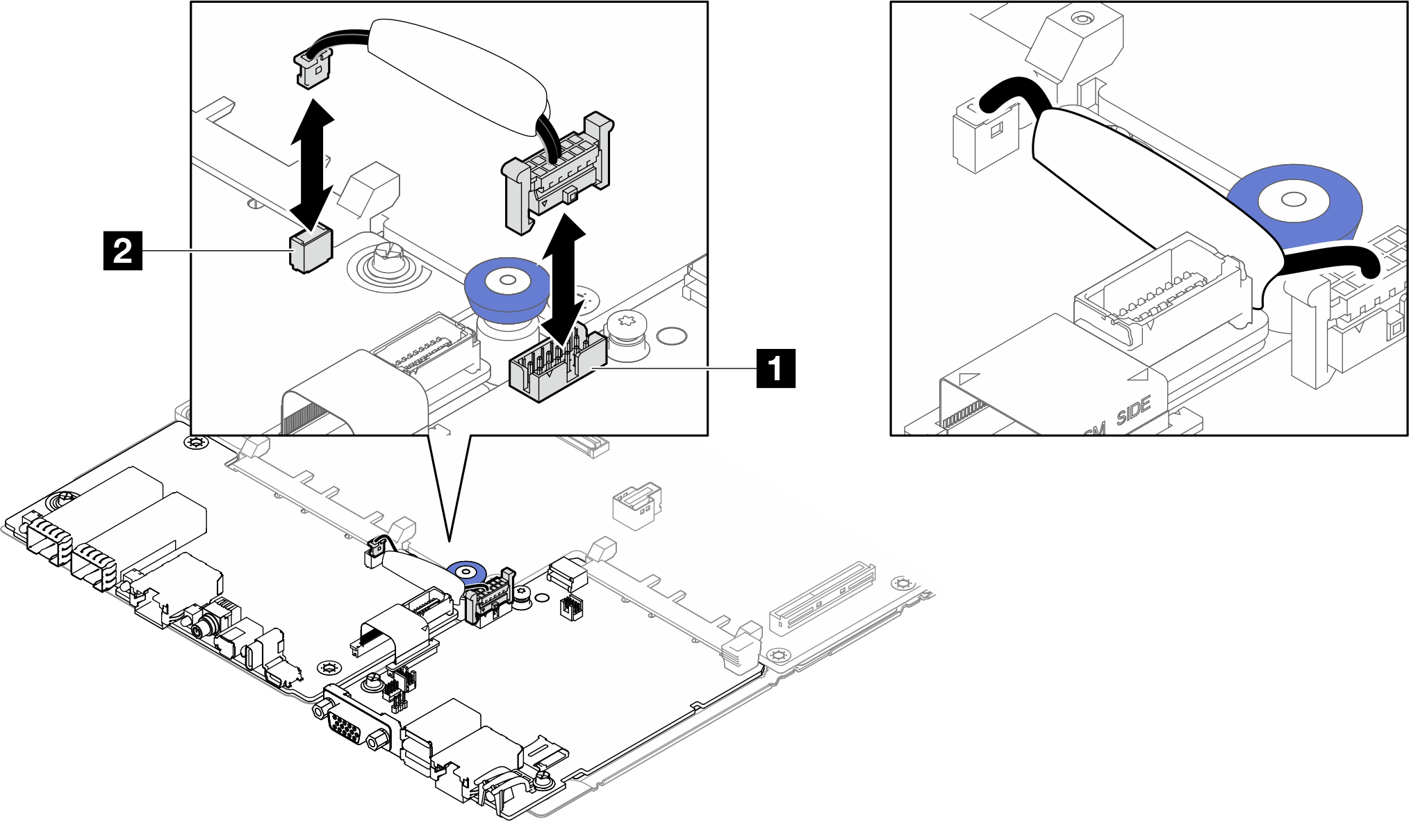
- Remove the FPC cable.
- Pull up the latches of the connectors on the front I/O board and the system I/O board.Figure 6. Pulling up connector latches
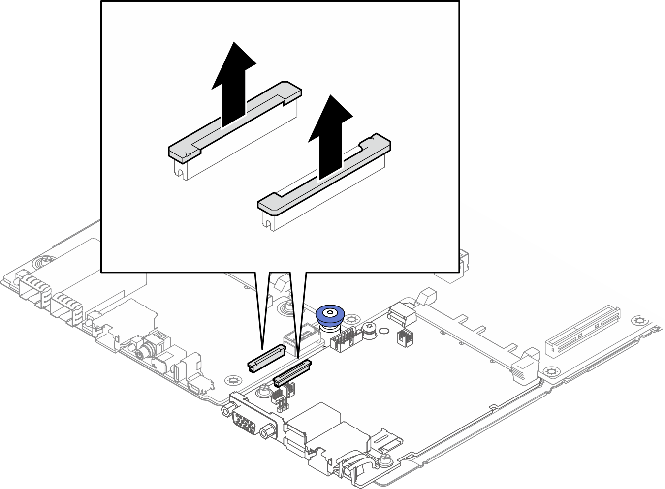
- Disconnect the FPC cable from the front I/O board and the system I/O board.
FPC cable connection to FIO board and system I/O board From To FPC cable end marked as FIO SIDE → FIO SIDE connector on Front I/O board FPC cable end marked as SCM SIDE → PHY CONN connector on system I/O board Figure 7. FPC cable connection
- Pull up the latches of the connectors on the front I/O board and the system I/O board.
- Remove the system I/O board.
- Remove two M3 PH1 screws from the system I/O board.
- Remove the system I/O board from the system board assembly.
Figure 8. Removing the system I/O board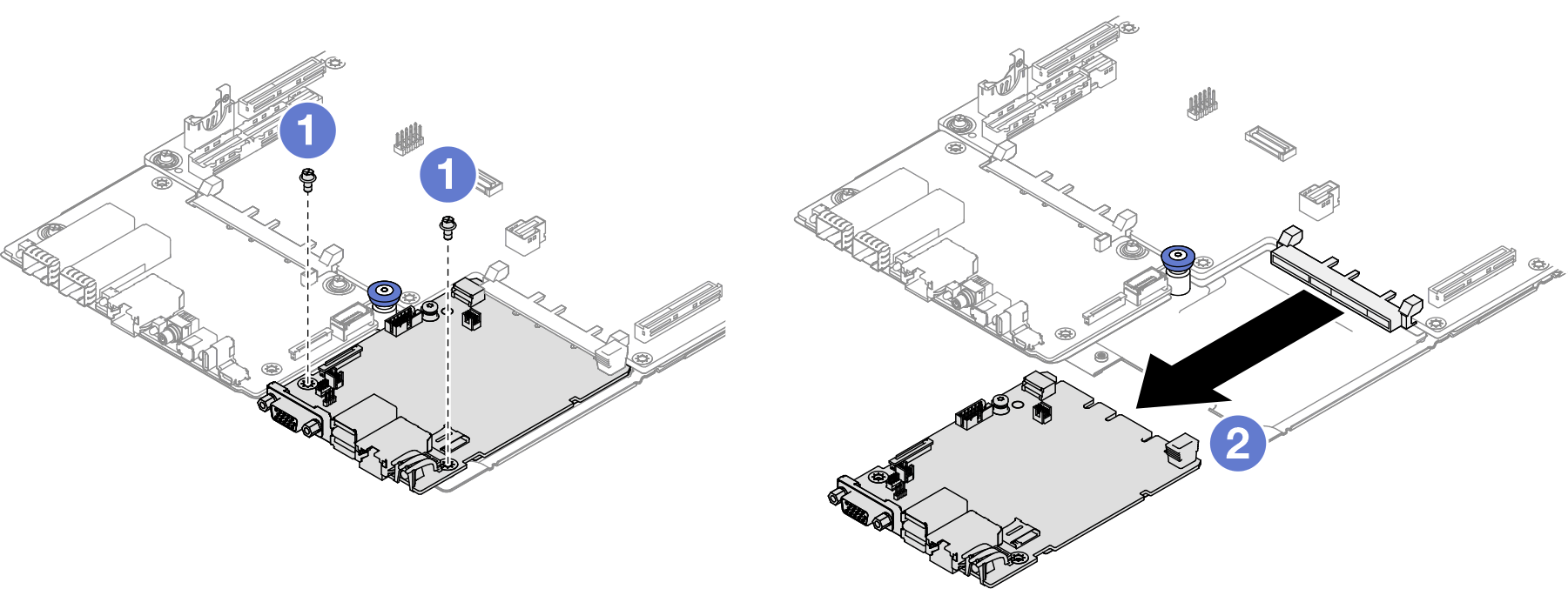
If you are instructed to return the component or optional device, follow all packaging instructions, and use any packaging materials for shipping that are supplied to you.