Install a system board (Trained technician only)
Follow instructions in this section to install a system board.
About this task
This task must be operated by trained technicians that are certified by Lenovo Service. Do not attempt to remove or install the part without proper training and qualification.
To avoid potential danger, make sure to read and follow the safety information.
Read Installation Guidelines and Safety inspection checklist to make sure that you work safely.
Prevent exposure to static electricity, which might lead to system halt and loss of data, by keeping static-sensitive components in their static-protective packages until installation, and handling these devices with an electrostatic-discharge wrist strap or other grounding system.
After replacing the system board, always update the server with the latest firmware or restore the pre-existing firmware.
Go to Drivers and Software download website for ThinkSystem SD550 V3 to see the latest firmware and driver updates for your server.
Go to Update the firmware for more information on firmware updating tools.
Procedure
- Install the system board to the node.ImportantWhen installing the system board into the node, avoid touching the connectors on the system board. Do not damage any surrounding components inside the node.
- Carefully hold the rear edge of the system board and tilt the system board at angle.
- Align the connectors of the system board and the front of the node; then, gently slide and insert the system board into place.
- Carefully seat the system board onto the corresponding guide pins and screw holes in the node.
NoteMake sure that the standoffs are securely seated in the holes of the system board.Figure 1. Installation of the system board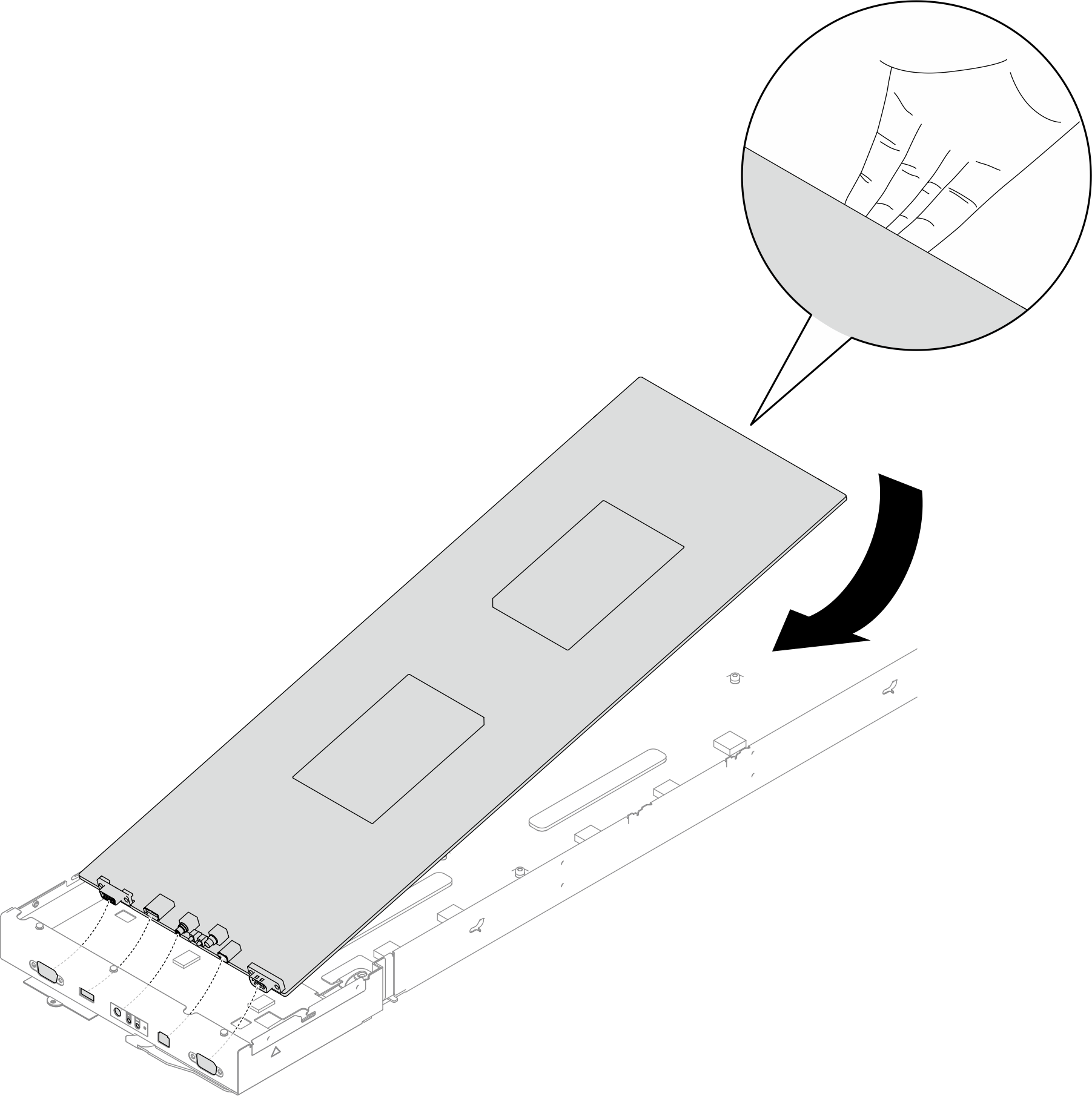
- Tighten all the system-board screws on the front of the node and on the system board.Figure 2. Installation of the system-board screws on the front
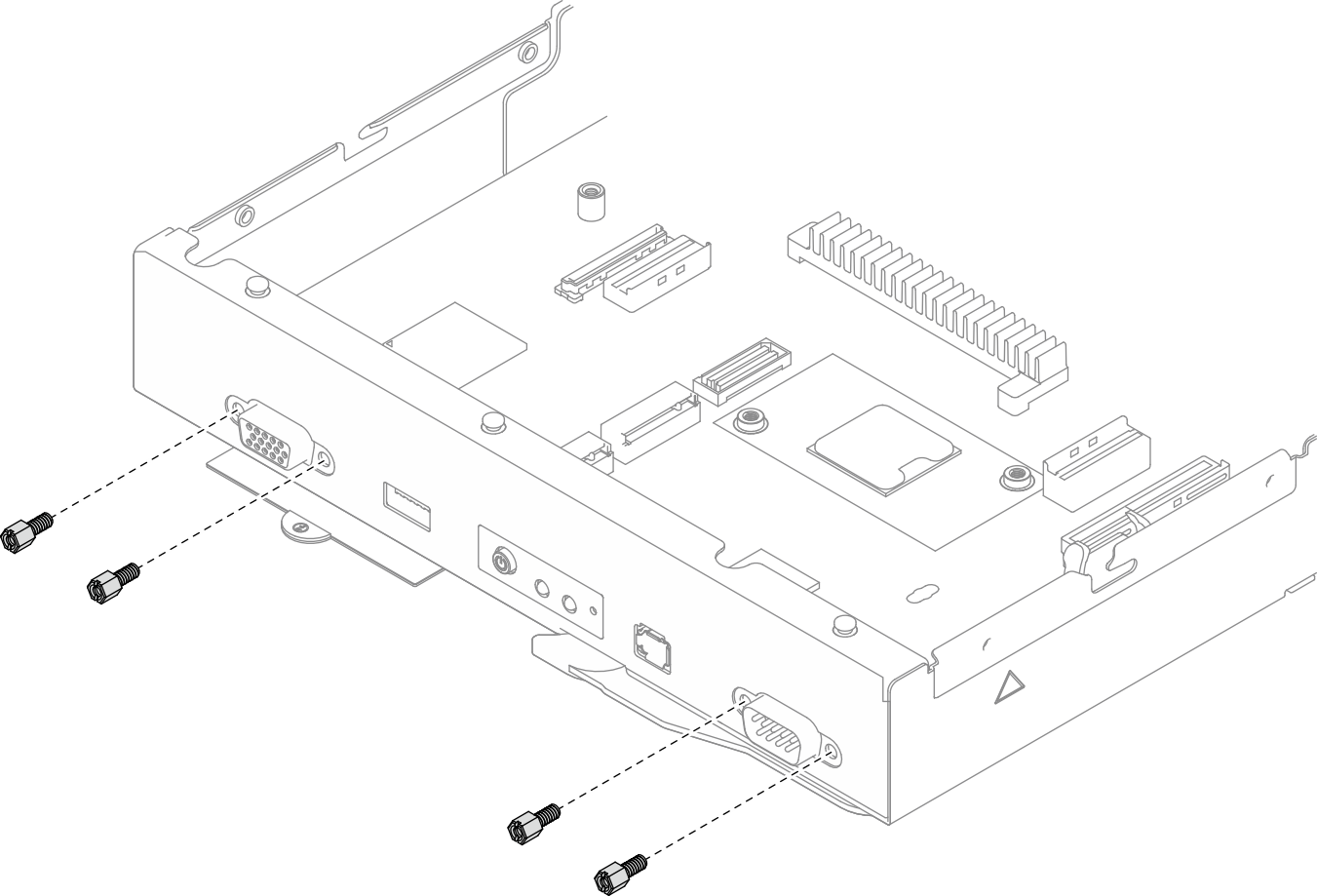 Figure 3. Installation of the screws on the system board
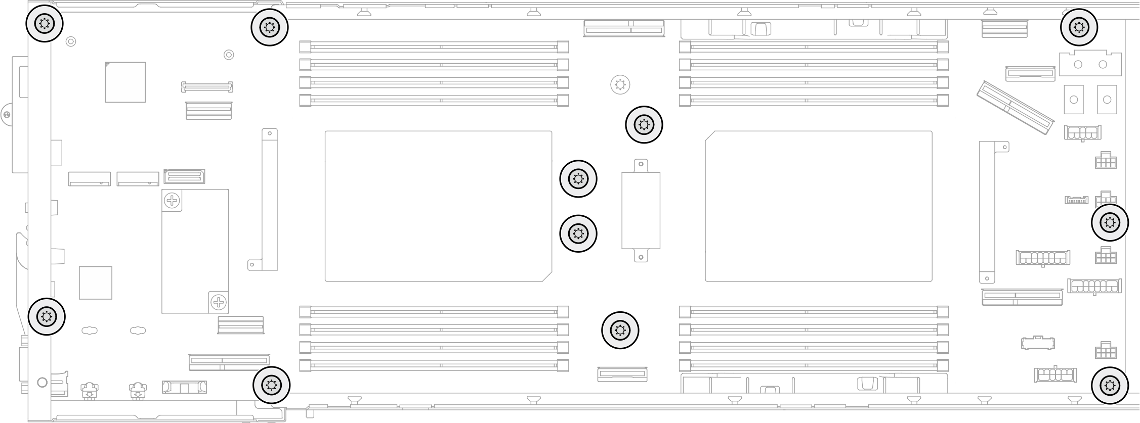
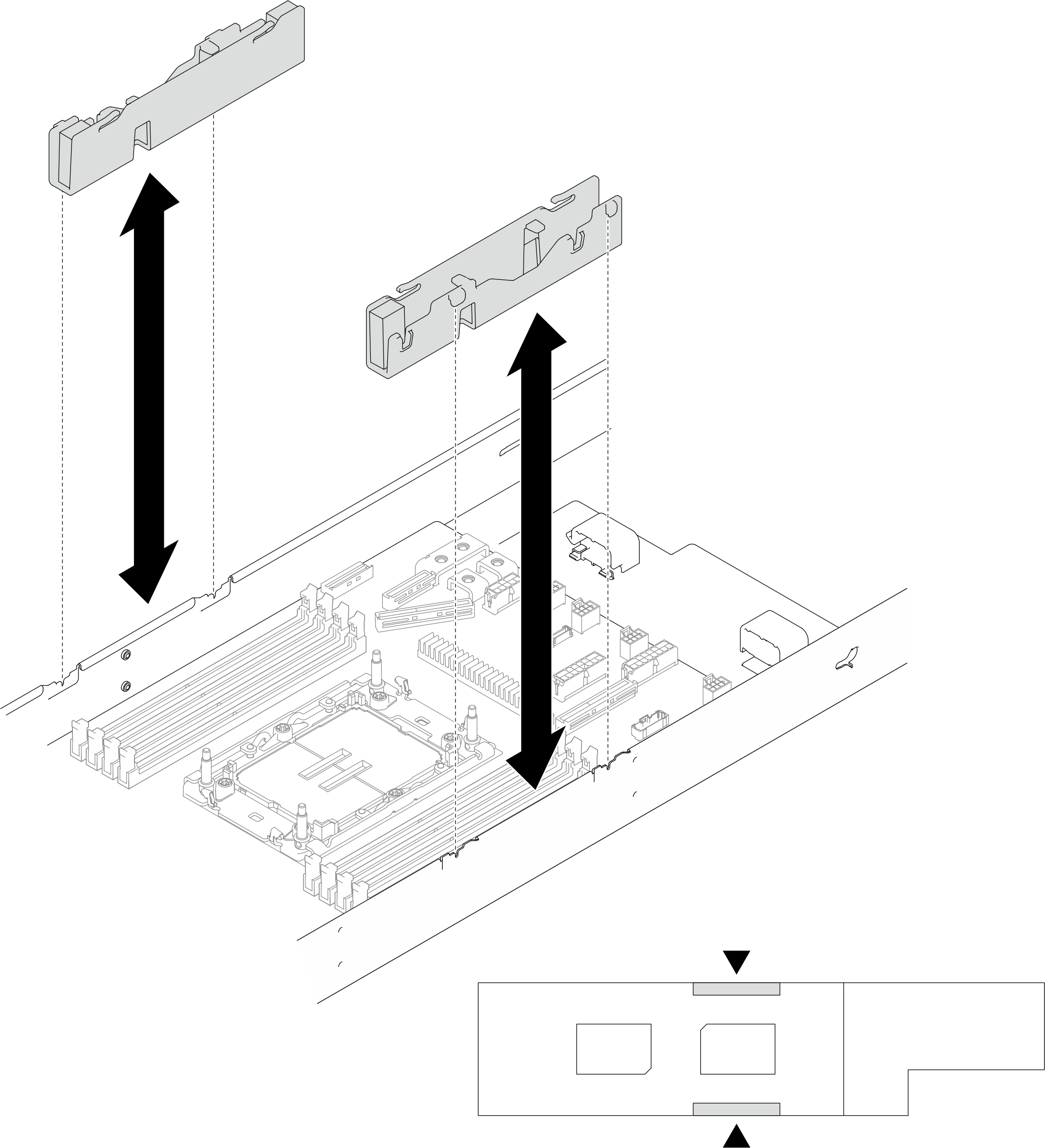
- If necessary, reinstall the cable ducts as illustrated.Figure 4. Cable duct replacement
After you finish
- Reinstall the side bracket(s) (see Install a side bracket).
- If necessary, install the rear I/O module and rear OCP cable to the node (see Install a rear I/O module and Install a power distribution board); then, connect cables of the rear I/O module and OCP cable to the system board (see Rear I/O and OCP module cable routing).
- If necessary, install the power distribution board and connect cables between the power distribution board and the system board (see Install a power distribution board and Power distribution board cable routing).
- Reinstall the power bus bar (see Install a power bus bar).
- If necessary, reinstall the PCIe riser assembly to the node and reconnect the required PCIe cables to the system board (see Install a PCIe riser assembly and PCIe riser cable routing).
- Reinstall the fan cage to the node and reconnect all the fan cables to the system board (see Install a fan cage).
- If necessary, reinstall the GPU air duct (see Install a GPU air duct).
- If necessary, reinstall the internal adapter bracket and reconnect all the required cables to the internal adapter (see Install an internal adapter bracket and 2.5-inch drive backplane cable routing ).
- Reinstall the required M.2 drives to the system board (see Install an M.2 drive).
- Reinstall the MicroSD card to the system board (see Install a MicroSD card).
- Reinstall the firmware and RoT security module to the system board (see Install a firmware and RoT security module).
- Reinstall all the required memory modules or memory module fillers (see Install a memory module).
- If there is no CMOS battery (CR2032) installed on the system board yet, install one (see Install a CMOS battery (CR2032)).
- Reconnect all the required cables to the system board (see Internal cable routing).
- Reinstall the required front or rear air baffle (see Install an air baffle).
- Reconnect all the required cables to the drive backplane; then, reinstall the drive cage assembly to the node (see 2.5-inch drive backplane cable routing and Install a drive cage assembly).
- If necessary, reinstall the flash power module and reconnect the flash power module cable (see Install a flash power module).
- Reinstall all drives and drive fillers (if any) to the node (see Install a hot-swap drive).
- Reinstall the required processor and heat sink modules (PHMs) (see Install a processor and heat sink).
- If necessary, install the rear air baffle (see Install an air baffle).
- Make sure that all the required cables are routed and connected correctly; then, reinstall the top cover (see Install the top cover).
- Reinstall the node into the chassis (see Install a node to the chassis).
- Make sure that the required power supply units are installed and power cords are connected; then, power on the node (see Install a hot-swap power supply and Power on the node).
- Proceed to complete the parts replacement (see Complete the parts replacement).
- Update the vital product data (VPD). See Update the Vital Product Data (VPD). Machine type number and serial number can be found on the ID label, see Identify the system and access the Lenovo XClarity Controller.
- If hiding TPM or updating TPM firmware is needed, see Hide/observe TPM or Update the TPM firmware.
- Optionally, enable UEFI Secure Boot. See Enable UEFI Secure Boot.
- Download and install the latest device drivers: Drivers and Software download website for ThinkSystem SD550 V3.
- Update the system and device firmware. See Update the firmware.NoteIf you have replaced the firmware and RoT security module, update the firmware to the specific version supported by the server. See Tip for replacing a Firmware and RoT Security Module (Lenovo service technicians only).
Demo video