Transfer the system board
Use this information to transfer the system board to another tray.
About this task
To identify the gap pad/putty pad location and orientation, see:
Required Tools list in the following section.
Before replacing the gap pad/putty pad, gently clean the interface plate or the hardware surface with an alcohol cleaning pad.
Hold the gap pad/putty pad carefully to avoid deformation. Make sure no screw hole or opening is blocked by the gap pad/putty pad material.
Do not use expired putty pad. Check the expiry date on putty pad package. If the putty pads are expired, acquire new ones to properly replace them.
Required tools
Make sure you have the required tools listed below in hand to properly replace the component.
SD665 V3 Water Loop Service Kit (The water loop carrier in the Service Kit is reusable, it is recommended to keep it at the facility where the server operates for future replacement needs.)
SD665 V3 Water Loop Putty Pad Kit
VR 1.5mm Putty Pad
VR 2.5 mm Putty Pad
Putty pad cannot be reused. Whenever a component is removed, putty pads must be replaced with new ones before reinstalling the component.
Drive gap pad or putty pad kits according to the drives installed in the tray. See their respective replacement procedures for more information.
ConnectX series adapter putty pad kits according to the ConnectX adapter installed in the tray. See their respective replacement procedures for more information.
Screws and screwdrivers
Prepare the following screwdrivers to ensure you can install and remove corresponding screws properly.Screwdriver Type Screw Type Torx T10 head screwdriver Torx T10 screw Torx T20 head screwdriver Torx T20 screw Phillips #1 head screwdriver M3 screw Phillips #2 head screwdriver Phillips #2 screw 3/16" hex head screwdriver M3 screw
Read Installation Guidelines and Safety inspection checklist to ensure that you work safely.
Turn off the corresponding DWC tray that you are going to perform the task on.
Disconnect all external cables from the enclosure.
Use extra force to disconnect QSFP cables if they are connected to the solution.
To avoid damaging the water loop, always use the water loop carrier when removing, installing or folding the water loop.
Go to Drivers and Software download website for ThinkSystem SD665 V3 to see the latest firmware and driver updates for your server.
Go to Update the firmware for more information on firmware updating tools.
Procedure
- Reinstall the system board to the tray.
If the system board is with shielding cables, follow the procedures in Transferring system board with shielding cables.
If the system board is without shielding cables, follow the procedures in Transferring system board without shielding cables.
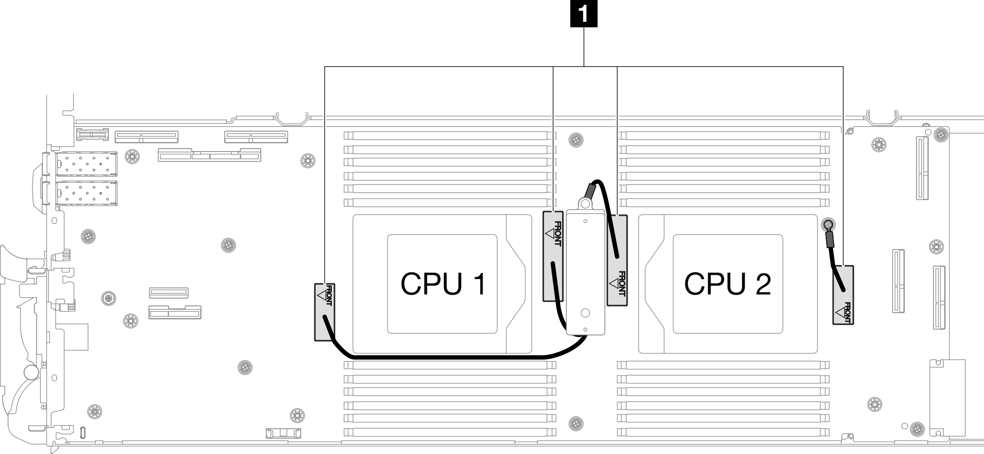
1 Shielding cables
Transferring system board with shielding cables
- Replace the VR conduction plate putty pads. Make sure to follow Gap pad/putty pad replacement guidelines.
 With an alcohol cleaning pad, remove the residual putty pad from the VR conduction plate removed previously. The putty pads are on the bottom side of the VR conduction plate.
 Paste the VR 2.5 mm Putty Pad to the bottom side of the VR conduction plate.Figure 1. Replacing the VR conduction plate putty pads
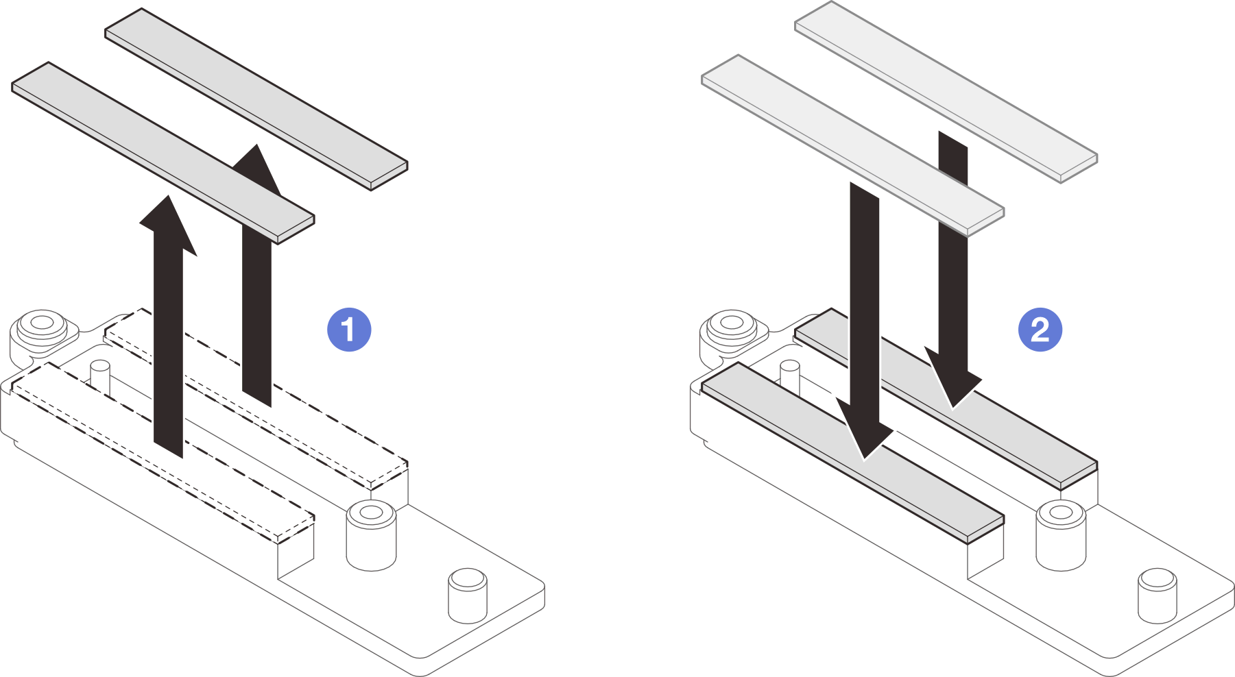
- Install the system board.
- Carefully hold the front guide pin and tilt the system board at an angle.
- Align the connectors with the corresponding holes on the front of the node; then, gently slide the system board forward.
NoteAvoid touching the connectors on the system board. Be careful not to damage any surrounding components inside the node.Figure 2. System board installation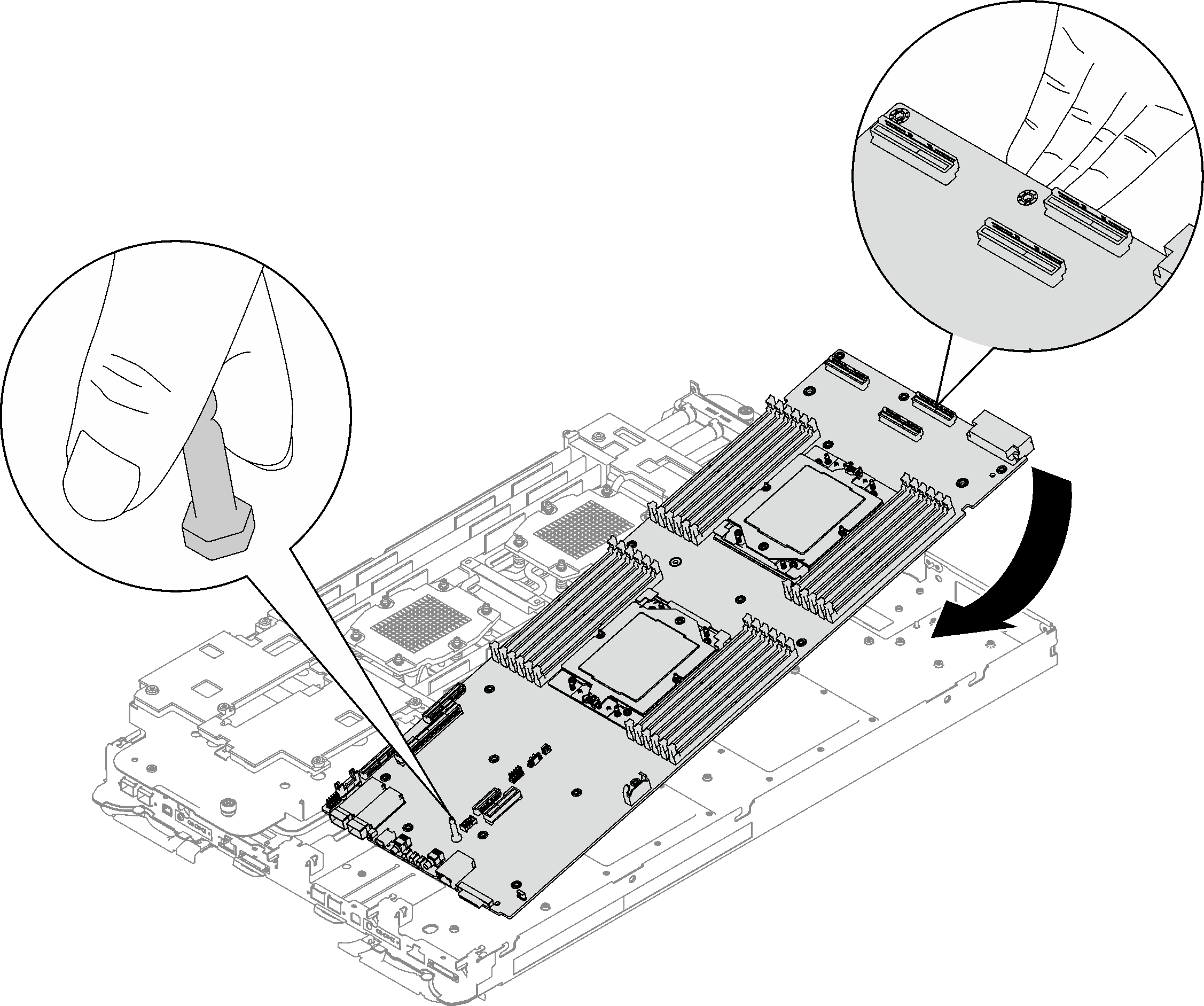
- Install the VR conduction plate.
- Keep the FRONT marking on the VR conduction plate pointing the front of the tray. Then, place the VR conduction plate on top of the two cable ring terminals.Note
A putty pad is attached to the bottom side of the VR conduction plate. Carefully hold the VR conduction plate to avoid damaging the putty pad.
Figure 3. Aligning VR conduction plate, shielding cables, and system board screw holes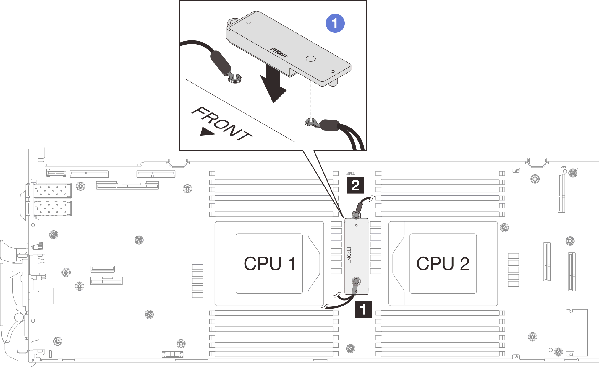
- Slightly press down the VR conduction plate.AttentionThe following items will be secured by screw. Make sure they are aligned and do not block each other.
Screw hole on the system board
The hole on the ring terminal of the shielding cage cable
Screw hole on the VR conduction plate
Figure 4. Pressing on the VR conduction plate
 While pressing down the VR conduction plate, place the screws into the two screw holes on the VR conduction plate. Then, fasten the two screws to secure the cables to the system board. DO NOT fasten the screws until both screws are placed into the VR conduction plate.Figure 5. Installing shielding cable 1/2 and 3
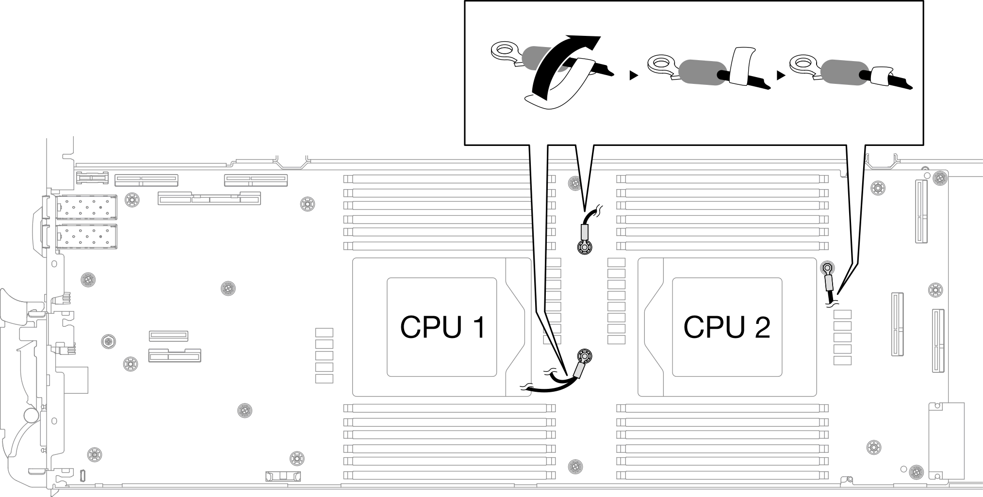
- Locate the screw hole for braided cable 4. Then, align shielding cable 4 to the screw holes on system board as shown below. Make sure the ring terminal of the cable is placed in the angle shown below. Fasten the screw to secure the shielding cable to the system board.
1 Screw hole for shielding cable 4 Figure 6. Location of screw hole of shielding cable 4 Figure 7. Installing shielding cable 4
- There are labels attached to shielding cable 1, 3, and 4. Roll the label around the cable all the way through to prevent label interfering with system connectors and water loop.Figure 8. Rolling label around the shielding cable
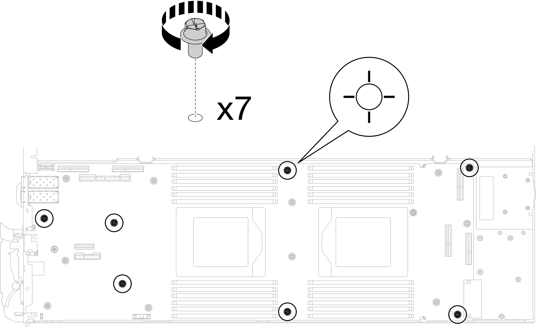
- Install and tighten seven M3 screws per node on the system board with a 3/16" hex head screwdriver set to the proper torque.NoteFor reference, the torque required for the screws to be fully tightened/removed is 5.0+/- 0.5 lbf-in, 0.55+/- 0.05 N-M.Figure 9. System board screws installation
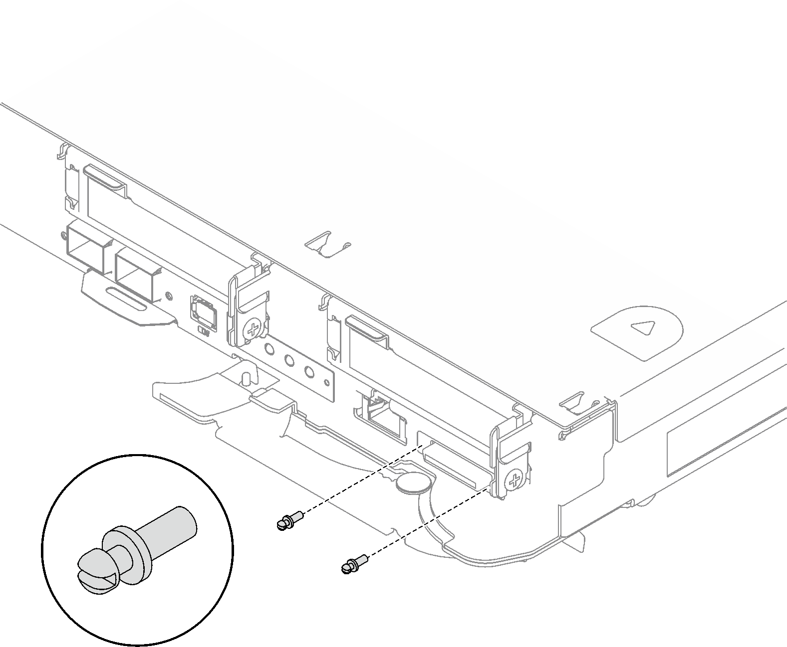
- Install the two KVM screws to the front of the node with a torque screwdriver set to the proper torque.NoteFor reference, the torque required for the screws to fully tightened/removed is 1.3+/-0.5 lb-in, 0.15+/- 0.05 N-M.Figure 10. KVM screws installation
Transferring system board without shielding cables
- Replace the VR conduction plate putty pads. Make sure to follow Gap pad/putty pad replacement guidelines.
- With an alcohol cleaning pad, remove the residual putty pad from the VR conduction plate removed previously. The putty pads are on the bottom side of the VR conduction plate.
- Paste the VR 1.5mm Putty Pad to the bottom side of the VR conduction plate.Figure 11. Replacing the VR conduction plate putty pads
- Align the VR conduction plate with the holes on the system board; then, fasten the two M3 screws (per node).Note
A putty pad is attached to the bottom side of the VR conduction plate. Carefully hold the VR conduction plate to avoid damaging the putty pad.
Figure 12. VR conduction plate installation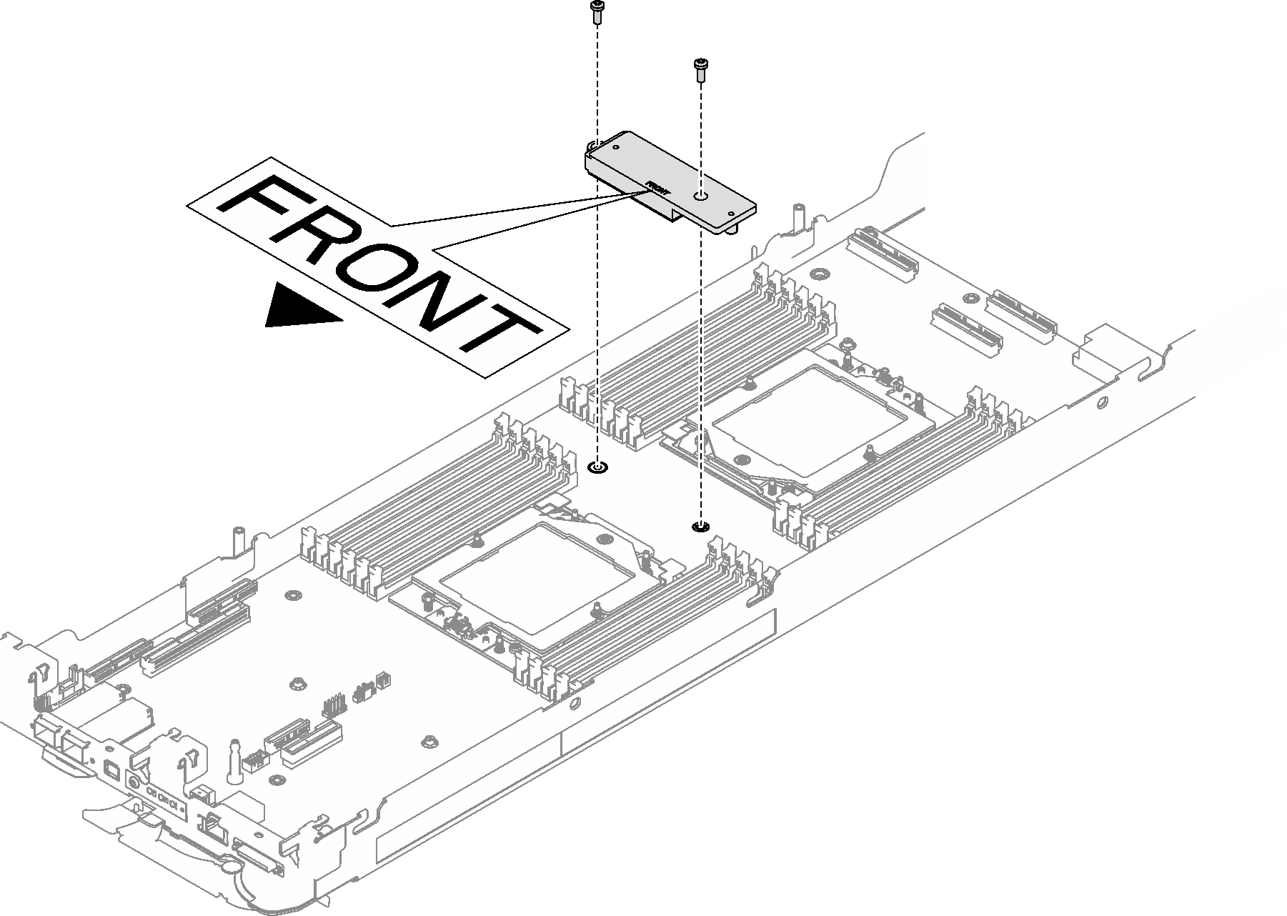
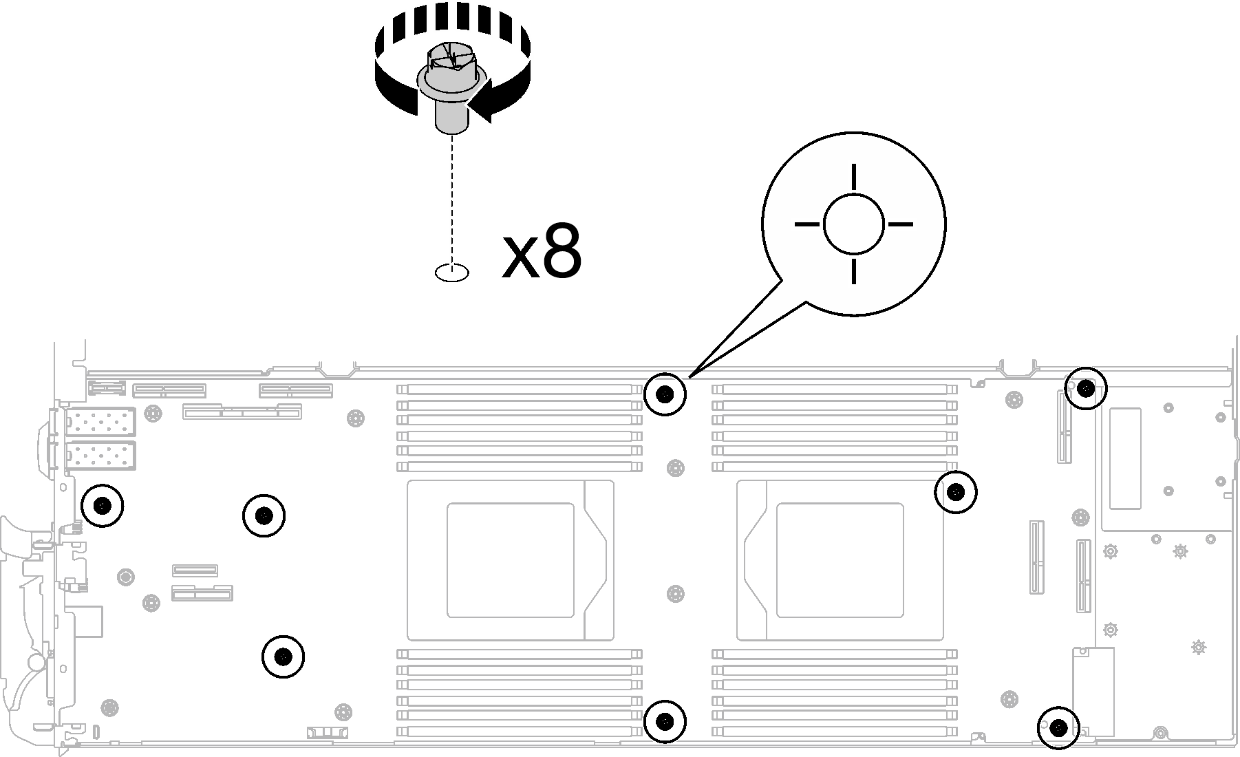
- Install and tighten eight M3 screws per node on the system board with a 3/16" hex head screwdriver set to the proper torque.NoteFor reference, the torque required for the screws to be fully tightened/removed is 5.0+/- 0.5 lbf-in, 0.55+/- 0.05 N-M.Figure 13. System board screws installation
- Install the two KVM screws to the front of the node with a torque screwdriver set to the proper torque.NoteFor reference, the torque required for the screws to fully tightened/removed is 1.3+/-0.5 lb-in, 0.15+/- 0.05 N-M.Figure 14. KVM screws installation
Install the power distribution board. See Install the power distribution board.
Install the processor. See Install a processor.
Install the PCIe riser assembly. See Install a PCIe riser assembly (ConnectX-6) , Install a PCIe riser assembly (ConnectX-7 NDR 200), or Install a PCIe riser assembly (ConnectX-7 NDR 400).
Install the drive cage. See Install a drive cage assembly.
Install the M.2 backplane assembly. See Install the M.2 backplane assembly.
Install the memory modules. See Install a memory module.
Install the DIMM comb. See Install a DIMM comb.
Install the cross braces. See Install the cross braces.
Install the tray cover. See Install the tray cover.
Install the tray into the enclosure. See Install a DWC tray in the enclosure.
- Connect all required external cables to the solution.NoteUse extra force to connect QSFP cables to the solution.
Check the power LED on each node to make sure it changes from fast blink to slow blink to indicate all nodes are ready to be powered on.
Update the vital product data (VPD). See Update the Vital Product Data (VPD).
Machine type number and serial number can be found on the ID label, see Identify the solution and access the Lenovo XClarity Controller.
Enable TPM/TCM. See Enable TPM.
If hiding TPM or updating TPM firmware is needed, see Hide/observe TPM or Update the TPM firmware.
Optionally, enable UEFI Secure Boot. See Enable UEFI Secure Boot.