Install a processor
This task has instructions for installing a processor. This task requires Torx 10 driver, T20 driver, Philips #1 driver, and Philips #2 driver.
About this task
To identify the gap pad/putty pad location and orientation, see:
Required Tools list in the following section.
Before replacing the gap pad/putty pad, gently clean the interface plate or the hardware surface with an alcohol cleaning pad.
Hold the gap pad/putty pad carefully to avoid deformation. Make sure no screw hole or opening is blocked by the gap pad/putty pad material.
Do not use expired putty pad. Check the expiry date on putty pad package. If the putty pads are expired, acquire new ones to properly replace them.
Required tools
Make sure you have the required tools listed below in hand to properly replace the component.
SD665 V3 Water Loop Service Kit (The water loop carrier in the Service Kit is reusable, it is recommended to keep it at the facility where the server operates for future replacement needs.)
SD665 V3 Water Loop Putty Pad Kit
Putty pad cannot be reused. Whenever the water loop is removed, putty pads must be replaced with new ones before reinstalling the water loop.
Drive gap pad or putty pad kits according to the drives installed in the tray. See their respective replacement procedures for more information.
ConnectX series adapter putty pad kits according to the ConnectX adapter installed in the tray. See their respective replacement procedures for more information.
Screws and screwdrivers
Prepare the following screwdrivers to ensure you can install and remove corresponding screws properly.Screwdriver Type Screw Type Torx T10 head screwdriver Torx T10 screw Torx T20 head screwdriver Torx T20 screw Phillips #1 head screwdriver Phillips #1 screw Phillips #2 head screwdriver Phillips #2 screw
Read Installation Guidelines and Safety inspection checklist to ensure that you work safely.
Turn off the corresponding DWC tray that you are going to perform the task on.
Disconnect all external cables from the enclosure.
Use extra force to disconnect QSFP cables if they are connected to the solution.
Each processor socket must always contain a cover. When removing or installing a processor, protect empty processor sockets with a cover.
Do not touch the processor socket or processor contacts. Processor-socket contacts are very fragile and easily damaged. Contaminants on the processor contacts, such as oil from your skin, can cause connection failures.
Do not allow the thermal grease on the processor or water loop to come in contact with anything. Contact with any surface can compromise the thermal grease, rendering it ineffective. Thermal grease can damage components, such as electrical connectors in the processor socket. Do not remove the grease cover from the cold plate until you are instructed to do so.
Before you install a new or replace a processor, update your system firmware to the latest level. See Update the firmware.
To avoid damaging the water loop, always use the water loop carrier when removing, installing or folding the water loop.
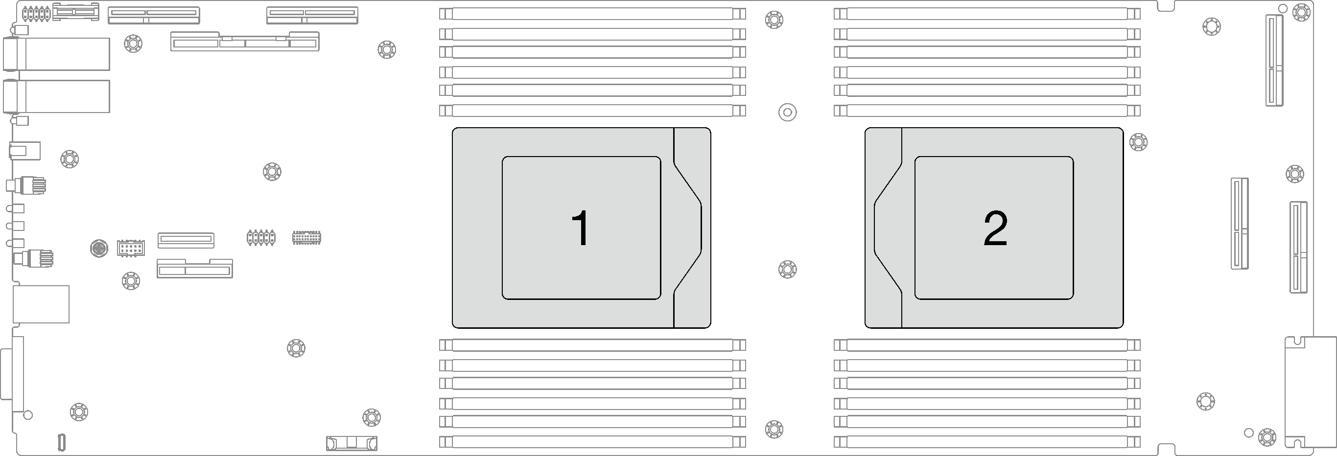
See Lenovo ServerProven website for a list of processors supported for your system. All processors on the system board must have the same speed, number of cores, and frequency.
Optional devices available for your system might have specific processor requirements. See the documentation that comes with the optional device for information.
Go to Drivers and Software download website for ThinkSystem SD665 V3 to see the latest firmware and driver updates for your server.
Go to Update the firmware for more information on firmware updating tools.
Procedure
- Install the processor.
 Slide the processor carrier into the rail frame.AttentionMake sure the processor carrier is well seated inside the rail frame.
 Use index finger of both hands to press down the rail frame.
 Use the index finger of both hands to push the rail frame down until the blue latches lock into place.Figure 2. Install the processor into the rail frame
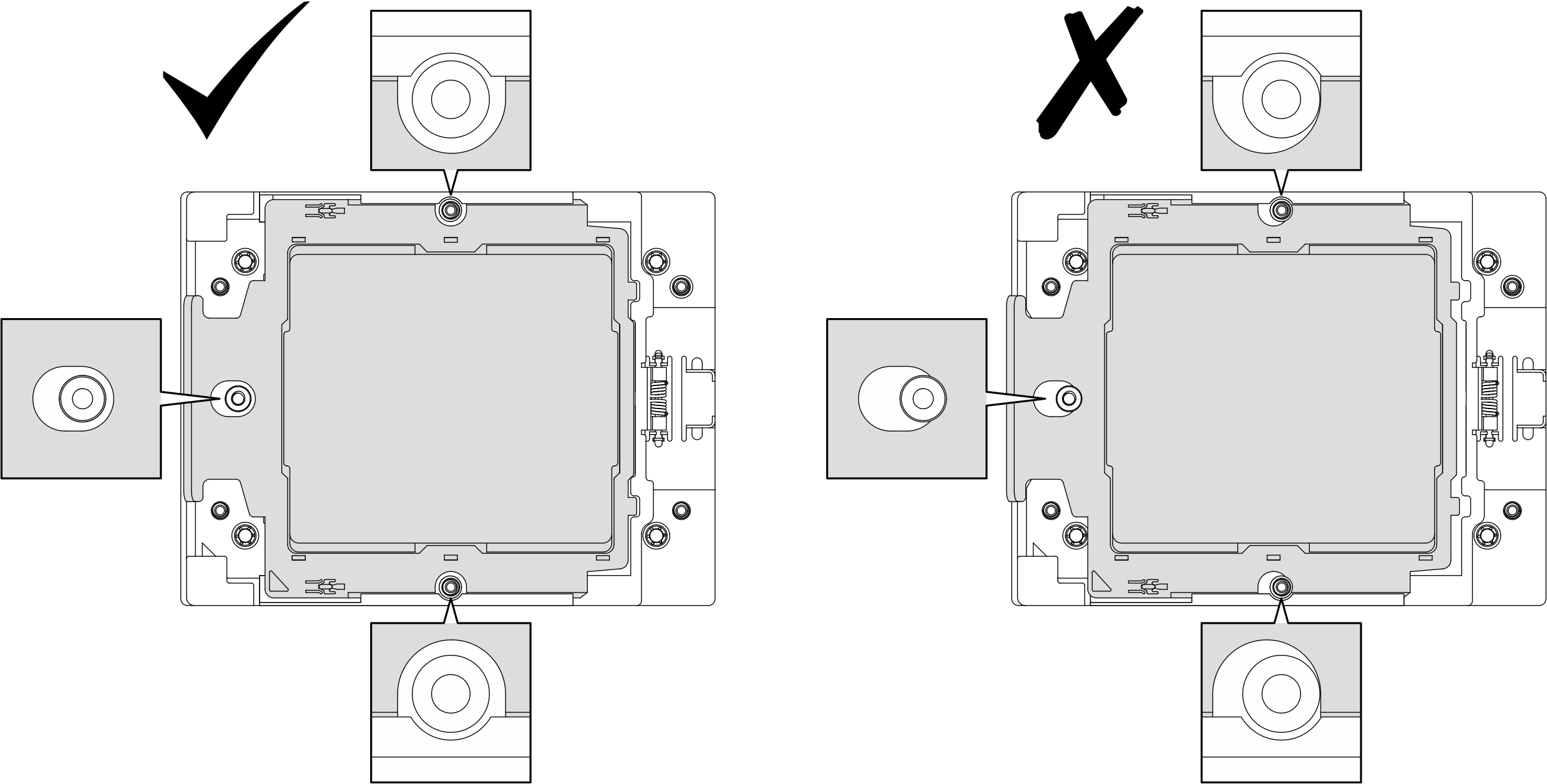
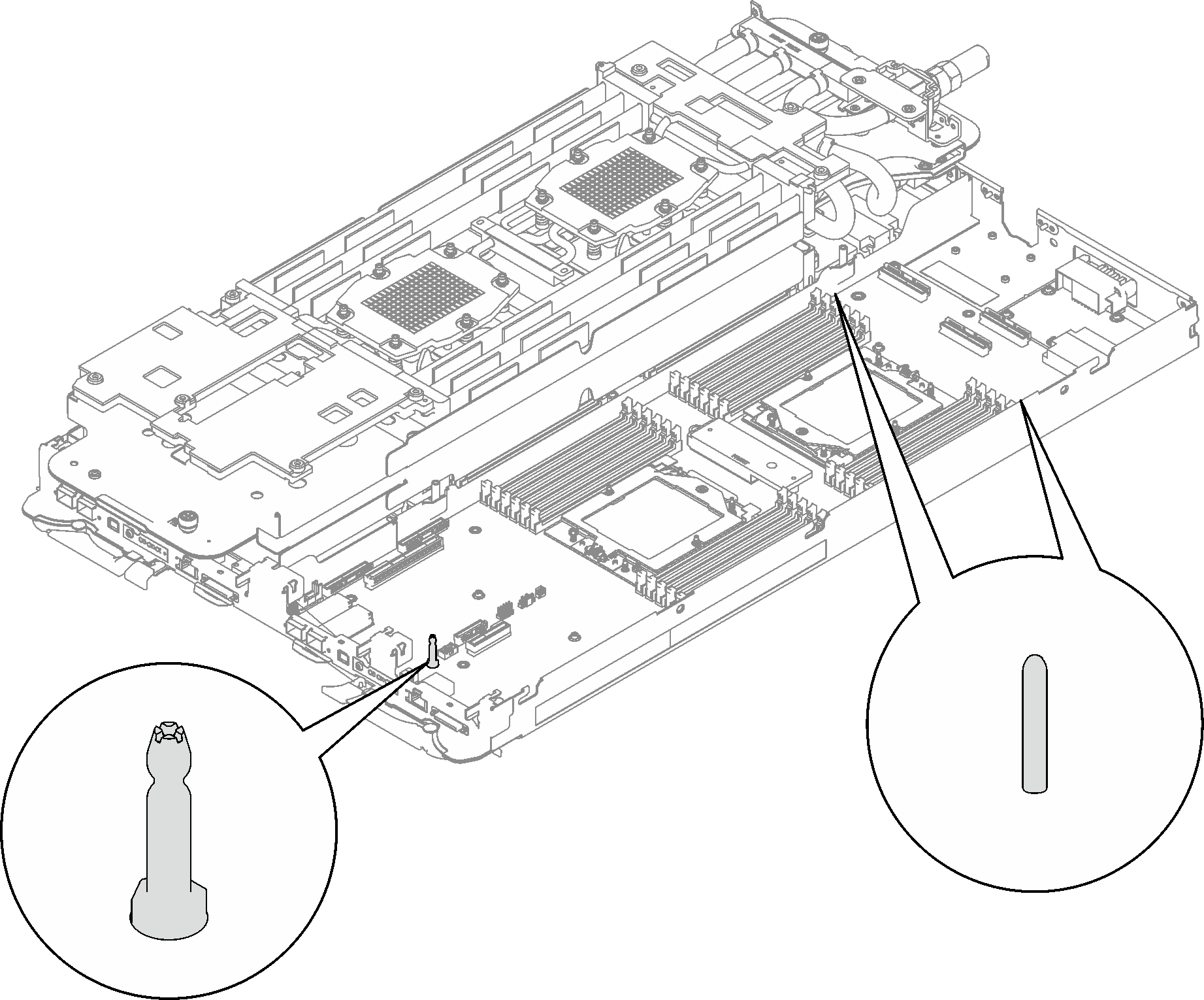
- There are two semicircular cutouts and one oval cutout on the rail frame. Make sure the studs on the processor socket are seated in the center of these three cutouts. If the stud is seated near left side or right side, the stud placement is incorrect. If the stud placement is incorrect, repeat Step 2.1, 2.2, and 2.3 (, , and ) to reinstall the processor carrier to the rail frame until the placement is correct.Figure 3. Processor socket studs placement
 Slightly press the processor carrier to ensure the processor is correctly seated in the socket..AttentionTo avoid processor damage, do not apply excessive force to the processor. Pressing on the processor can be done only when the processor socket studs are in the center of the semicircular cutouts.
 Close the retention frame.
 Use a Torx T20 screwdriver to tighten the screw.Figure 4. Securing the retention frame to the processor socket
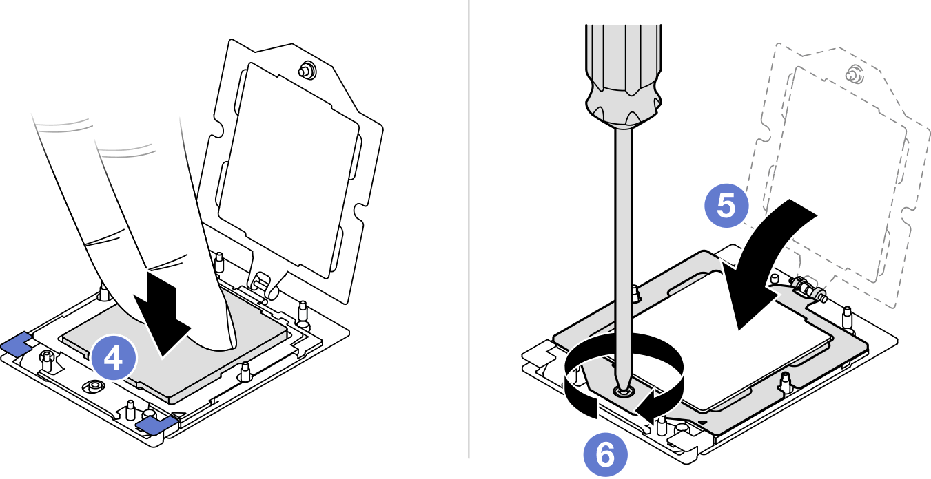
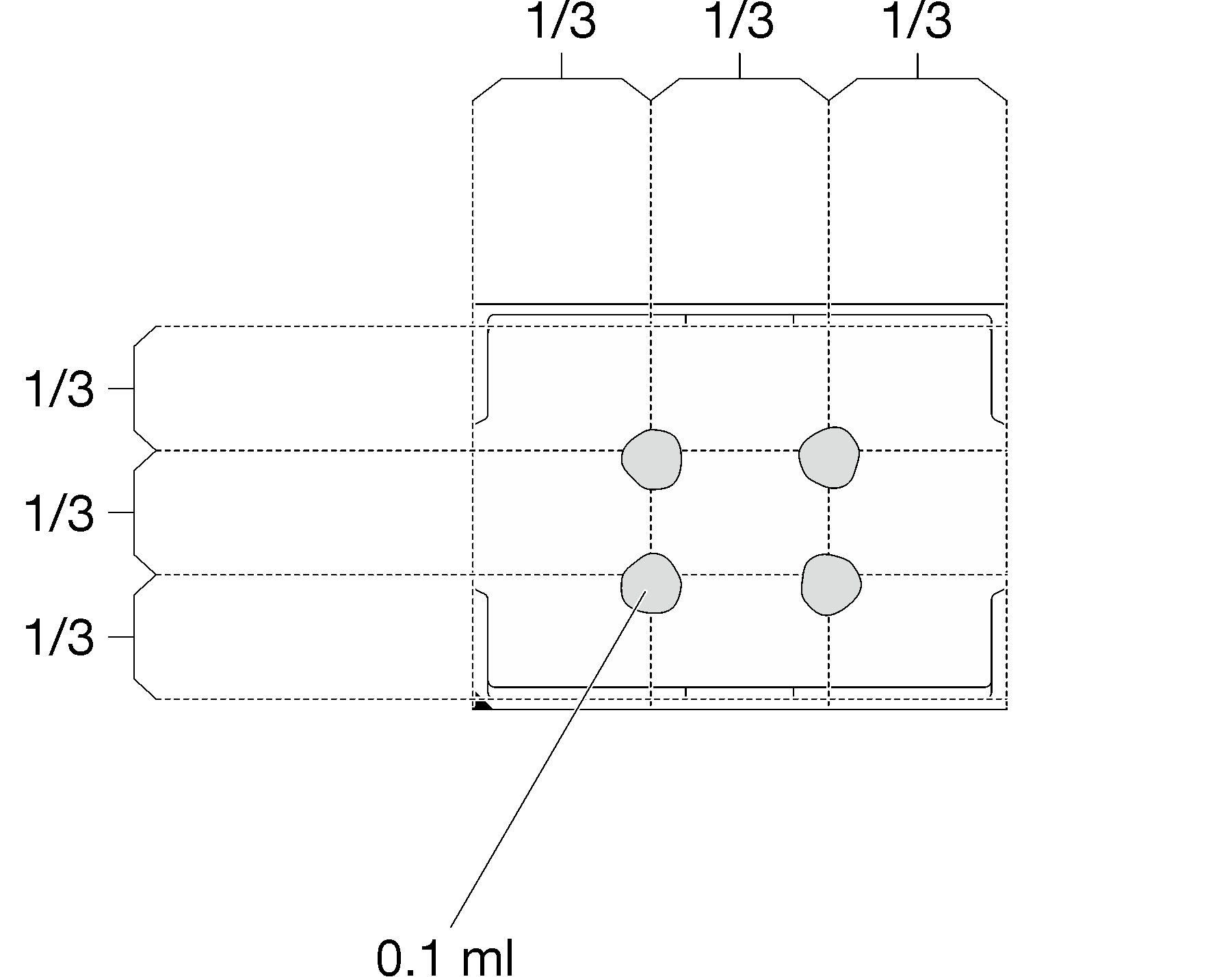
- Apply the thermal grease on the top of the processor with syringe by forming four uniformly spaced dots, while each dot consists of about 0.1 ml of thermal greaseNoteCarefully place the processor and retainer on a flat surface with the processor-contact side down.Figure 5. Thermal grease application
- If needed, remove plastic grease covers from the underside of processor cold plates.Figure 6. Plastic grease covers removal
- Check the gap pads on the bottom side and top side of the water loop, if any of them are damaged, missing, or fallen off, replace them with the new ones. Figure 7. Water loop gap pads (bottom side)
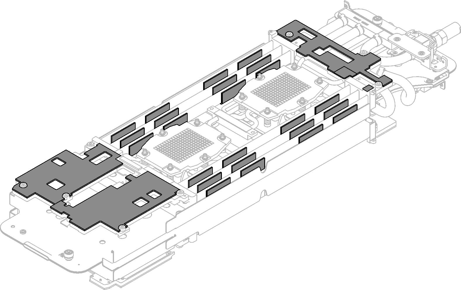 Figure 8. Water loop gap pads (top side)
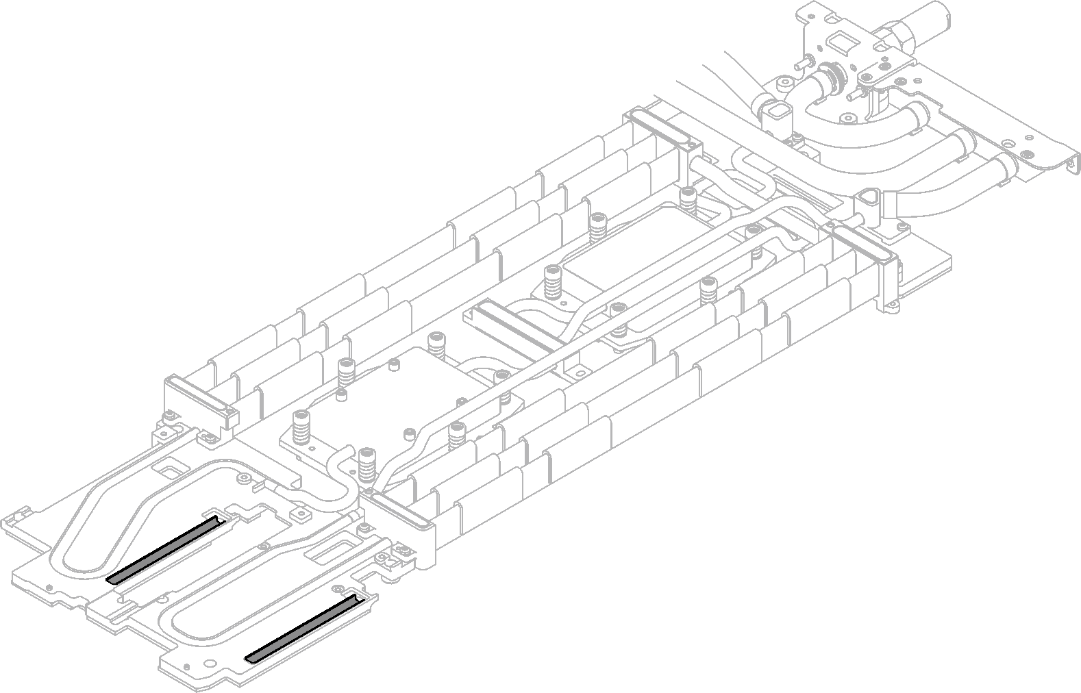
Make sure to follow Gap pad/putty pad replacement guidelines.
- Replace the putty pads on the water loop with new ones.Attention
Putty pad cannot be reused. Whenever a component is removed, putty pads must be replaced with new ones before reinstalling the component.
Figure 9. Water loop putty pads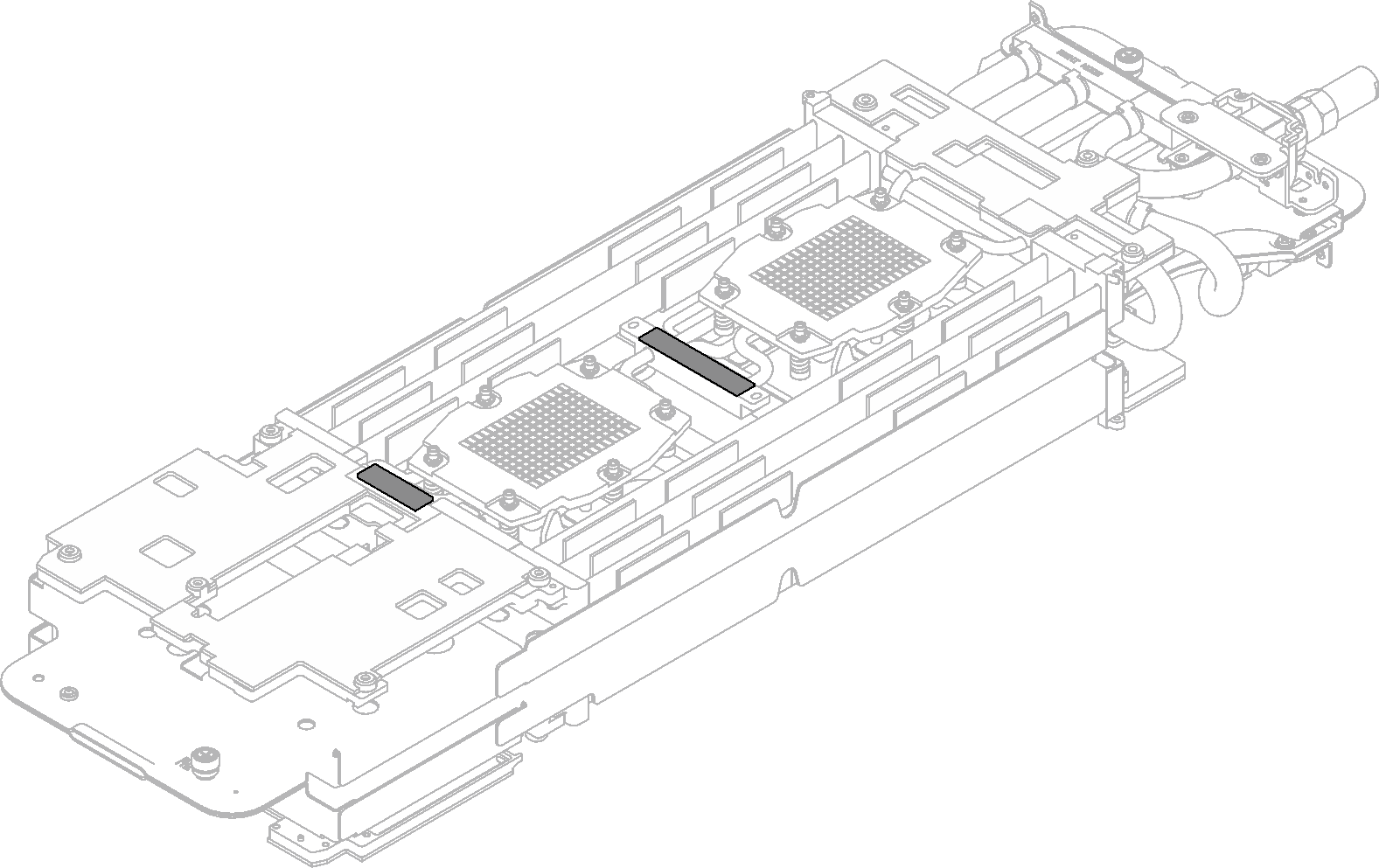
Make sure to follow Gap pad/putty pad replacement guidelines.
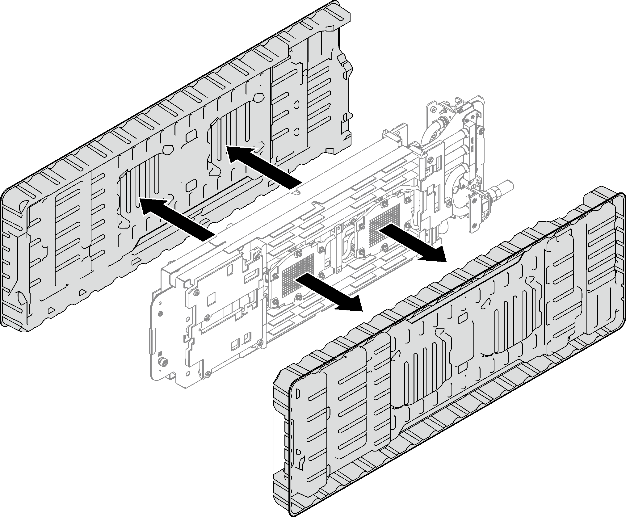
- Carefully rotate the top side of the water loop, position the water loop on the two guide pins near the rear of the node; then, gently put the water loop down and ensure it is firmly seated on the system board.AttentionMake sure to align the water loop with the three guide pins on the right side compute node.Figure 10. Guide pins on the right side compute node
 Attention
Slightly lift the water loop, then rotate it.
Do not tilt the water loop. Keep the water loop horizontal with the tray.
Install the water loop to the tray
Figure 11. Water loop installation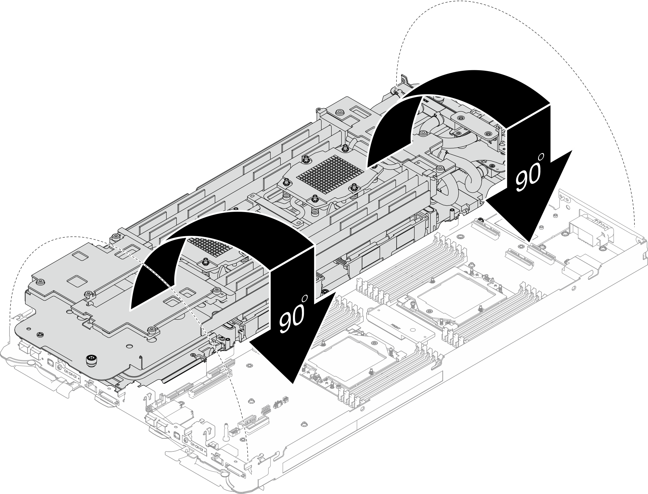
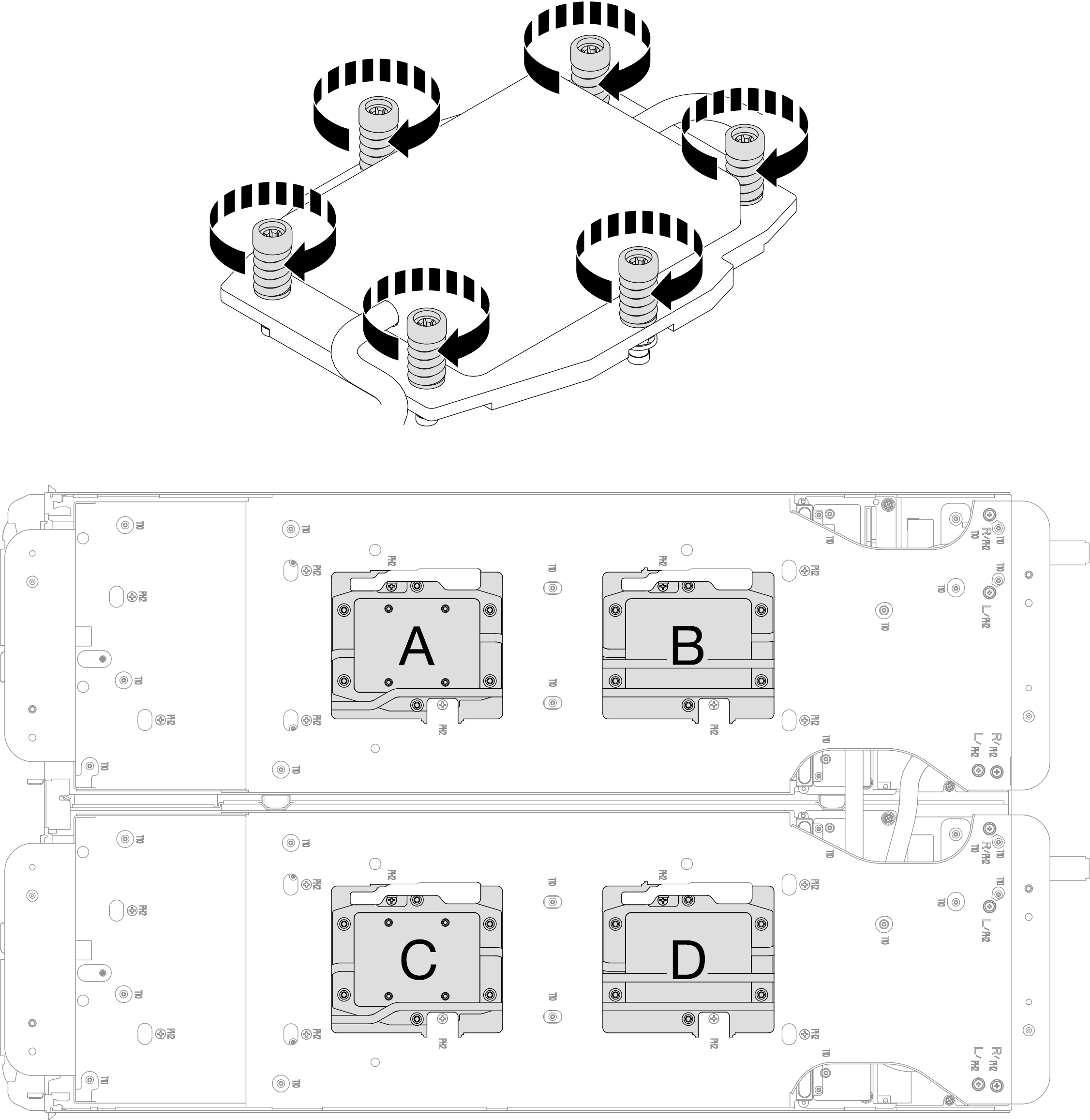
- Install processor cold plate screws (12x Torx T20 screws per node). Follow the screw sequence specified below and tighten the screws with a torque screwdriver. Fully tighten each screw; then, proceed to the next screw.NoteFor reference, the torque required for the screws to be fully tightened/removed is 1.12-1.46 newton-meters, 10-13 inch-poundsFigure 12. Processor cold plate installationFully tighten each screw the order below:
Processor Screw sequence A B C D 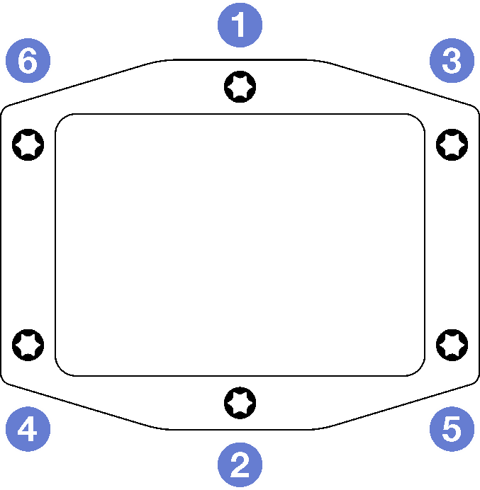
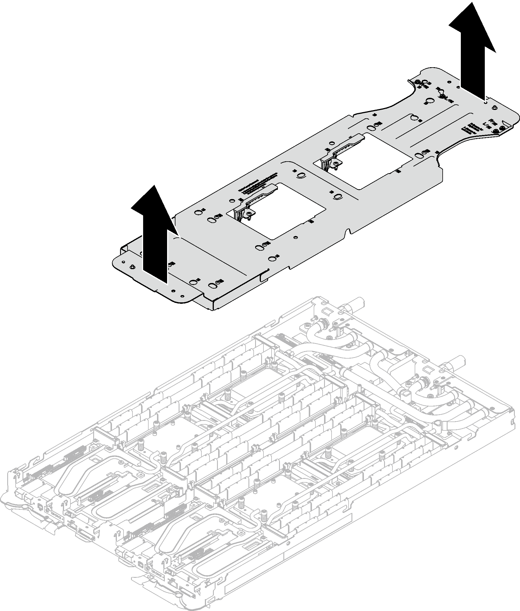
- Loosen water loop carrier screws (12x Phillips #2 screws per node).NoteThe screw holes on the rear of the carrier are marked with
L and R. Select screw holes marked as L when the carrier is on the left node, and R for the right node. Figure 13. Loosening water loop carrier screws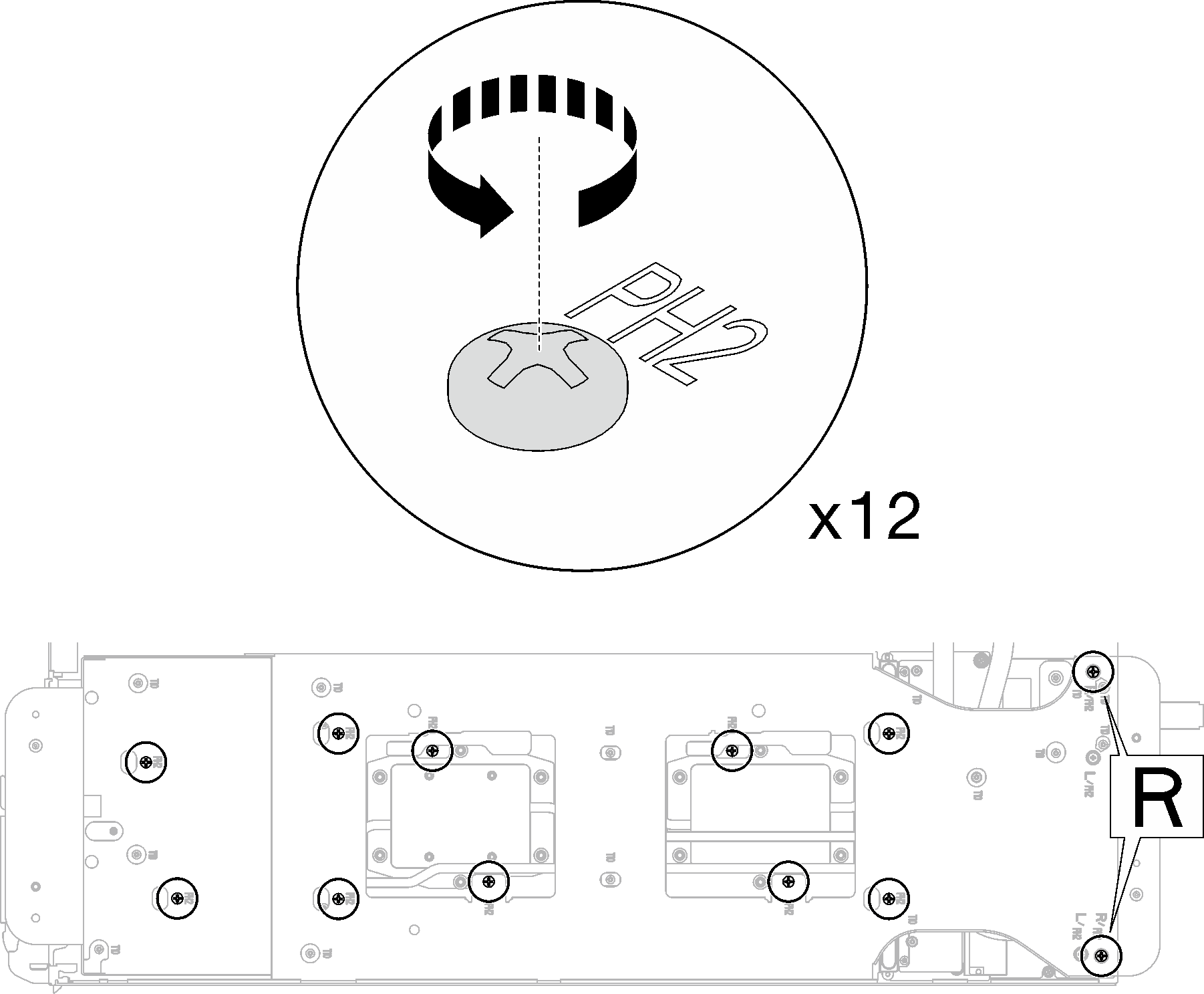
- Carefully lift the water loop carrier up and away from the water loop.Figure 14. Water loop carrier removal
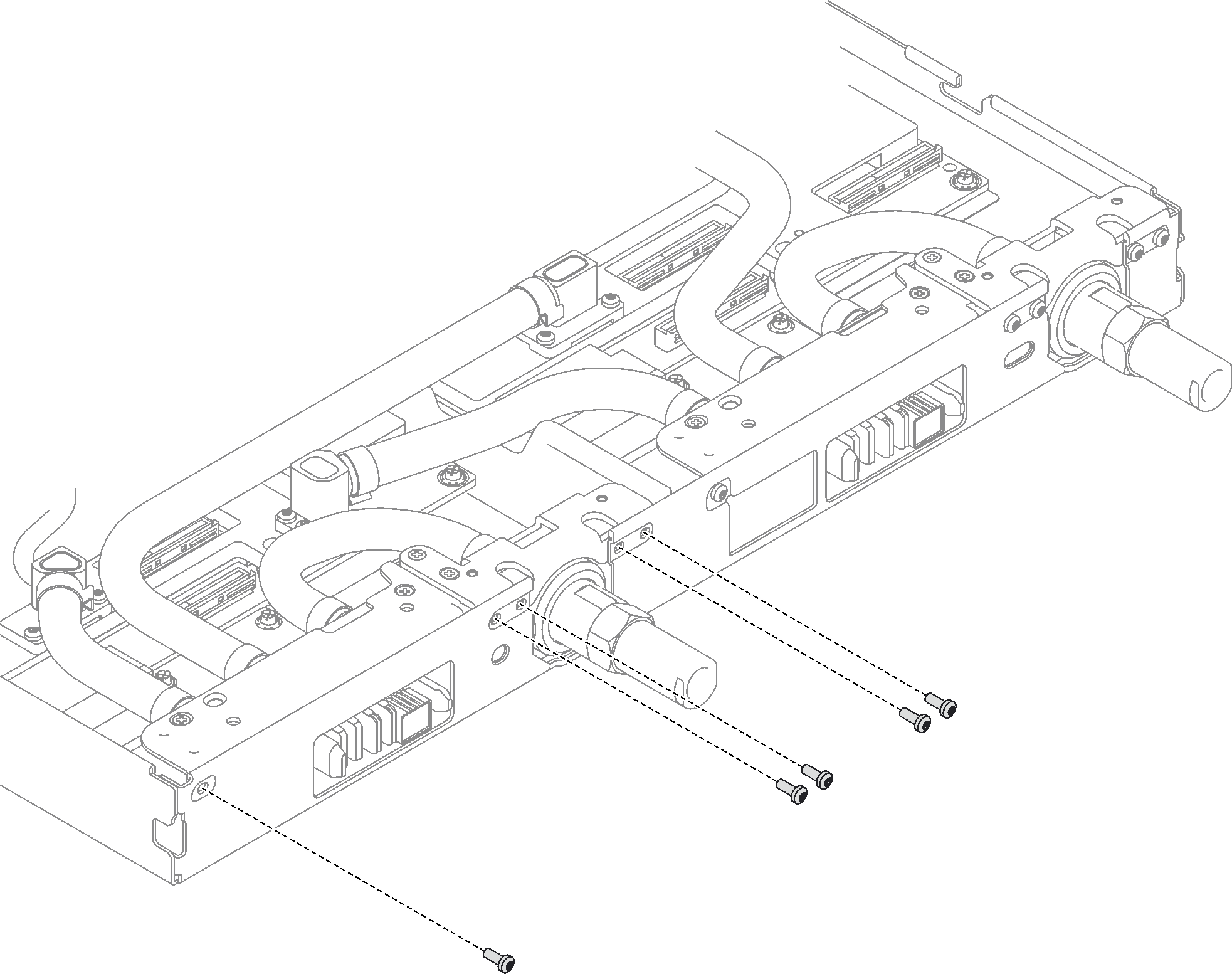
- Install water loop screws and quick connect screws (14x Torx T10 screws per node) with a torque screwdriver set to the proper torque.Note
For reference, the torque required for the screws to be fully tightened/removed is 5.0+/- 0.5 lbf-in, 0.55+/- 0.05 N-M.
Install the 1 VR cold plate screws (x2) with washers.
Installing a new water loop:
Use the washers previously removed from the defect water loop. If there were no washers on the VR cold plate originally, use the washers in VR Conduction Plate 12.4 (including washers).
Reinstalling the water loop:
You may not be installing a new water loop, but is reinstalling the water loop after replacing the system board, processor, or power distribution board. In this case, use the washers previously removed from the water loop. If there were no washers on the VR cold plate originally, it is not required to install VR cold plate with washers.
Figure 15. VR cold plate screws with washers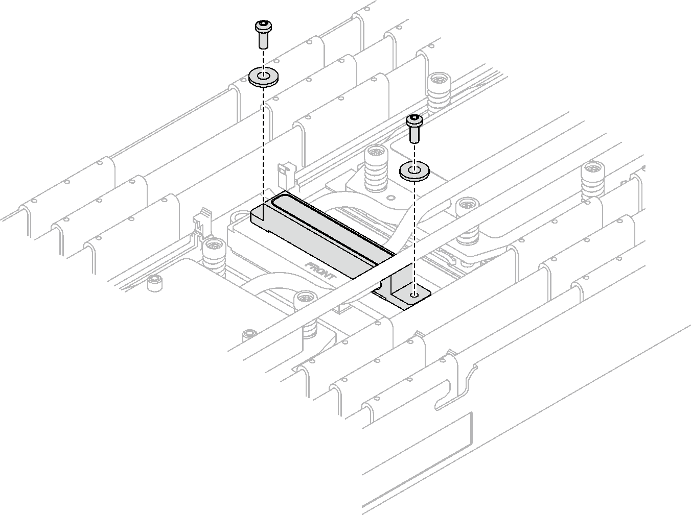 Figure 16. Water loop screws and quick connect screws installation
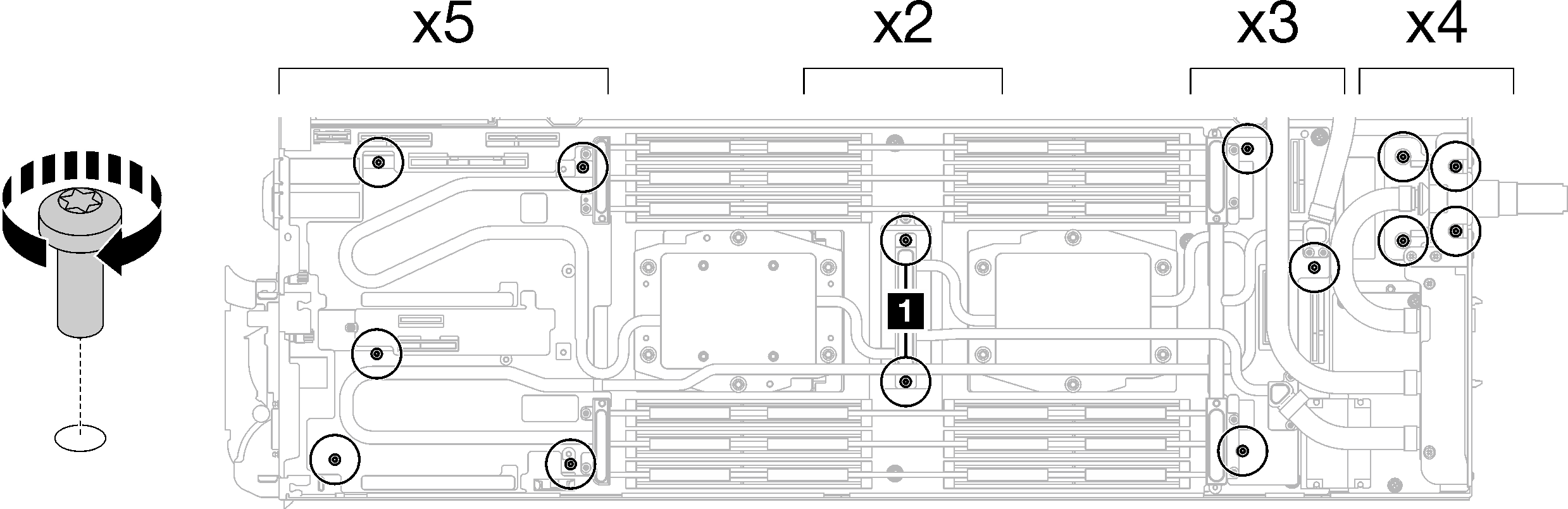
- Install the five Torx T10 screws to secure the quick connect.Figure 17. Quick connect screw installation
Install the memory modules. See Install a memory module.
Install the DIMM comb. See Install a DIMM comb.
Install the M.2 backplane assembly. See Install the M.2 backplane assembly.
Install the drive cage. See Install a drive cage assembly.
Install the PCIe riser assembly. See Install a PCIe riser assembly (ConnectX-6) , Install a PCIe riser assembly (ConnectX-7 NDR 200), or Install a PCIe riser assembly (ConnectX-7 NDR 400).
Install the cross braces. See Install the cross braces.
Install the tray cover. See Install the tray cover.
Install the tray into the enclosure. See Install a DWC tray in the enclosure.
- Connect all required external cables to the solution.NoteUse extra force to connect QSFP cables to the solution.
Check the power LED on each node to make sure it changes from fast blink to slow blink to indicate all nodes are ready to be powered on.
Demo video