Install the system board
Follow instructions in this section to install the system board.
About this task
Required tools
Make sure you have the required tools listed below in hand to properly replace the component.- Prepare the following screwdrivers:
- Phillips #1 head screwdriver
- Phillips #2 head screwdriver
Removing and installing this component requires trained technicians. Do not attempt to remove or install it without proper training.
Read Installation Guidelines and Safety inspection checklist to ensure that you work safely.
Touch the static-protective package that contains the drive to any unpainted metal surface on the server; then, remove the drive from the package and place it on a static-protective surface.
Go to Drivers and Software download website for ThinkEdge SE100 to see the latest firmware and driver updates for your server.
Go to Update the firmware for more information on firmware updating tools.
Procedure
- Make preparation for this task.
- Check the thermal pads on node covers. If a thermal pad is in any of the following conditions, replace the thermal pad with a new one. See Thermal pad installation guidelines to identify the required thermal pad kit and follow the thermal pad instructions.
- The thermal pad is damaged or detached from the surface.
- The new part to be installed is of different brand or form factor from the replaced one; the new part might cause thermal pads to be deformed or damaged.
Figure 1. Top cover thermal pads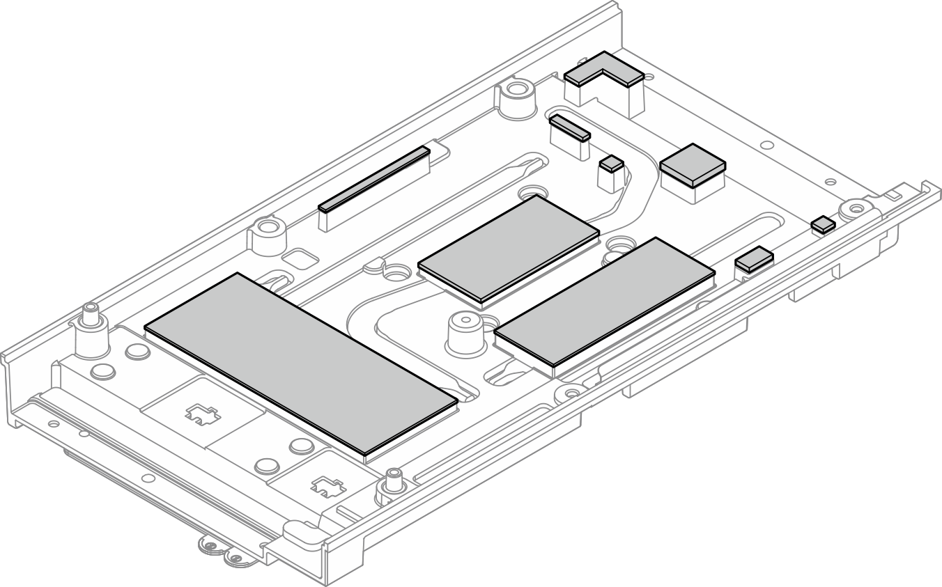 Figure 2. Bottom cover thermal pads
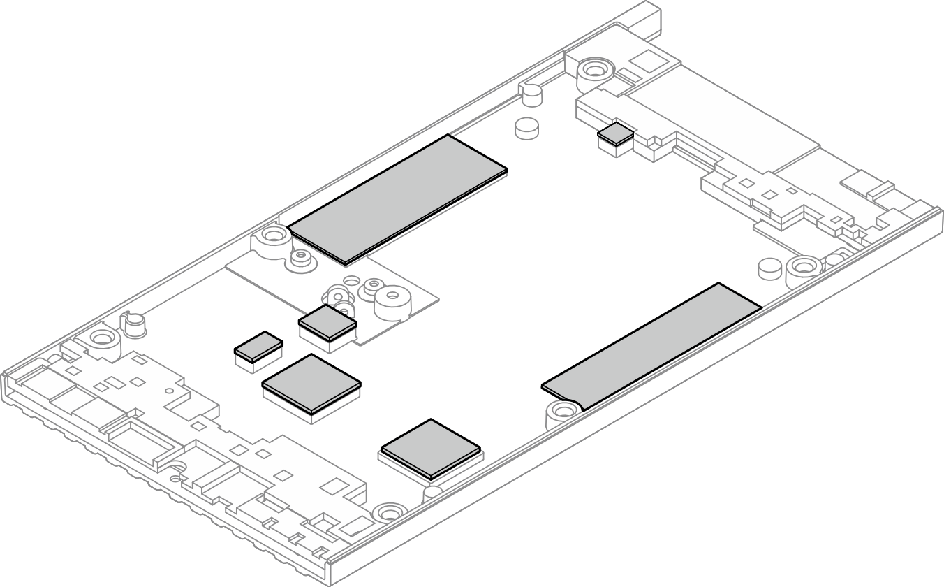
- Check the thermal pads on node covers. If a thermal pad is in any of the following conditions, replace the thermal pad with a new one. See Thermal pad installation guidelines to identify the required thermal pad kit and follow the thermal pad instructions.
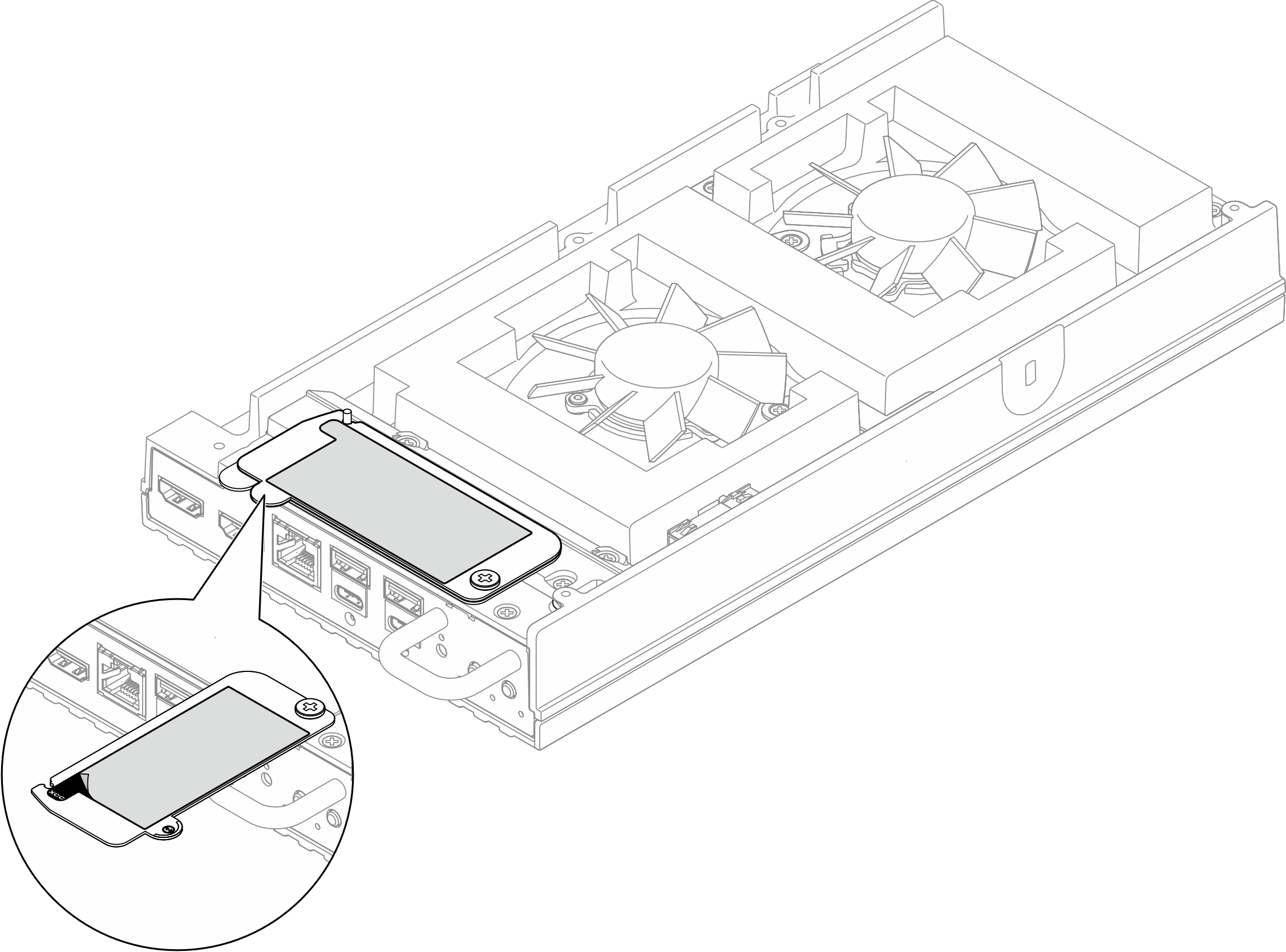
- Peel away the XClarity Controller network access label on the processer heat sink of the system board and attach it to the pull-out information tab on the top cover.Figure 3. Lenovo XClarity Controller network access label on the pull-out information tab
- Place the system board on the static-protective clean surface with the top side facing up, and then install the following components to the system board:
- If an insulating pull tab is under the CMOS battery on the system board, remove it.Figure 4. Removing the insulating pull tab

- If an insulating pull tab is under the CMOS battery on the system board, remove it.
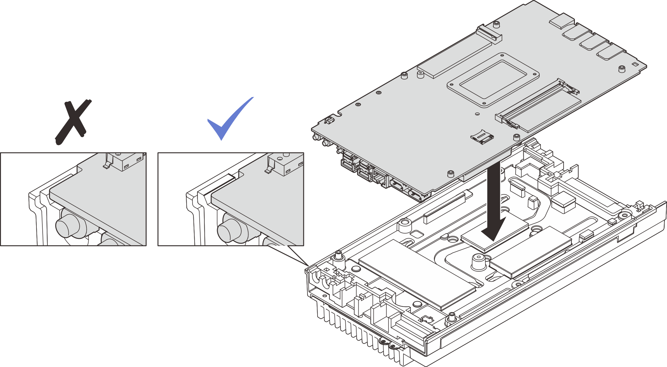
- Hold the system board by its edge, and carefully turn the system board over and place the bottom side of the system board facing up; then lower the system board onto the top cover.NoteMake sure not to let the system board touch the rubber on the edge of the top cover when installing the system board.Figure 5. Installing the system board
- Install the bottom cover.
 Align the bottom cover with the guiding slots on both sides of the node; then, lower the bottom cover onto the node.
 Insert the front and rear I/O brackets into the node until they are seated in place.Figure 6. Installing the bottom cover
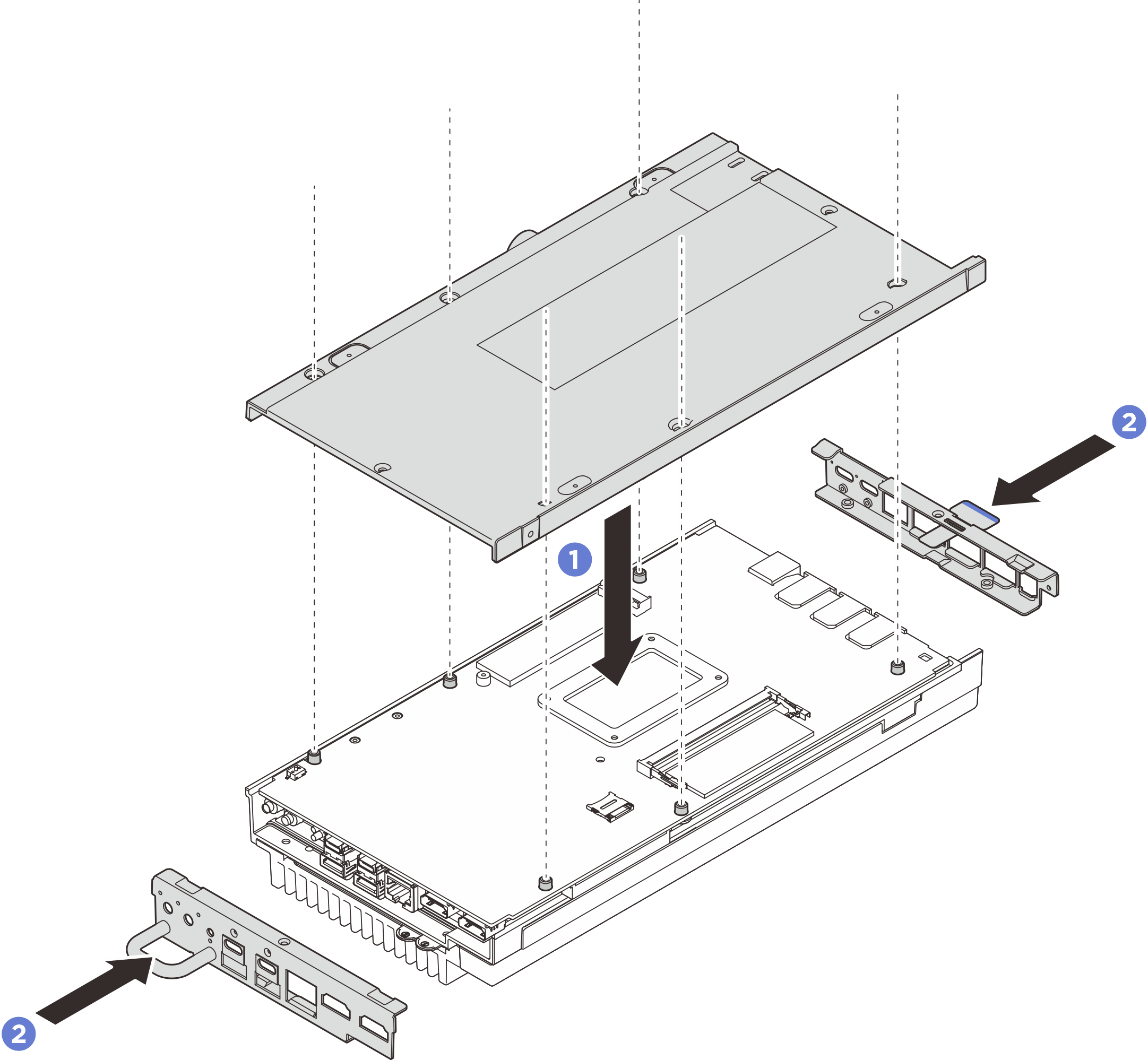
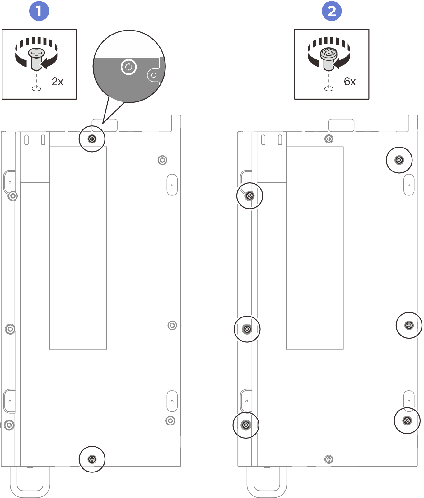
- Tighten screws to the bottom cover.
- Tighten two Phillips #1 screws to the short sides of the bottom cover.Note
The Phillips #1 screws are with pre-appliced white threadlocking adhesive, and the corresponding screw holes are circled by white color. Make sure to fasten the screws to the corresponding holes.
- Tighten six Phillips #2 screws to the long sides of the bottom cover as illustrated; then reverse the node and place the top side facing up.Figure 7. Installing the screws
- Tighten screws to secure the cover.
- Tighten four Phillips #2 screws to the long sides of the top cover.NoteThe screw holes might be covered by fan cables. Carefully pull the fan cable out a little bit to install the screw, and put the cable back after installing the screw.
- Slide the pull-out information tabs outward from the node.
 Tighten the four Phillips #1 screws to the short sides of the top cover; then place the bottom side of the node facing up.Note
The Phillips #1 screws are with pre-appliced white threadlocking adhesive, and the corresponding screw holes are circled by white color. Make sure to fasten the screws to the corresponding holes.
Make sure to slide the pull-out information tabs back once the screw underneath is fully installed.
Figure 8. Installing the screws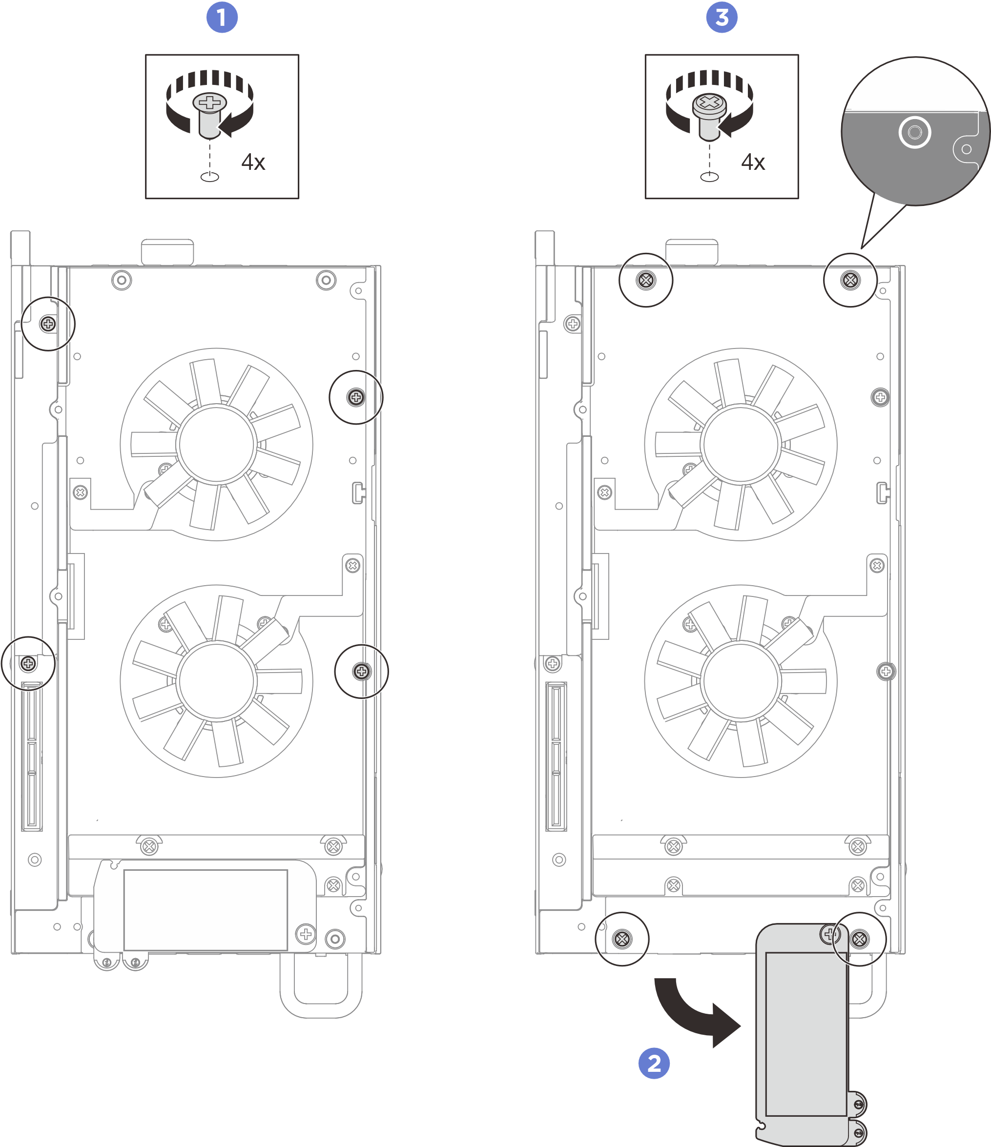
After you finish
Install the expansion kit or the expansion filler. See Install the expansion kit or Install the expansion filler.
Install the fan shroud. See Install the fan shroud.
Ensure that all components have been reassembled correctly and that no tools or loose screws are left inside your server.
If necessary, reinstall the node to the enclosure or mount. See Configuration guide.
Reconnect the power cords and any cables that you removed.
Power on the server and any peripheral devices. See Power on the server.
Reset the system date and time.
- Update the machine type and serial number with new vital product data (VPD). Use the Lenovo XClarity Provisioning Manager to update the machine type and serial number. See Update the Vital Product Data (VPD).Note
- If the node is installed in a ThinkEdge SE100 1U2N Enclosure or a ThinkEdge SE100 1U3N Enclosure, change the machine type for proper operation. See Change the machine type for operating in an enclosure (trained technician only).
- Machine type number and serial number can be found on the ID label, see Identify the server and access the Lenovo XClarity Controller.
Update the UEFI, XCC and LXPM firmware to the specific version supported by the server. See Update the firmware.
If applicable, install Lenovo Features on Demand activation key. See the
License Management
section in the XCC documentation compatible with the server at Lenovo XClarity Controller portal page.Update the public key. See the
Update Device Key
section of ThinkShield Edge Mobile Management Application User Guide or ThinkShield Key Vault Portal Web Application User Guide in ThinkEdge Security for more details.Note- The role of Lenovo ID should be Maintenance User to update the public key in ThinkShield Key Vault Portal web interface or ThinkShield mobile app.
- (Lenovo service technician only) See How to update public key after system board replacement for the details.
If hiding TPM is needed, see Hide/observe TPM.
Set the TPM policy. See Set the TPM policy.
Optionally, enable UEFI Secure Boot. See Enable UEFI Secure Boot.
Reconfigure the following ThinkEdge security features if necessary.
Change System Lockdown Mode Control status to ThinkShield Portal. See Activate or unlock the system.
Enable SED encryption. See Manage the Self Encryption Drive Authentication Key (SED AK).
Recover SED AK. See Manage the Self Encryption Drive Authentication Key (SED AK).
Enable security features. See System Lockdown Mode.
Change the emergency XCC password reset settings. See Emergency XCC Password Reset.
Demo video