Install the server to the rack (E3.S bay chassis)
Follow the instructions in this section to install the server to the rack.
About this task
S037  CAUTION The weight of this part or unit is more than 55 kg (121.2 lb). It takes specially trained persons, a lifting device, or both to safely lift this part or unit. |
 CAUTION Use safe practices when lifting. |  CAUTION Drop hazard. |
 CAUTION Do not place any object on top of a rack-mounted device unless that rack-mounted device is intended for use as a shelf. |
Read Installation Guidelines and Safety inspection checklist to ensure that you work safely.
Power off the server and peripheral devices and disconnect the power cords and all external cables. See Power off the server.
Prevent exposure to static electricity, which might lead to system halt and loss of data, by keeping static-sensitive components in their static-protective packages until installation, and handling these devices with an electrostatic-discharge wrist strap or other grounding system.
Procedure
- Lift the server and place it on a flat and stable surface.
Using a lift device: (recommended)
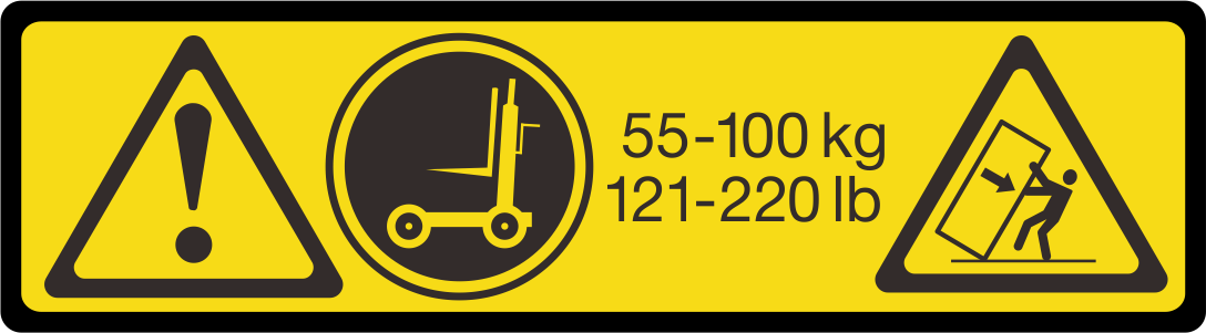 CAUTIONThe weight of this part or unit is more than 55 kg (121.2 lb). It takes specially trained persons, a lifting device, or both to safely lift this part or unit.
Manual lift: (not recommended)
AttentionBefore lifting the server, remove all power supply units and all storage drives.CAUTIONUse safe practices when lifting.CAUTIONDrop hazard.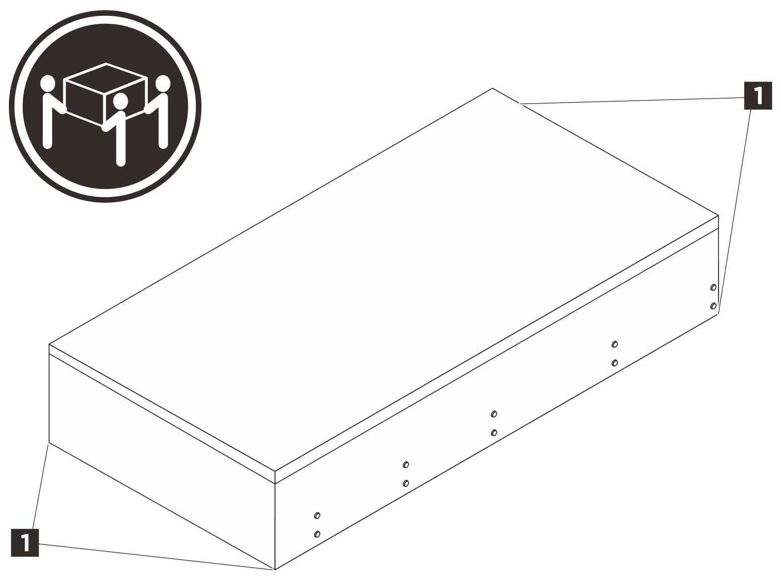 CAUTIONMake sure three people are lifting the server by holding the lift points
1. - Remove the inner rails from the intermediate rails.
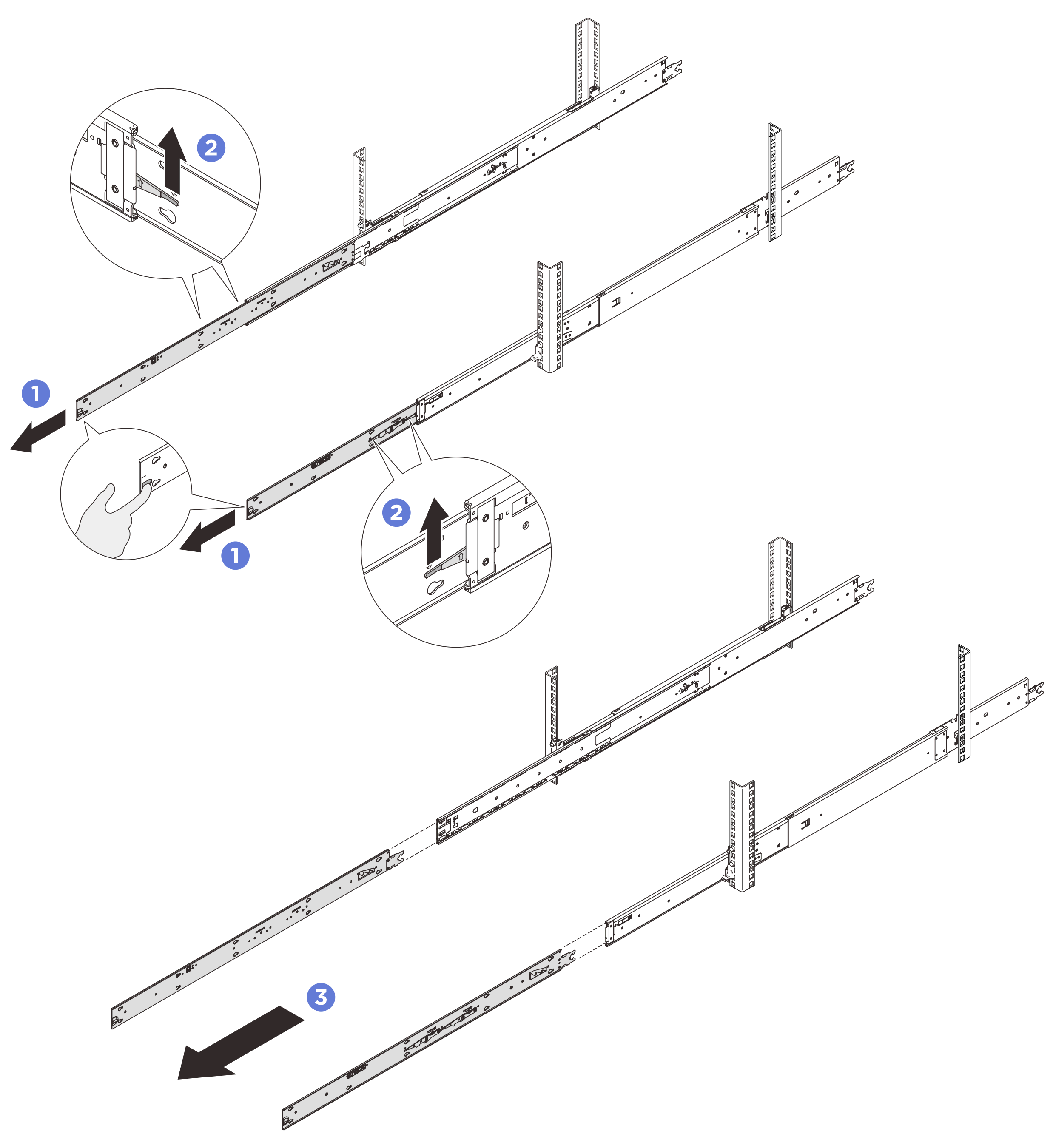
 Pull the inner rails all the way out until they stop.
 Lift the lock latches and pull the inner rails to disengage them from the intermediate rails.
NoteThere are two pairs of lock latches on the rails. Lift both pairs of latches to proceed to slide the inner rails out. Remove the inner rails.
- Align the slots on the inner rail with the corresponding T-pins on the side of the server; then, slide the inner rail forwards until the T-pins lock into place with the inner rail. Make sure all T-pins are engaged with the inner rail. Attention
There are two inner rails, left rail (marked with L) and right rail (marked with R). Ensure that each rail is installed to the corresponding side of the server.
Make sure that the stamp “Front” always faces toward the front when assembling the inner rails to the server.
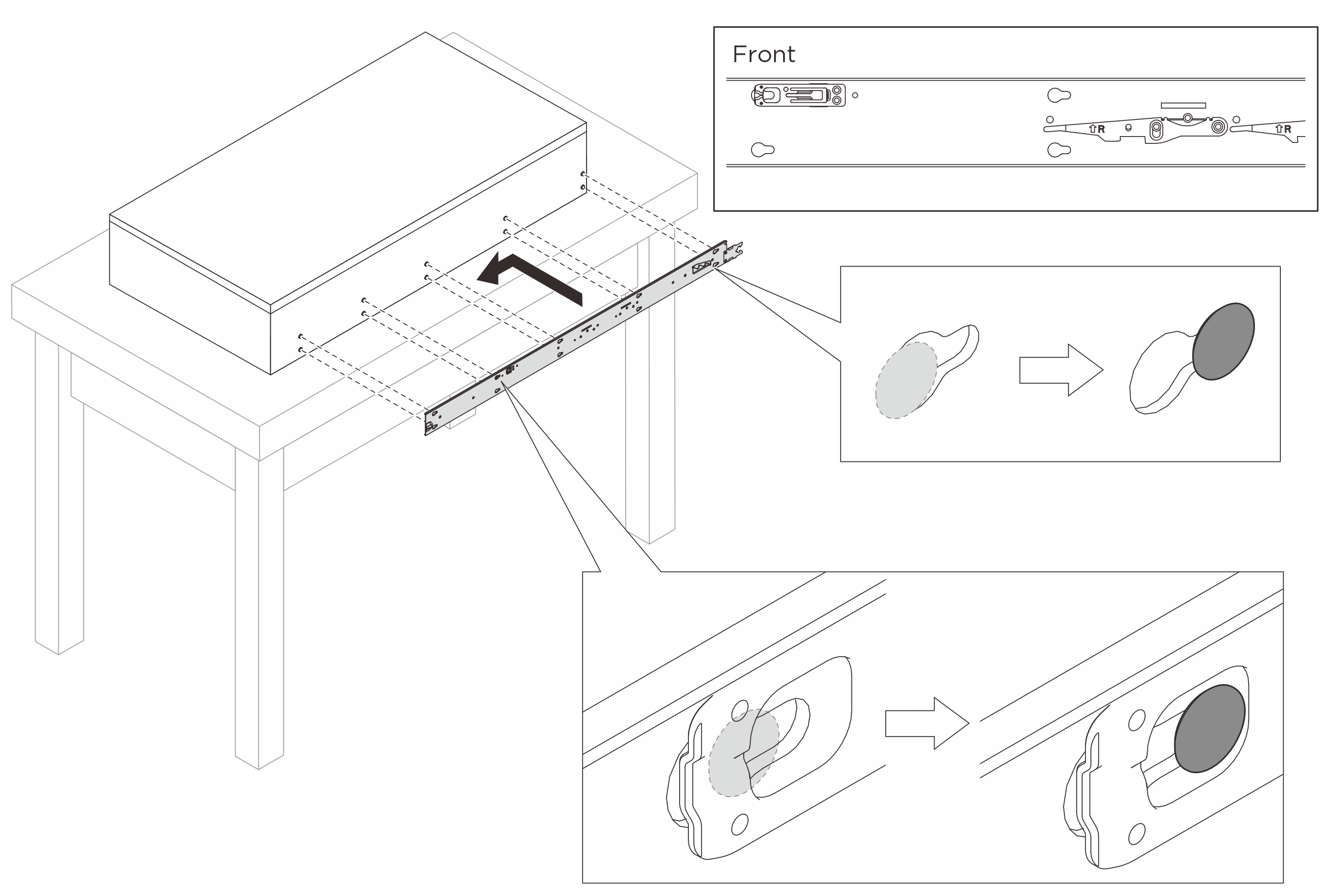
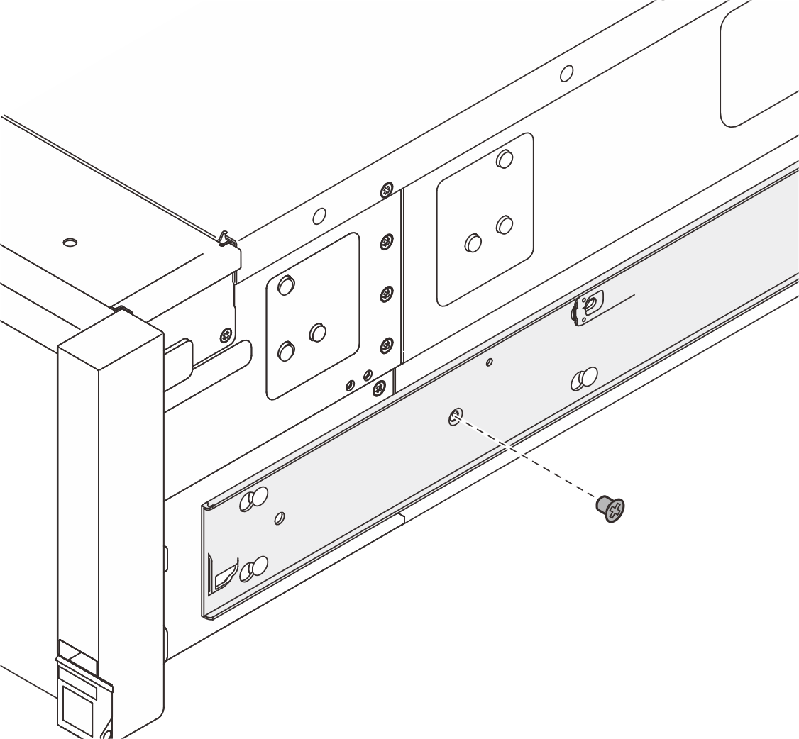
- Insert and tighten an M4 screw to secure the inner rail as shown.
- Attach the lift handles if you need to lift the server manually.
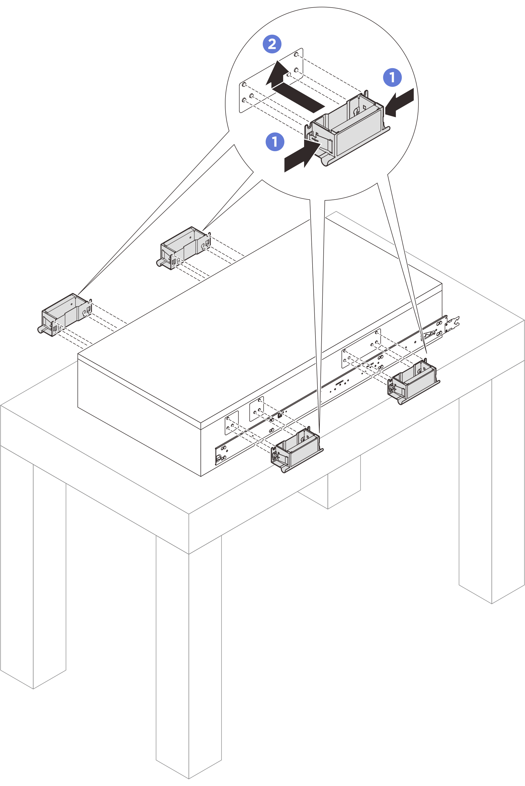
- Pinch both flaps on the side of the handles.
- Align the handles with the 6 posts on the sides of the server; then slide the handles up to secure them to the chassis.
NoteMake sure all 6 posts are secured.
There are 4 lift handles in total. Make sure to install them all properly before lifting the server.
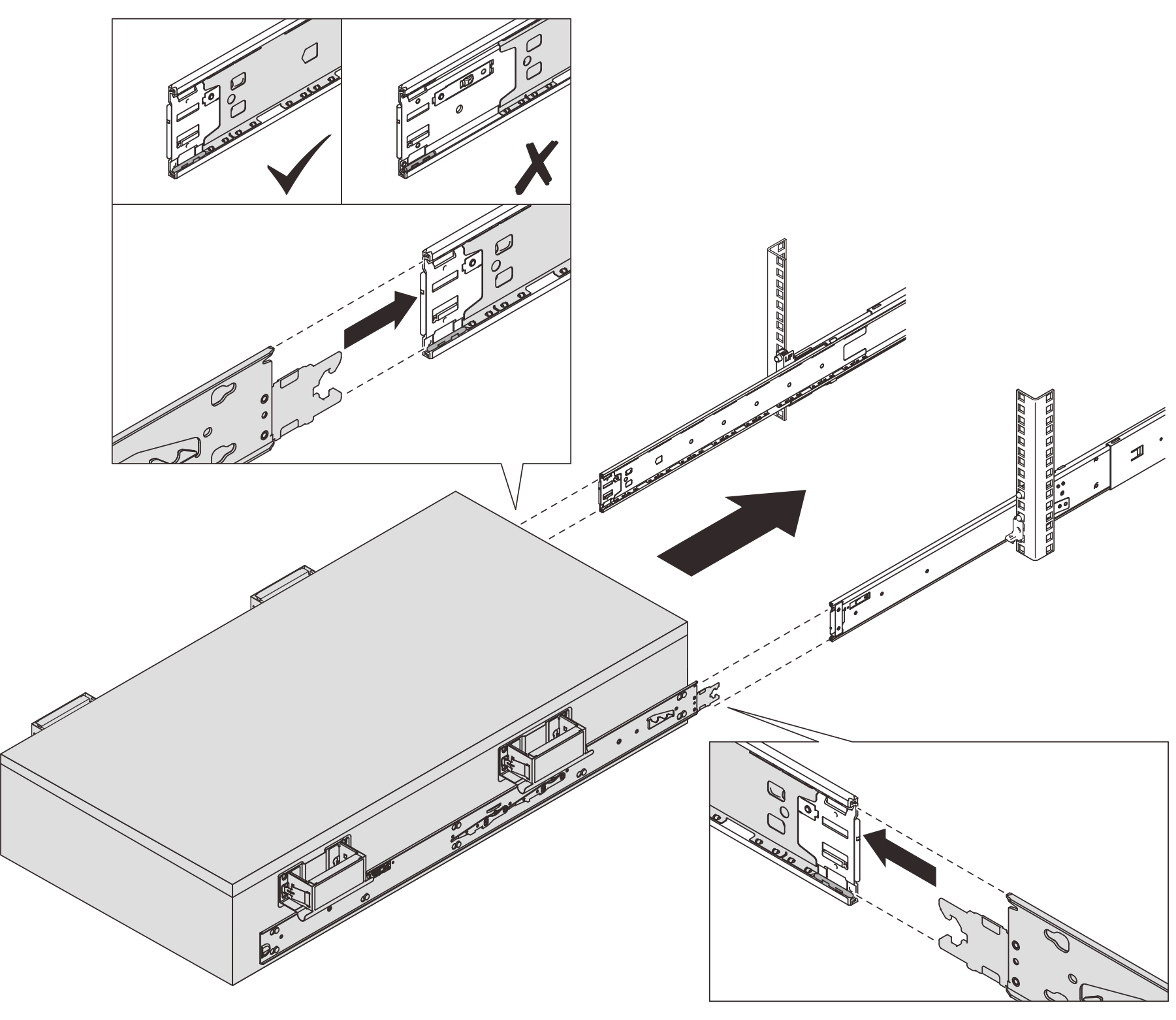
- Install the server to the rack.
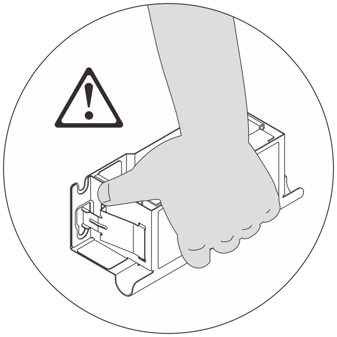
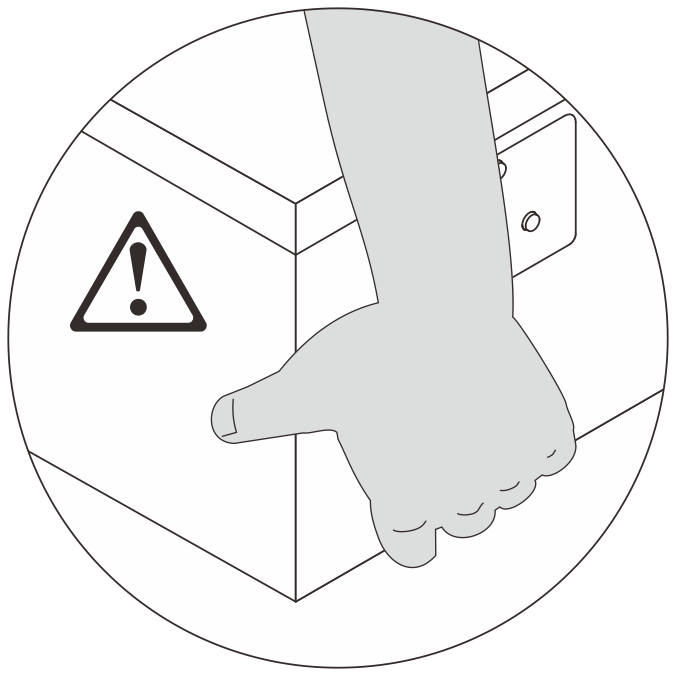 AttentionWhen moving the serve manually, hold the server by its lift points or the lift handles all the time.
- Align both rear ends of the inner rails with the openings in the intermediate rails, and make sure the two pairs of rails mate correctly. Then, carefully slide the server into the rack until the rails stop.AttentionBefore inserting the inner rails into the intermediate rails, make sure that the ball retainers on both sides of the intermediate rails reach the outmost position.
- Remove the front and rear lift handles at both sides if installed.
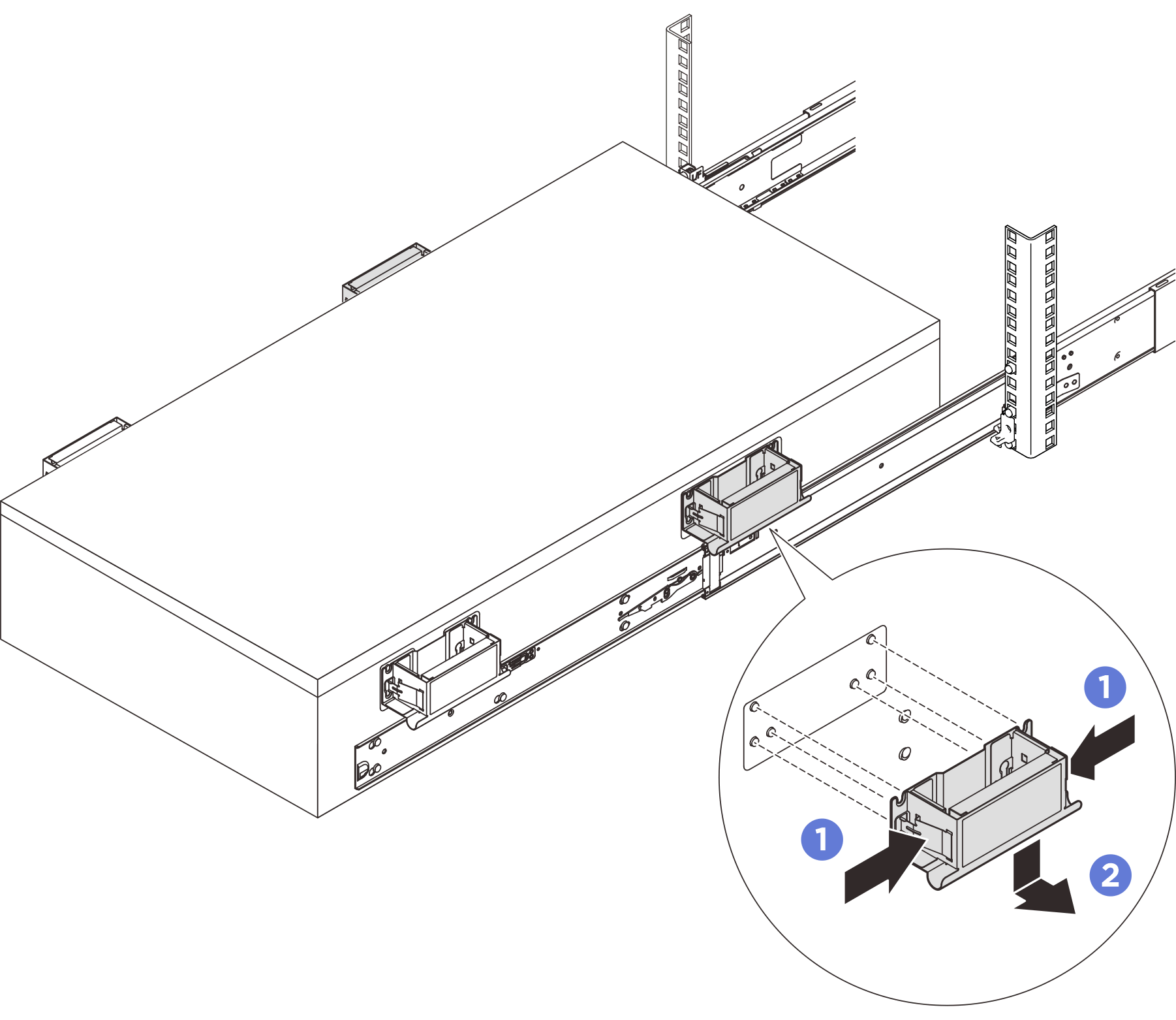
- Pinch both flaps on the side of the handles.
- Slide the handles down to remove them from the server.
NoteMake sure to remove all the lift handles before proceeding sliding in. - Lift the lock latches as shown to slide the server into the rack until it goes into place.
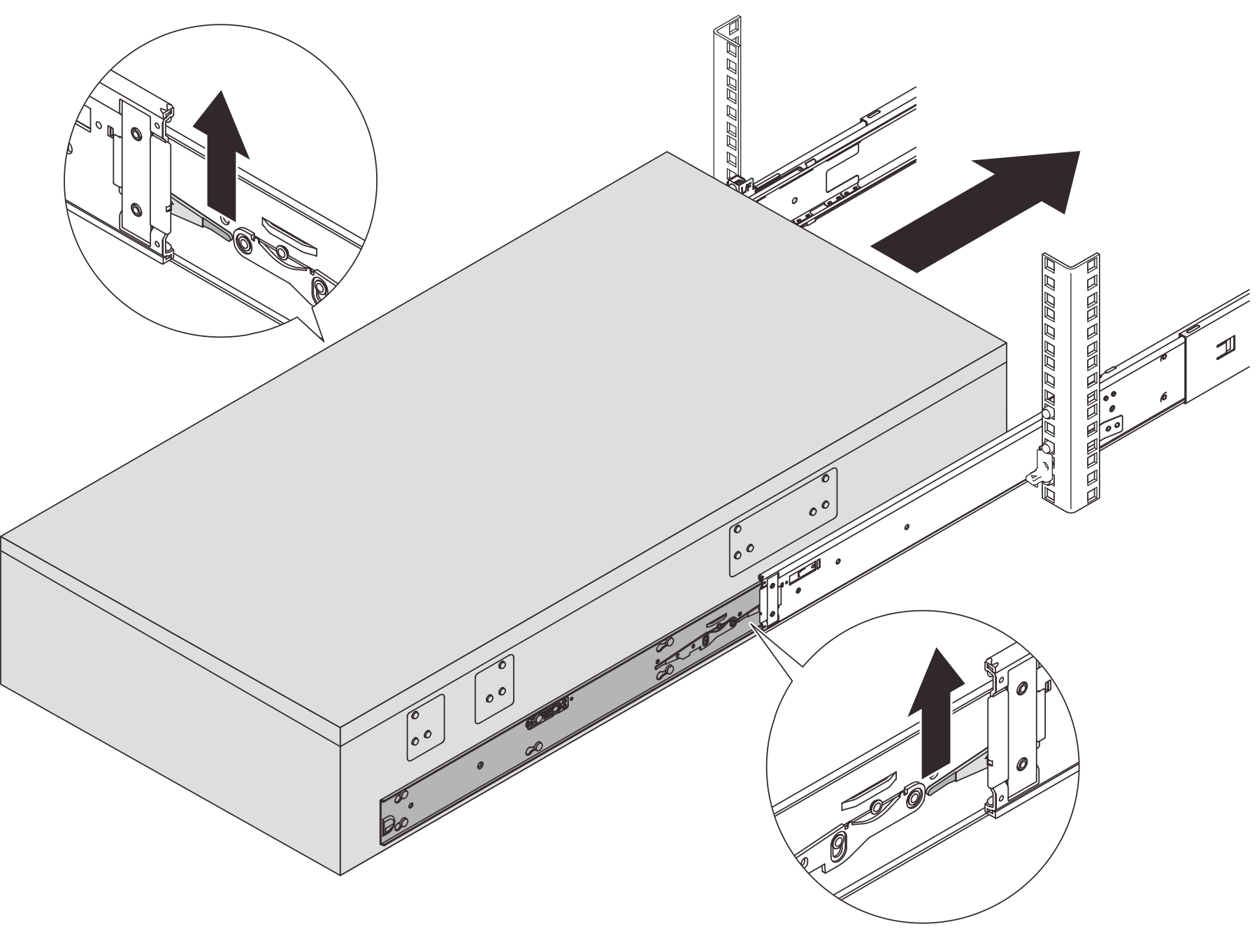 AttentionSlide the server all the way out and all the way back in to make sure the rails are working smoothly.
- Align both rear ends of the inner rails with the openings in the intermediate rails, and make sure the two pairs of rails mate correctly. Then, carefully slide the server into the rack until the rails stop.
- (Optional) Secure the server to the rack.
Rear 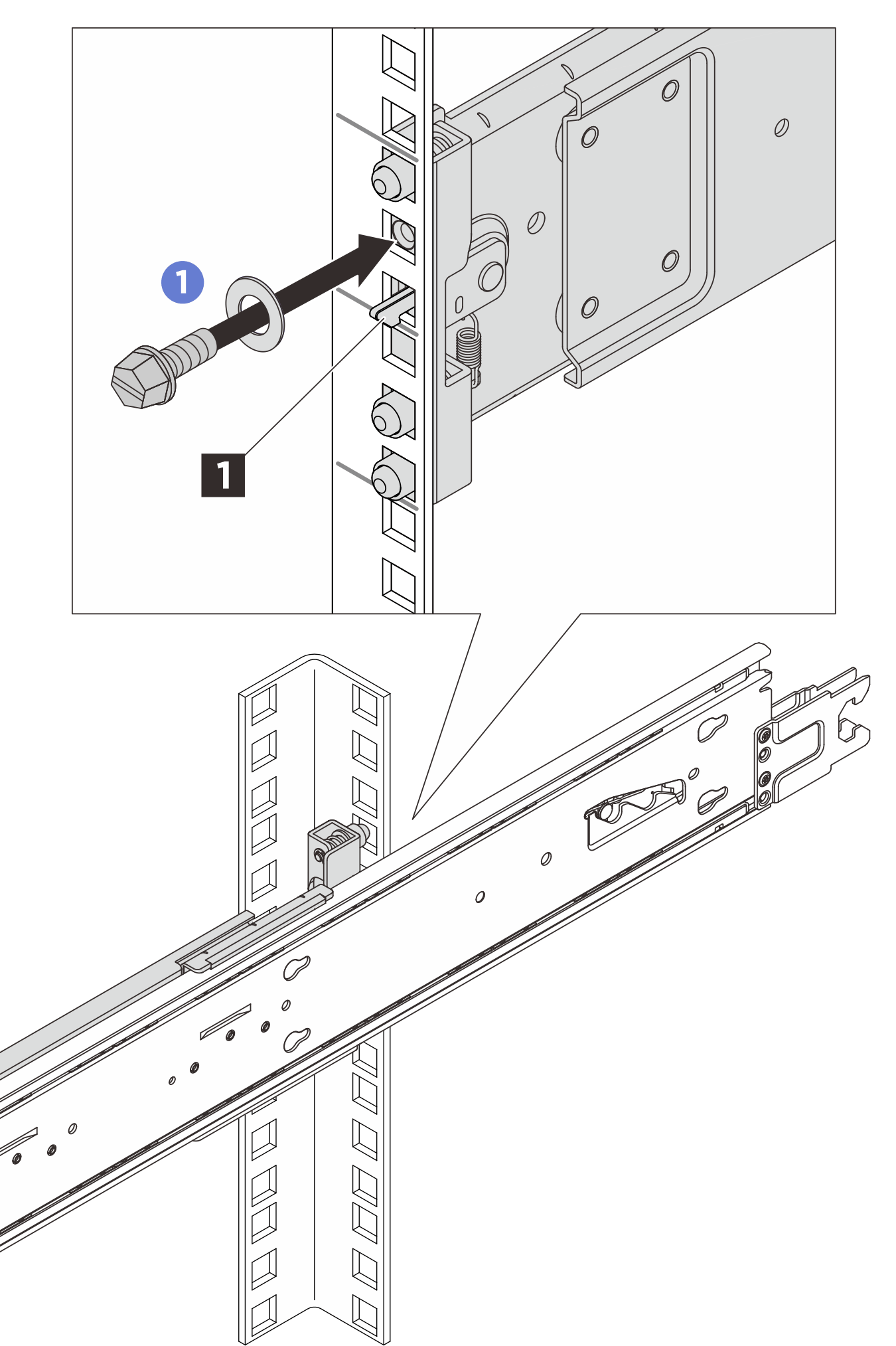
Front 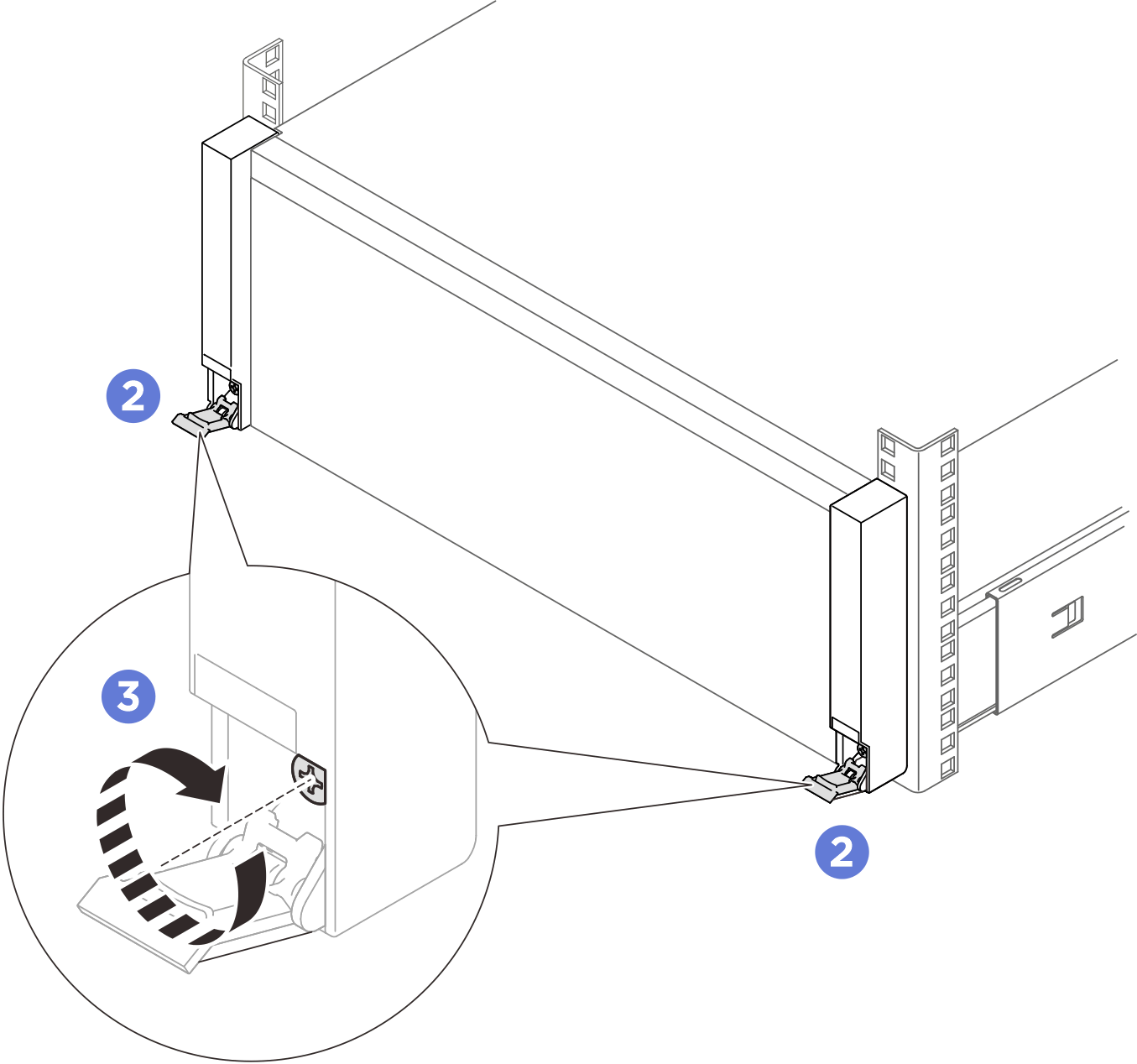 NoteUse either flat-head, hex socket, or Phillips driver for the following instruction.
- Insert and tighten an M5 screw along with a washer to the hole below each hook latch 1.
- Open the rack release latches.
- Tighten the captive screws clockwise with a Phillips screwdriver.
After you finish
Complete the parts replacement. See Complete the parts replacement.