Install the OCP cage
Follow the instructions in this section to install the OCP cage.
About this task
Read Installation Guidelines and Safety inspection checklist to ensure that you work safely.
Power off the server and peripheral devices, disconnect the power cords from the primary chassis, then disconnect the power cords from the secondary chassis. See Power off the server.
Prevent exposure to static electricity, which might lead to system halt and loss of data, by keeping static-sensitive components in their static-protective packages until installation, and handling these devices with an electrostatic-discharge wrist strap or other grounding system.
Go to Drivers and Software download website for ThinkSystem SR950 V3 to see the latest firmware and driver updates for your server.
Go to Update the firmware for more information on firmware updating tools.
Procedure
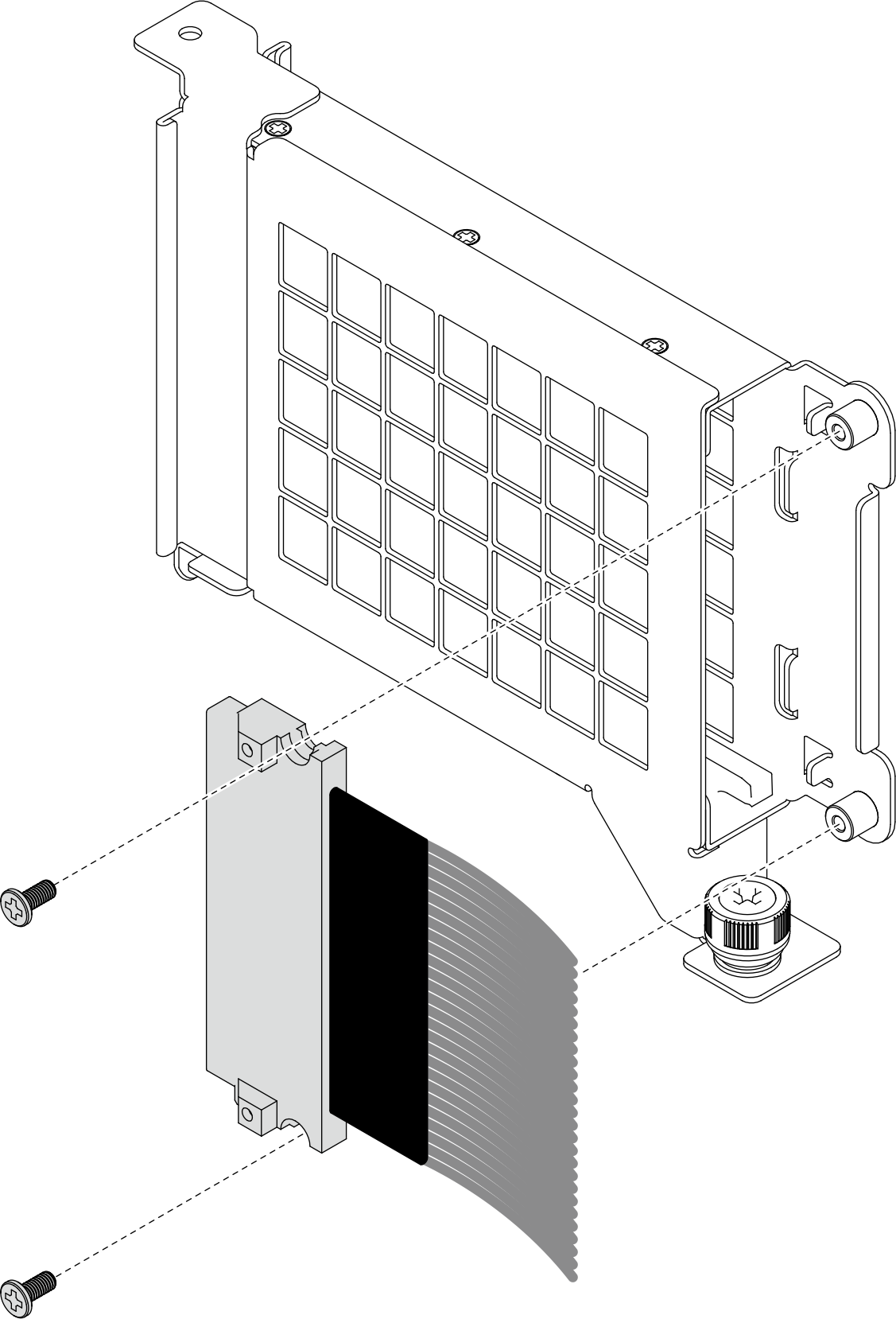
- If necessary, install the OCP cable and secure it to the OCP module cage with two screws.Figure 1. Installing OCP cable
- Install the OCP module cage.Figure 2. Installing OCP module cage
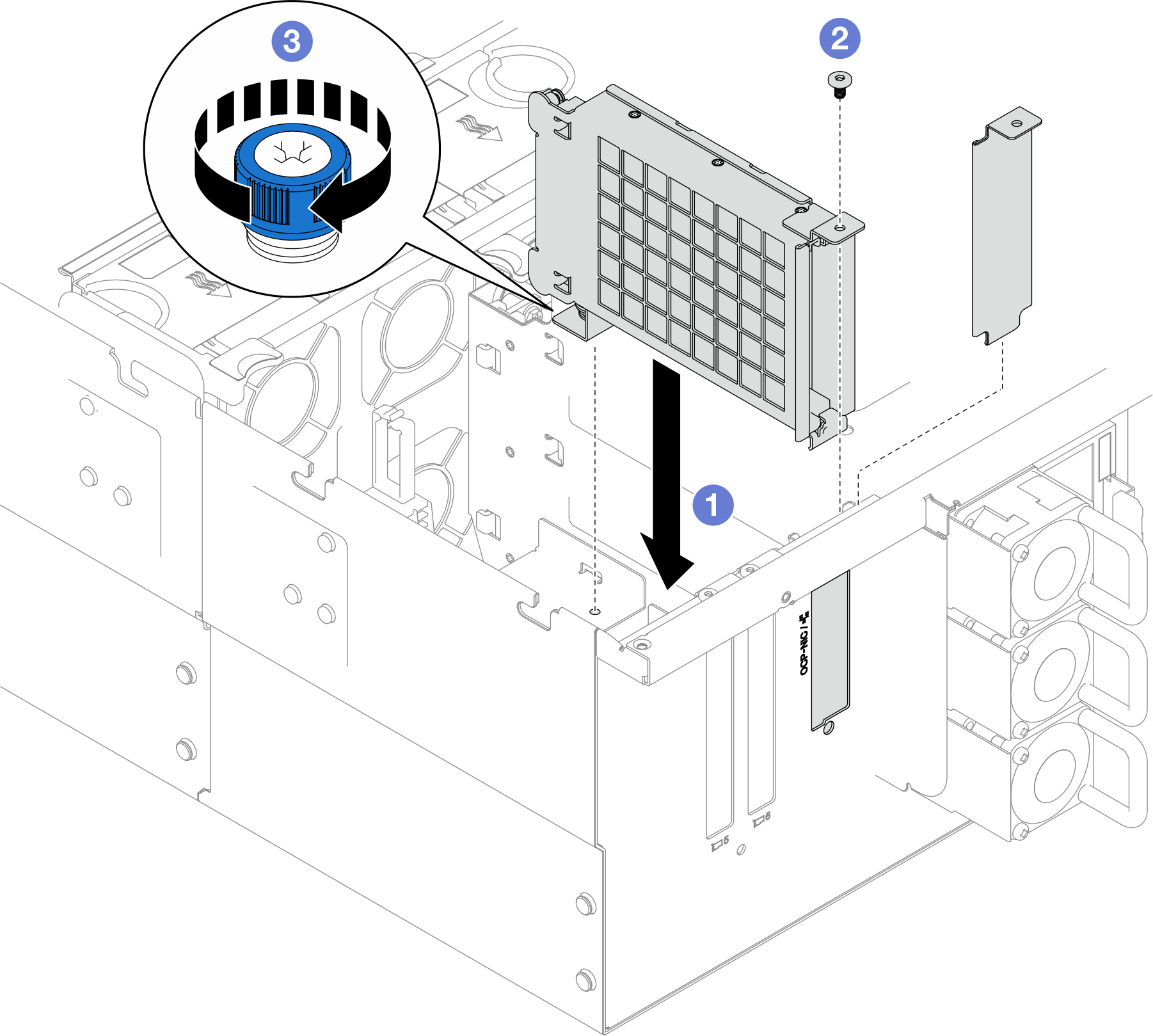
 Align and install the OCP module cage into the chassis.
 Install the screw to secure the OCP module cage.
- Tighten the thumbscrew on the OCP module cage. Use a screwdriver if needed.
After you finish
If you replaced the OCP cable, reinstall the upper processor board (CPU BD) and upper processor board (CPU BD) air baffle. See Install the upper processor board (CPU BD) and Install the upper processor board (CPU BD) air baffle.
Reinstall the rear top cover. See Install the rear top cover.
Reinstall the front top cover. See Install the front top cover.
Reinstall the OCP module. See Install the OCP module.
Complete the parts replacement. See Complete the parts replacement.
Demo video