Install a hot-swap drive
Follow the instructions in this section to install a hot-swap drive into a drive bay and, if necessary, install a 2.5-inch drive into a 3.5-inch drive tray and then a 3.5-inch drive bay.
About this task
Hazardous energy present. Voltages with hazardous energy might cause heating when shorted with metal, which might result in spattered metal, burns, or both.
Read Installation Guidelines and Safety inspection checklist to ensure that you work safely.
Prevent exposure to static electricity, which might lead to system halt and loss of data, by keeping static-sensitive components in their static-protective packages until installation, and handling these devices with an electrostatic-discharge wrist strap or other grounding system.
To make sure that there is adequate system cooling, do not operate the solution for more than two minutes without either a drive or a filler installed in each bay.
If one or more NVMe solid-state drives are to be removed, it is recommended to disable them beforehand via the operating system.
Before removing or making changes to drives, drive controllers (including controllers that are integrated on the system board), drive backplanes or drive cables, back up all important data that is stored on drives.
Before removing any component of a RAID array (drive, RAID card, etc.), back up all RAID configuration information.
Locate the documentation that comes with the drive and follow those instructions in addition to the instructions in this chapter.
The electromagnetic interference (EMI) integrity and cooling of the solution are protected by having all bays and PCI and PCIe slots covered or occupied. When you install a drive, PCI, or PCIe adapter, save the EMC shield and filler panel from the bay or PCI or PCIe adapter slot cover in the event that you later remove the device.
For a complete list of supported optional devices for the server, see: Lenovo ServerProven website
The server supports the installation of 2.5-inch SSDs into a 3.5 inch drive bay through the use of a 3.5-inch drive tray. Refer to the optional part of the procedure.
The drive bays are numbered in installation ordering (starting from number “0”). Follow this sequential order of the drive bays when installing a drive. To locate the drive bays in the server, see Front view.
For hard disk drives with different capacities, install the drive in accordance with the sequential order of the drive bays as well as from the lowest capacity to the highest capacity.
The drives in a single RAID array must be the same type, same size, and same capacity.
Procedure
- (Optional) If necessary, install a 2.5-inch drive into a 3.5-inch drive tray.
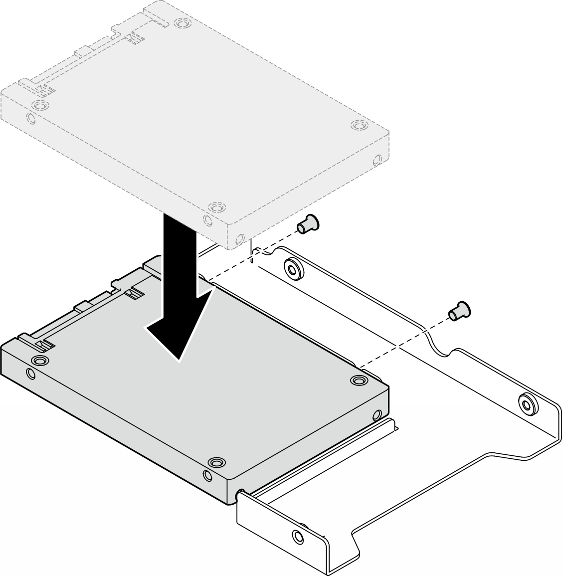
- Align the two screw holes in the drive with the corresponding holes in the drive adapter; then, install the two screws to secure the drive into the drive adapter.Figure 1. Installation of a 2.5-inch drive into a drive adapter
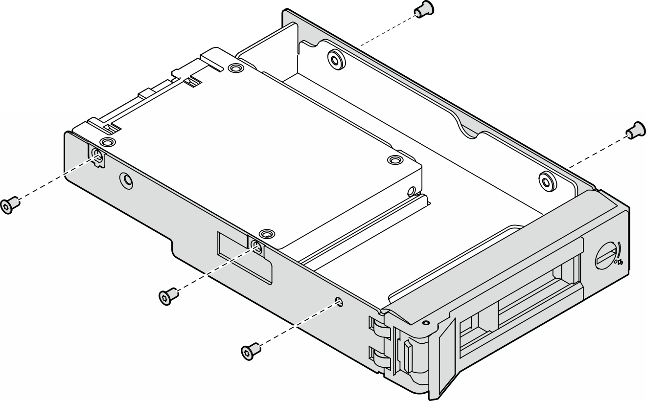
- Position the drive adapter with the drive into the 3.5-inch drive tray. Align the screw holes in the drive adapter and the drive with the corresponding holes in the tray; then, install the five screws to secure the drive adapter and the drive into the tray.Figure 2. Installation of the screws that secure a 2.5-inch drive and a drive adapter
- Align the two screw holes in the drive with the corresponding holes in the drive adapter; then, install the two screws to secure the drive into the drive adapter.
- Slide the drive or drive tray into the drive bay from the front until it snaps into position; then, close the handle completely.
 Ensure that the tray handle is in the open position. Slide the drive into the drive bay until it snaps into position.
 Close the tray handle to lock the drive in place.
Figure 3. Installation of a hot-swap drive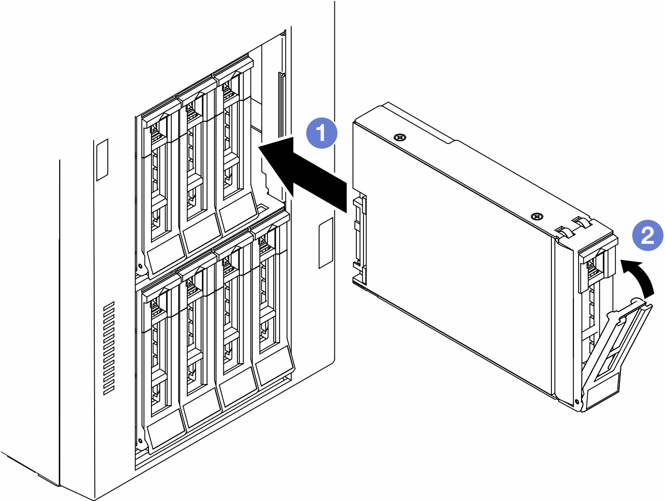
After you finish
- Check the drive status LED to verify that the drive is operating correctly.
If the yellow drive status LED of a drive is lit continuously, that drive is faulty and must be replaced.
If the green drive activity LED is flashing, the drive is being accessed.
If the server is configured for RAID operation through a ThinkSystem RAID adapter, you might have to reconfigure your disk arrays after you install drives. See the ThinkSystem RAID adapter documentation for additional information about RAID operation and complete instructions for using ThinkSystem RAID adapter.
If any of the drive bays are left empty, fill them with drive bay fillers.
Demo video