Replacing an adapter
Use this information to replace an adapter.
The following notes describe the types of adapters that the server supports and other information that you must consider when you replace an adapter:
- To confirm that the server supports the adapter that you are installing, see the Lenovo ServerProven website.
- Locate the documentation that comes with the adapter and follow those instructions in addition to the instructions in this section.
- Do not set the maximum digital video adapter resolution above 1280 x 1024 at 75 Hz for an LCD monitor. This is the highest resolution that is supported for any add-on video adapter that you install in the server.
- Avoid touching the components and gold-edge connectors on the adapter.
- Any high-definition video-out connector or stereo connector on any add-on video adapter is not supported.
- The server uses a rotational interrupt technique to configure PCI adapters so that you can install PCI adapters that do not support sharing of PCI interrupts.
- The server provides two PCI riser slots on the system board. The riser cards provide up to three PCI Express Gen2 adapter slots. The following table lists the PCI-e slots on the riser-card and the system board, the microprocessor to which each slot is connected, and the supported adapters that you can install in each slot:
Table 1. PCI riser slots supported configurations PCI-X riser-card assembly PCI-e slot number Microprocessor to which the slot is connected Configuration 1 Configuration 2 1 1 Microprocessor 1 PCI-e Gen2 x16 (x16 mechanically) full-height, half-length adapter PCI-e Gen2 x8 (x16 mechanically) full-height, half-length adapter 1 2 Microprocessor 1 N/A PCI-e Gen2 x8 (x16 mechanically) low-profile adapter 2 3 Microprocessor 1 PCI-e Gen2 x4 low-profile, internal RAID adapter PCI-e Gen2 x4 low-profile, internal RAID adapter Note: PCI-e slot 3 on PCI-X riser-card assembly 2 is reserved for an optional internal RAID adapter. Do not install any internal RAID adapter in PCI riser-card assembly 1. - The following table lists the option part numbers and CRU part numbers for the network adapters.
Table 2. Network adapters Network Adapters Description Option part number CRU part number QLogic 4Gb PCIe FC single-port HBA 39R6525 39R6526 QLogic 4Gb PCIe FC dual-port HBA 39R6527 39R6528 NetXtreme II 1000 express Ethernet adapter 39Y6066 39Y6070 Intel PRO/1000 PF server adapter 42C1750 42C1752 NetXtreme II 1000 express dual-port Ethernet adapter 42C1780 49Y7947 QLogic 10Gb CNA 42C1800 42C1802 Brocade 10Gb dual-port CNA 42C1820 42C1822 Emulex 4 Gbps FC single-port PCIe HBA 42C2069 43W7510 Emulex 4Gbps FC dual-port PCIe HBA 42C2071 43W7512 Emulex 8Gb FC single-port HBA 42D0485 42D0491 Emulex 8Gb FC dual-port HBA 42D0494 42D0500 QLogic 8Gb FC single-port HBA 42D0501 42D0507 QLogic 8Gb FC dual-port HBA 42D0510 42D0516 6Gb SAS HBA Controller 46M0907 68Y7354 Brocade 8Gb FC single-port HBA 46M6049 46M6061 Brocade 8Gb FC dual-port HBA 46M6050 46M6062 NetXtreme II 1000 express quad-port Ethernet adapter 49Y4220 49Y7949 Intel Ethernet dual-port server adapter I340-T2 49Y4230 49Y4232 Intel Ethernet quad-port server adapter I340-T4 49Y4240 49Y4242 Broadcom NetXtreme II dual-port 10GBaseT adapter 49Y7910 49Y7912 Intel X520-DA2 dual-port 10GbE SFP adapter 49Y7960 49Y7962 Brocade 4Gb FC single-port HBA 59Y1987 59Y1992 Brocade 4Gb FC dual-port HBA 59Y1993 59Y1998 Broadcom NetXtreme I quad-port GbE adapter 90Y9352 90Y9355 Broadcom NetXtreme I dual-port GbE adapter 90Y9370 90Y9373 Emulex 10 GbE virtual fabric adapter III 95Y3762 9573766 Emulex 10 GbE virtual fabric adapter III lite 95Y3768 95Y3766 - Depending on your server models, the server comes with an onboard RAID controller which provides basic RAID levels 0 and 1 functionality. The server supports the following optional RAID adapters that you can purchase for additional RAID support. For configuration information, see the documentation that comes with the adapter or the ServeRAID documentation at the Lenovo Support Portal.AttentionSome cluster solutions require specific code levels or coordinated code updates. If the device is part of a cluster solution, verify that the latest level of code is supported for the cluster solution before you update the code.
Attention
Static electricity that is released to internal server components when the server is powered-on might cause the server to stop, which might result in the loss of data. To avoid this potential problem, always use an electrostatic-discharge wrist strap or other grounding system when working inside the server with the power on.
To install an adapter, complete the following steps:
Note
If your adapter was previously configured, back up or record its configuration information, if possible, before replacing the adapter. See the documentation for your adapter for information and instructions.
- Read the safety information that begins in Safety and Installation guidelines.
- Turn off the server (see Turning off the server) and all attached peripheral devices. Disconnect all power cords; then, disconnect all external cables from the server.
- Carefully turn the server on its side so that it is lying flat, with the cover facing up.AttentionDo not allow the server to fall over.
- Unlock and remove the left-side cover (see Removing the left-side cover).
- Remove the air baffle (see Removing the air baffle).
- Remove the fan assembly (see Removing the fan assembly).
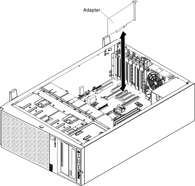
- Remove the existing adaptor (see Removing an adapter).
- See the documentation that comes with the adapter for any cabling instructions and information about jumper or switch settings. (It might be easier for you to route cables before you install the adapter.)
- Touch the static-protective package that contains the adapter; then, remove the adapter from the package.
- Determine the PCI slot into which you will install the adapter.
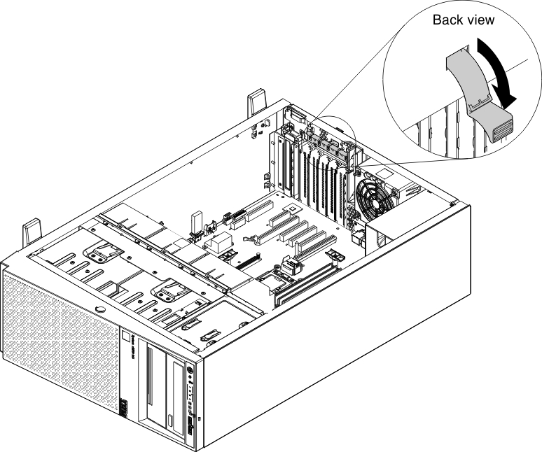
- Press down the latch of the adapter-retention brackets to the open position from the rear side of the server.
- Remove the PCI slot filler, if installed. Keep the filler in a safe place for potential future use.
- Press the adapter firmly into the expansion slot.
 Attention
- Incomplete insertion might cause damage to the system board or the adapter.
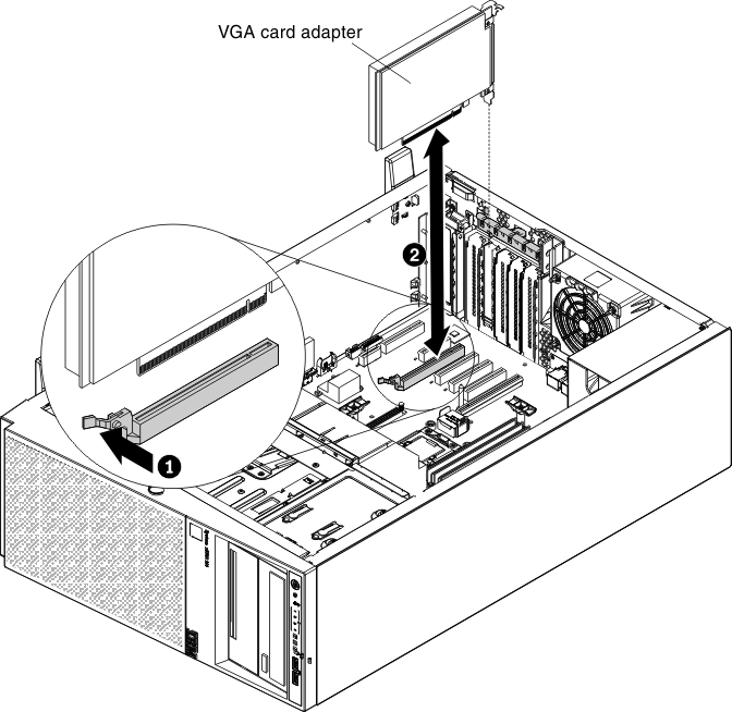
- If you are installing or removing an adaptor into or from PCI slot 4, you have to press the release latch firstly as step 1 of the following illustration.
- Close the adapter-retention bracket.
- Perform any configuration tasks that are required for the adapter.
If you have other devices to install or remove, do so now. Otherwise, go to Completing the installation.
To replace an adapter on the PCI-X riser-card assembly, complete the following steps:
Note
If your adapter was previously configured, back up or record its configuration information, if possible, before replacing the adapter. See the documentation for your adapter for information and instructions.
- Read the safety information that begins in Safety and Installation guidelines.
- Turn off the server (see Turning off the server) and all attached peripheral devices. Disconnect all power cords; then, disconnect all external cables from the server.
- Carefully turn the server on its side so that it is lying flat, with the cover facing up.AttentionDo not allow the server to fall over.
- Unlock and remove the left-side cover (see Removing the left-side cover).
- Remove the air baffle (see Removing the air baffle).
- Remove the fan assembly (see Removing the fan assembly).
- Remove the existing adaptor (see Removing an adapter).
- See the documentation that comes with the adapter for any cabling instructions and information about jumper or switch settings. (It might be easier for you to route cables before you install the adapter.)
- Touch the static-protective package that contains the adapter to any unpainted metal surface on the server; then, remove the adapter from the package.
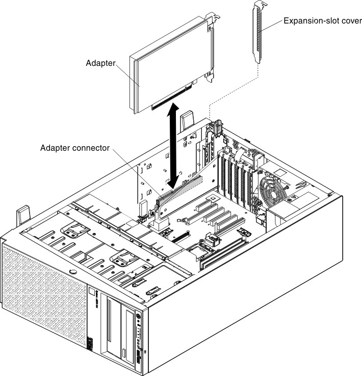
- Locate PCI slot 1 which you will install the adapter into.
- Rotate the adapter-retention brackets on the PCI-X bracket to the open position.NoteRemove the expansion-slot cover if it is installed on the PCI-X bracket and save it for future use.
- Remove the PCI slot filler, if installed. Keep the filler in a safe place for potential future use.
- Press the adapter firmly into the expansion slot.AttentionIncomplete insertion might cause damage to the system board or the adapter.
- Perform any configuration tasks that are required for the adapter.
If you have other devices to install or remove, do so now. Otherwise, go to Completing the installation.
Give documentation feedback