Replacing the hot-swap rear hard disk drive cage
Use this information to replace the hot-swap rear hard disk drive cage.
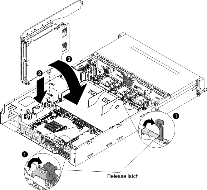
To install the rear hot-swap hard disk drive cage, complete the following steps:
- Rotate the cage inward until it firmly sits into place 3 .Figure 1. Rear hard disk drive cage installation
- Remove the power cable that currently connects the hot-swap hard disk drive backplane in the server to the power-paddle card.
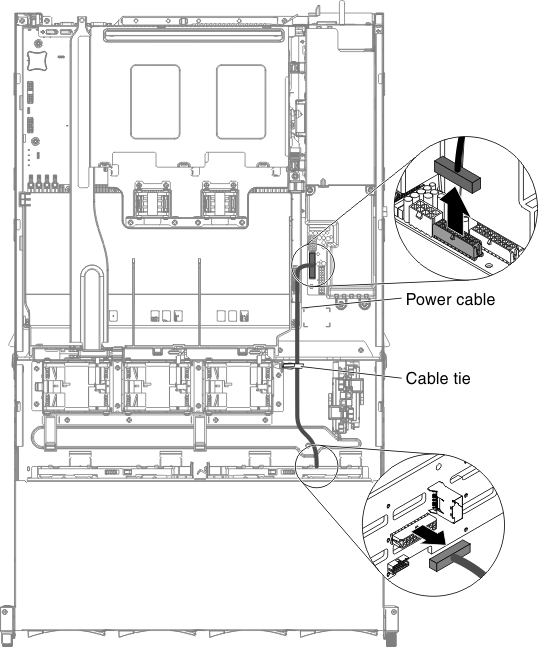
- Type 1 - SATAFigure 2. Cable routing
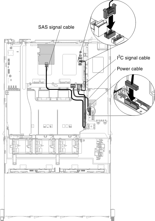
- Type 2 - SASFigure 3. Cable routing
- Type 1 - SATA
- Connect cables to the backplane.
- Type 1 - SATA
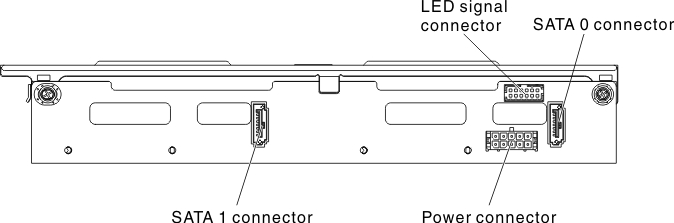
- Connect the LED signal, SATA signal and power cables to the backplane.Figure 4. Type 1
- Insert the hot-swap backplane onto the rear hard disk drive cage (see Replacing the hot-swap backplane on the rear hard disk drive cage
- Connect the other end of the LED signal cable to the hot-swap hard disk drive backplane in the server.
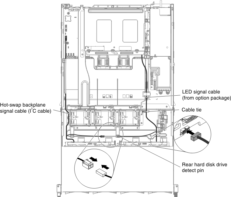
- Find the rear hard disk drive detect pin of the hot-swap backplane signal (I2C) cable located near the system fan cage; then, connect with the rear hard disk drive detect pin of the LED signal cable from the option package.Figure 5. Cable routing
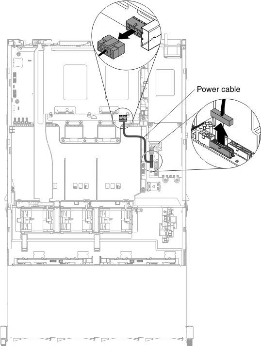
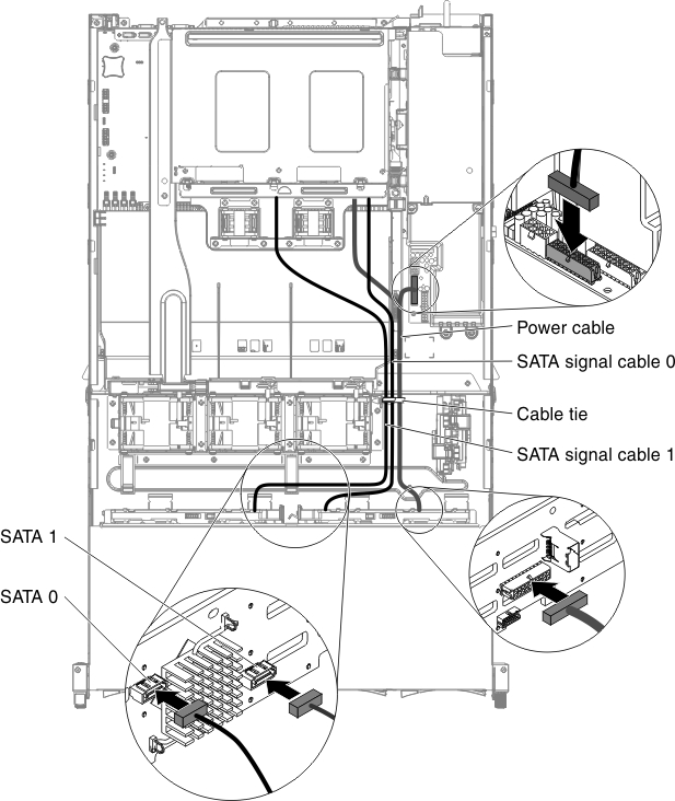
- Connect the other end of the SATA signal and power cables to the power paddle card and hot-swap hard disk drive backplane in the server. Make sure the labels of both connectors are matched.Figure 6. Cable routing
 NoteMake sure that Port 1 is connected to Port 1 for both backplanes. Likewise, Port 0 is connected to Port 0 for both backplanes.Figure 7. Cable connection
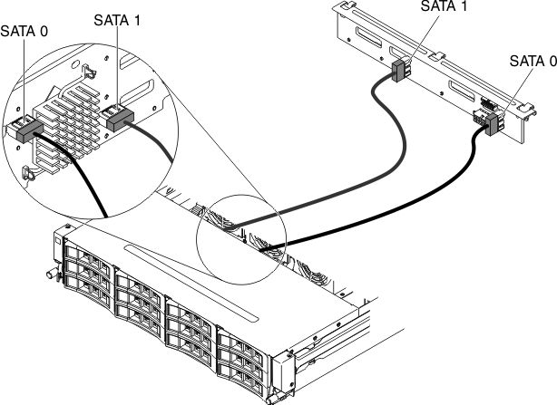 NoteMake sure the cables are routed in the proper locations without blocking the airflow. It is recommended to press all the cables downwards to make the cable routing easier. Secure the cables with any cable retention clips.
- Connect the LED signal, SATA signal and power cables to the backplane.
- Type 2 - SAS
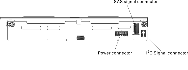
- Connect the I2C signal, SAS signal and power cables to the backplane.Figure 8. Type 2
- Insert the hot-swap backplane onto the rear hard disk drive cage (see Replacing the hot-swap backplane on the rear hard disk drive cage.
- Connect the other ends of the I2C signal, SAS signal and power cables.Figure 9. Cable routing
 NoteMake sure the cables are routed in the proper locations without blocking the airflow. It is recommended to press all the cables downwards to make the cable routing easier. Secure the cables with any cable retention clips.
- Connect the I2C signal, SAS signal and power cables to the backplane.
- Type 1 - SATA
Give documentation feedback