Replacing the video and USB breakout signal cable
Use this information to replace the video and USB breakout signal cable.
To install the video and USB breakout signal cable, complete the following steps:
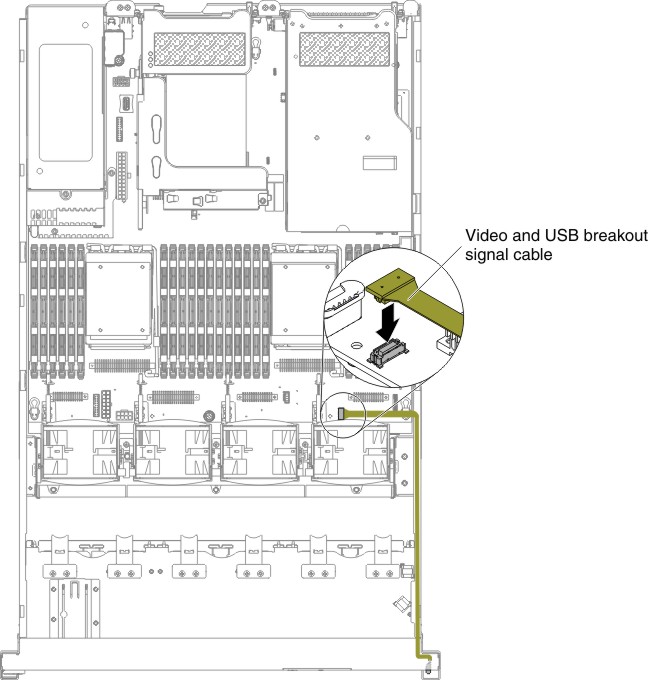
- Connect the video and USB breakout signal cable to the system board. Figure 1. Connecting the video and USB breakout signal cable to the system board
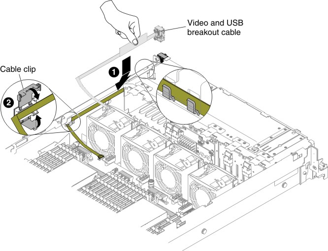
- Route the video and USB breakout signal cable along the chassis. Make sure it passes through the relevant cable clips.Figure 2. Video and USB breakout signal cable routing
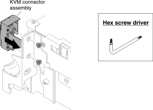
- Reconnect the video and USB breakout signal cable to the KVM assembly; then, install the two screws to secure the KVM assembly to the side of the chassis.NoteUse the hex screw driver to install the two screws.Figure 3. KVM assembly installation
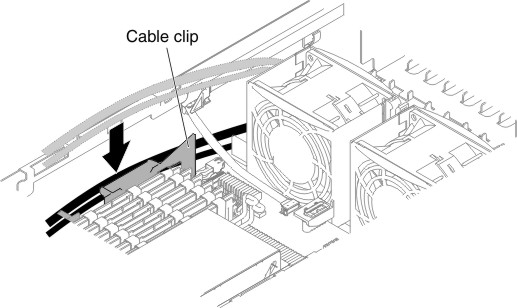
- Insert the SAS, power and operator information panel cables into the cable clips. The power cable is present when the third backplane is installed in the server. Figure 4. SAS, power and operator information panel cable insertion
Give documentation feedback