Install the enclosure in the rack
To install the enclosure in the rack, follow the instructions that are provided below.
About this task

Read Installation Guidelines and Safety inspection checklist to ensure that you work safely.
- When moving the enclosure for long distance or larger movements, lift tool and lift handles should be used. Lifting manually without tools can only be done when moving the enclosure for short distance. When lifting manually, make sure not to grab the top edges on the front and rear of the enclosure to avoid damages.
 Figure 1. Restricted area for manual lifting (short distance only)
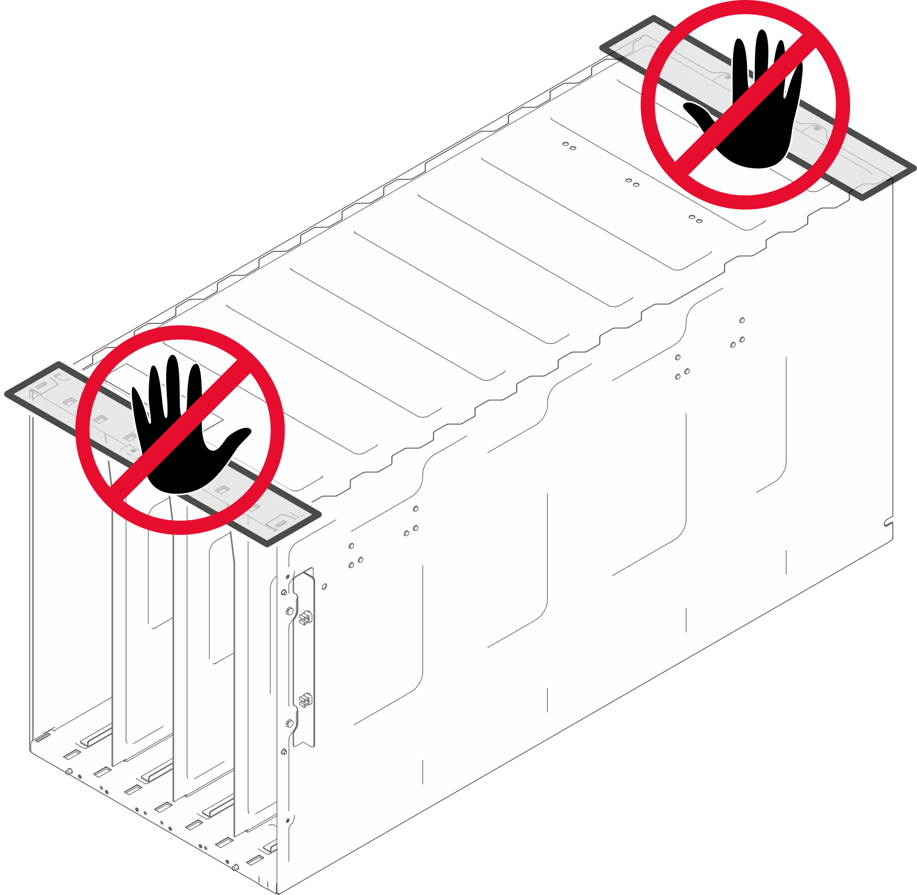
- A video of this procedure is available at YouTube.
Procedure
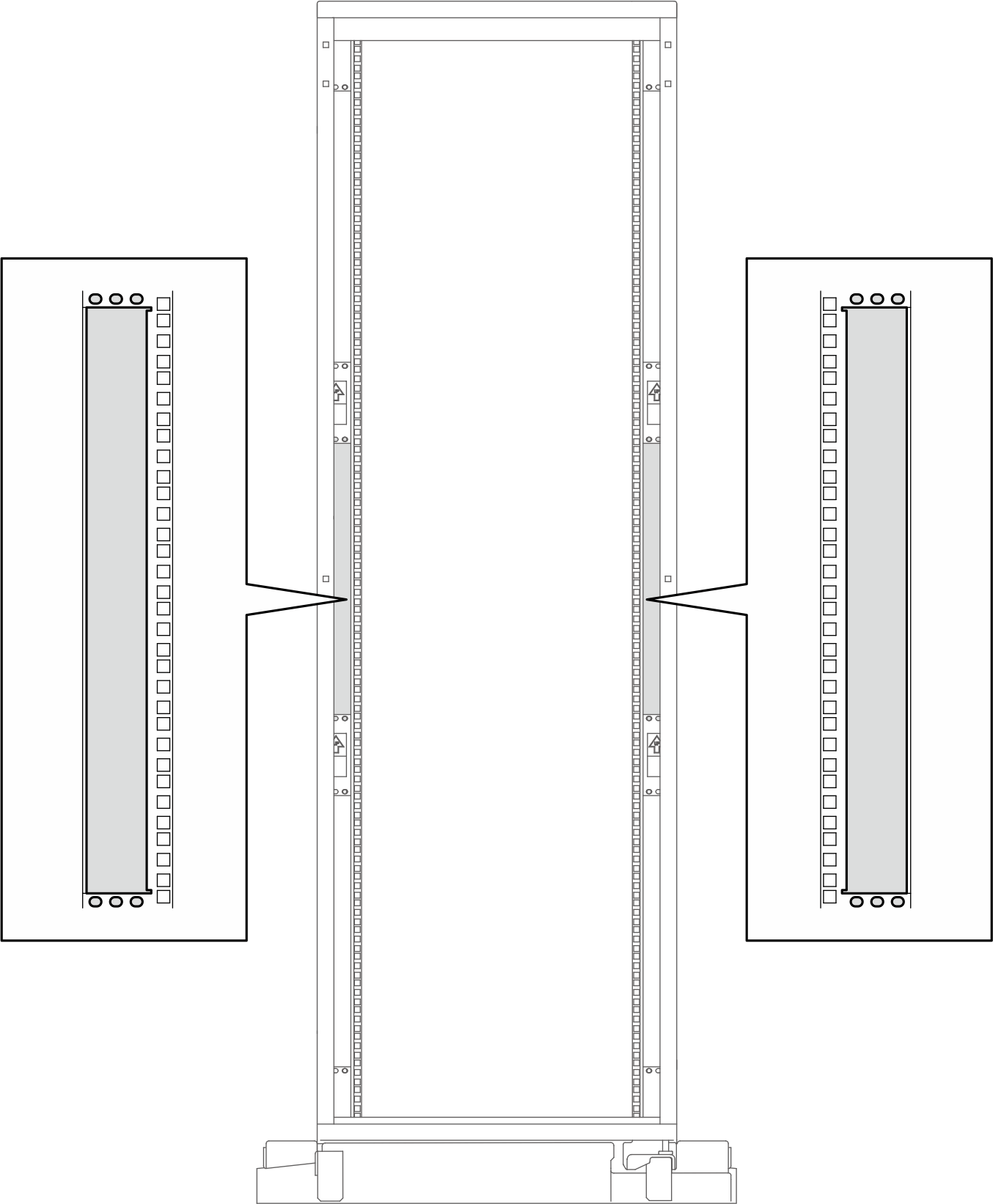
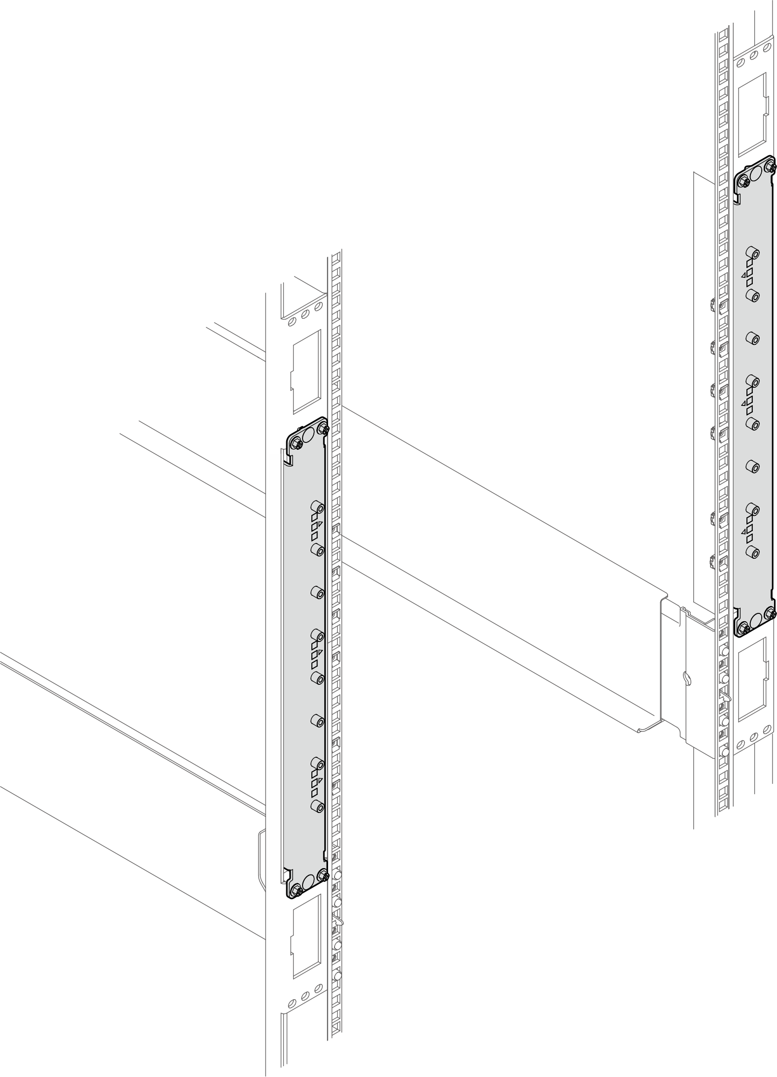
- From the rear of the rack, locate the place and screw holes for enhancement kit installation on the left and right rack posts.Figure 2. Enhancement installation location on rack posts from the rack rear
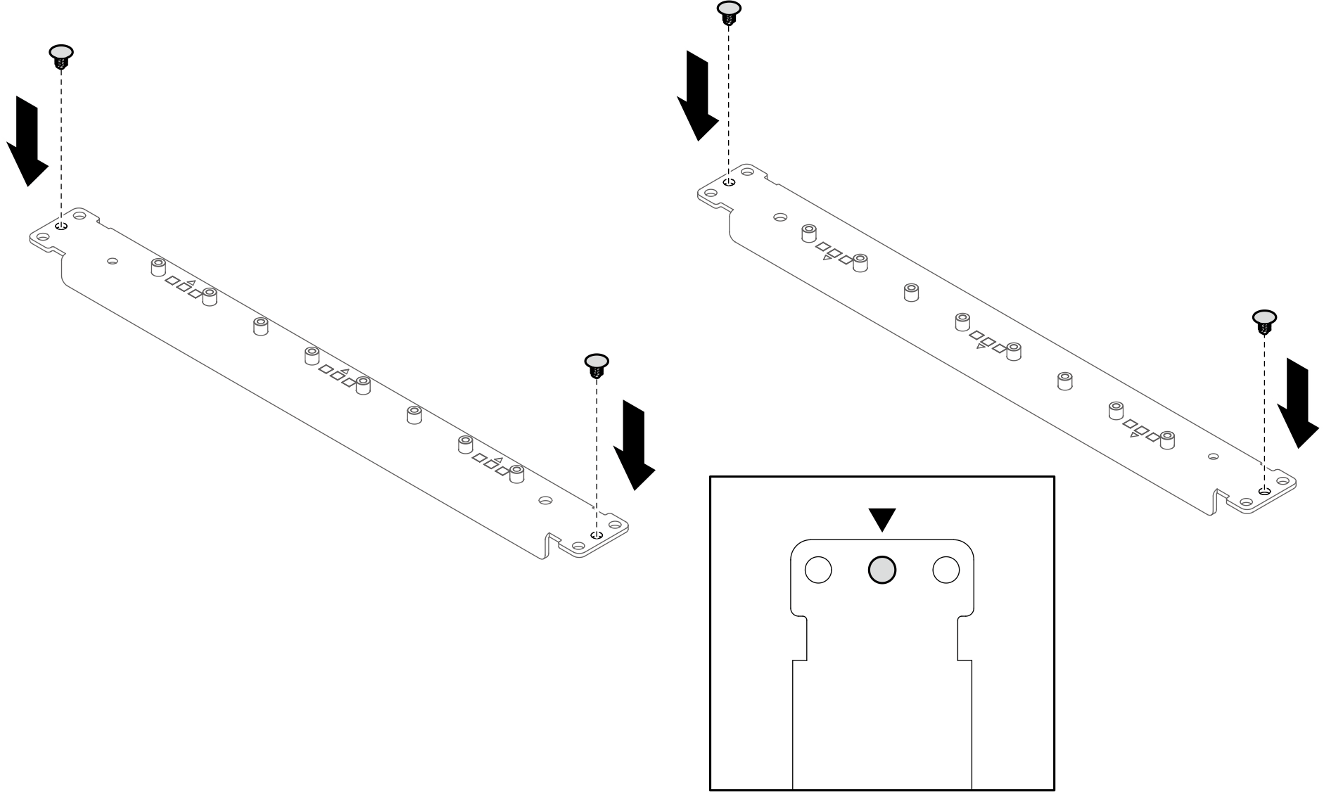
- 42U rack ONLY There are three screw holes on the front end and rear end of the enhancement bracket. Install plastic rivets to the middle screw holes (two rivets per bracket).Figure 3. Installing plastic rivets to enhancement brackets
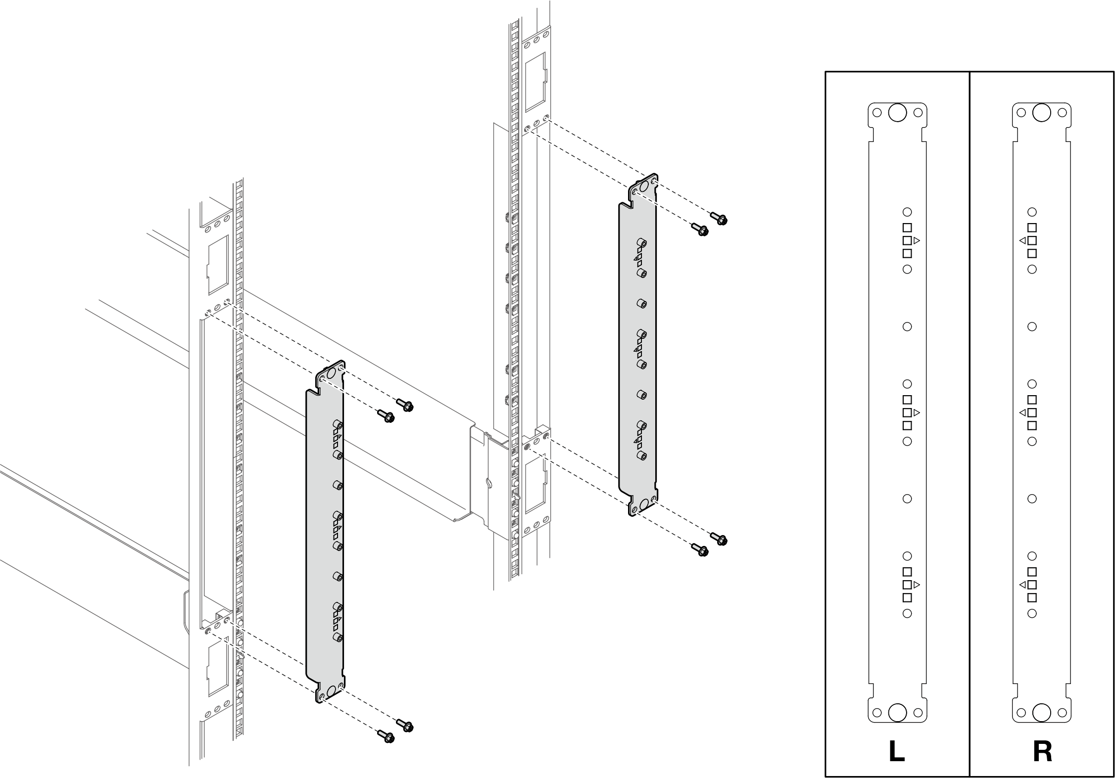
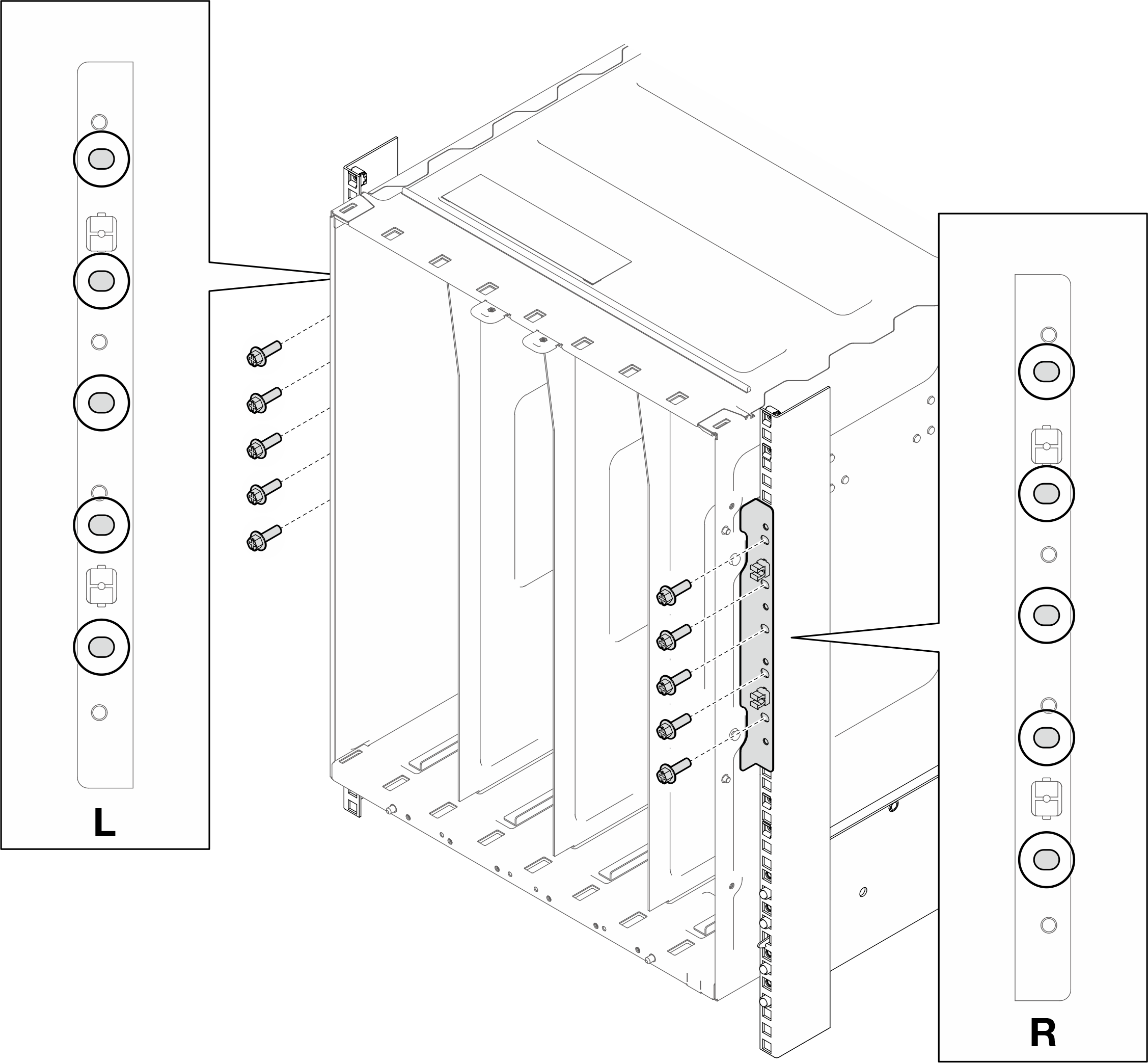
- Install the enhancement kit to the left and right rack posts. Install four screws on each rack posts to secure the enhancement kits to the rack posts.Figure 4. Installing enhancement kits
- Make sure the enhancement kits are installed properly.Figure 5. Rack rear installed with enhancement kits
- Install the rear support bracket.
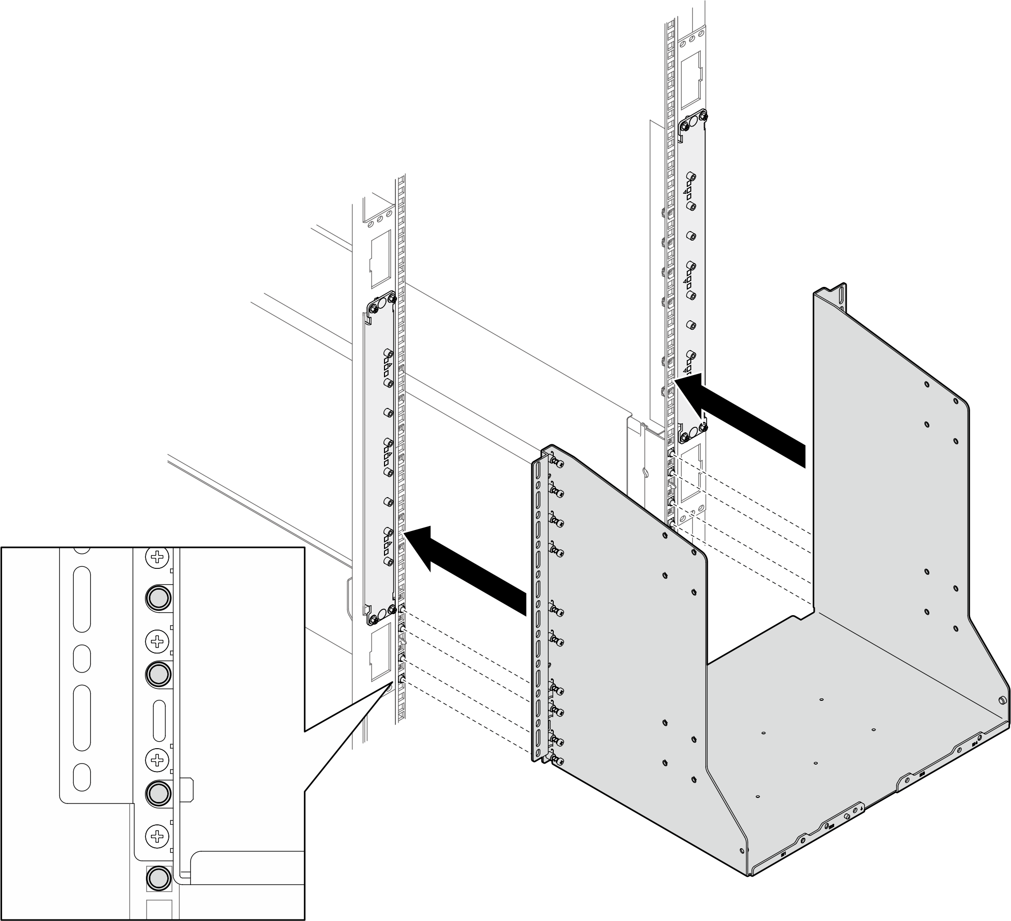
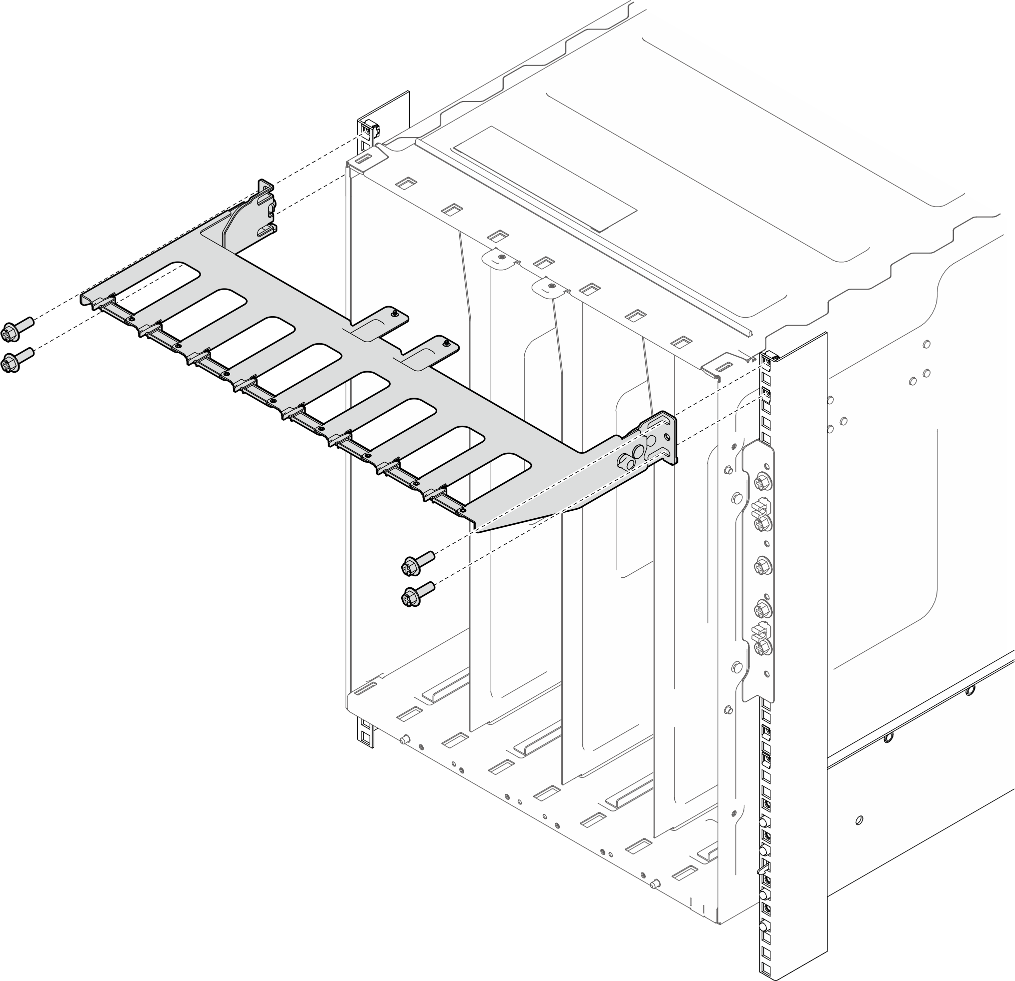
- Align the rear support bracket to the rail guide pins.Figure 6. Aligning rear support bracket to the rail guide pins
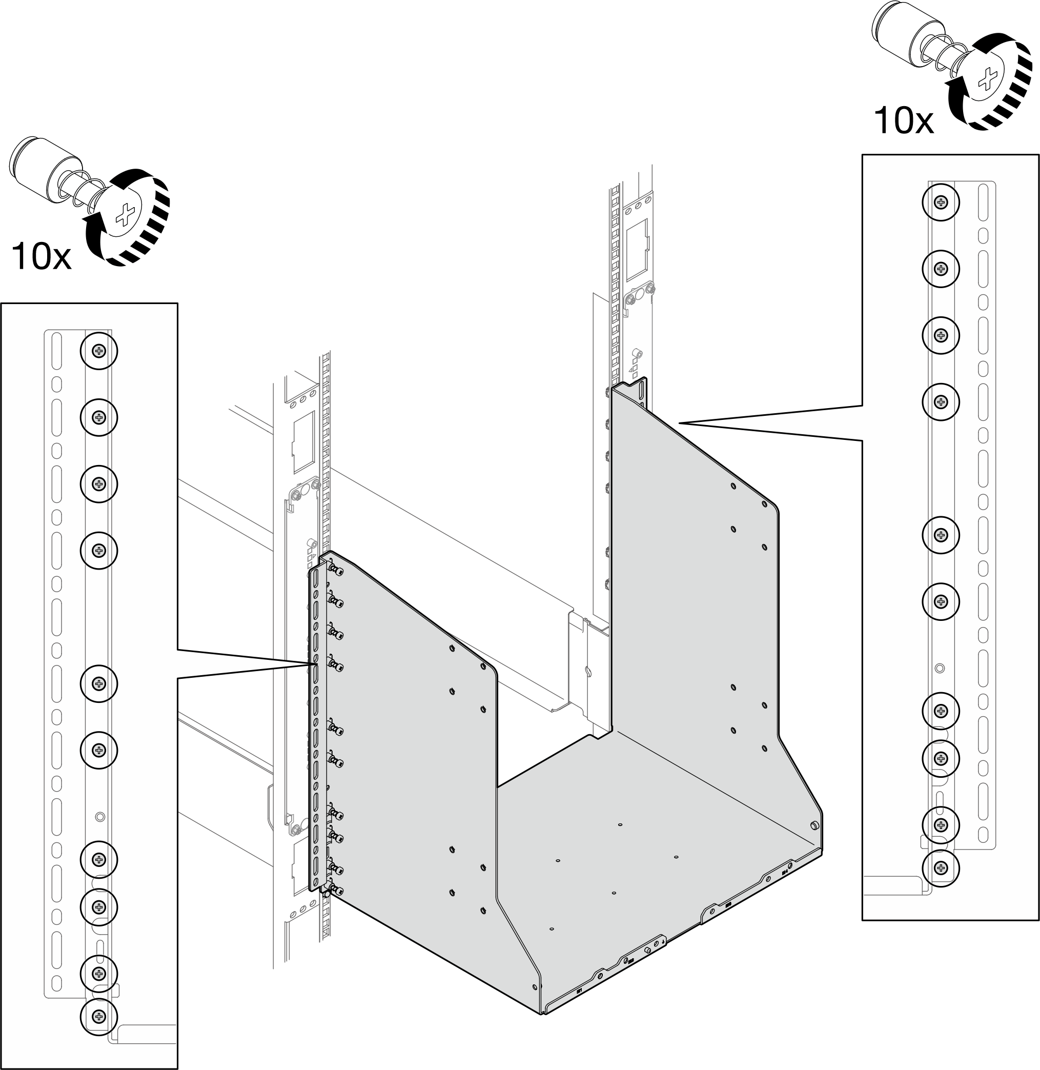
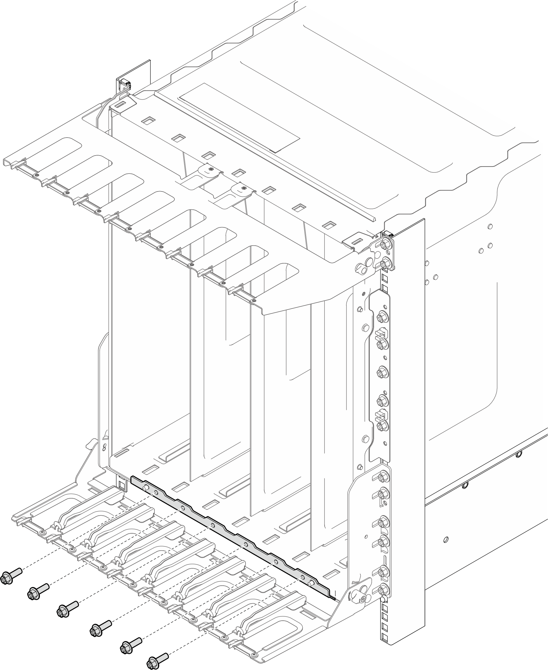
- Fasten ten screws on each rack post to secure the rear support bracket to the rack.Figure 7. Installing screws to secure the rear support bracket
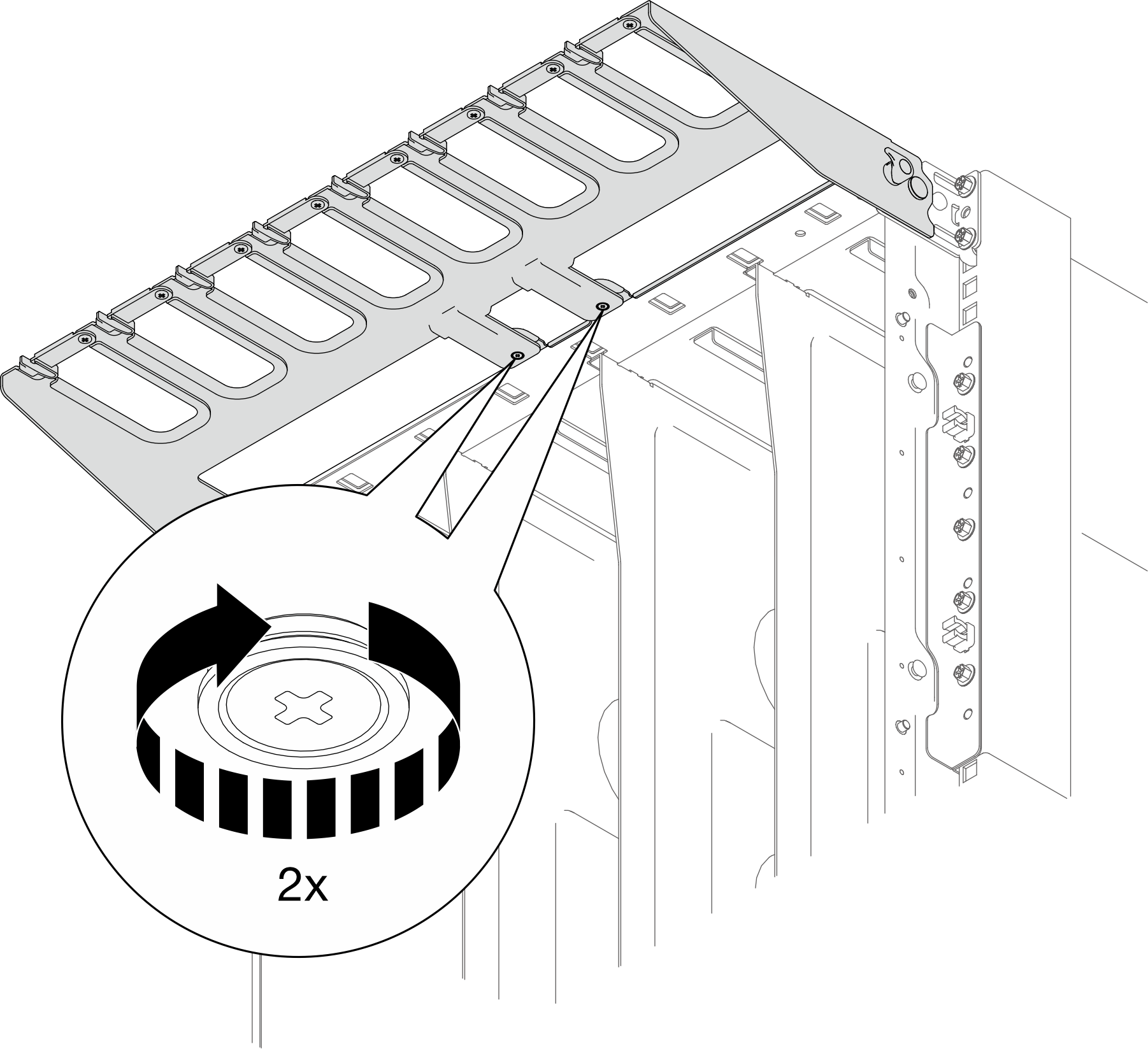
- Install screws to secure the rear support bracket to the enhancement kit.Note
V: When an enhancement kit screw hole is shown within the support bracket opening, install screw to the support bracket opening.
X: When no screw holes is shown within the support bracket opening, there is no need to install screw.
1: Enhancement kit screw hole
Figure 8. Installing the rear supporting bracket to the enhancement kit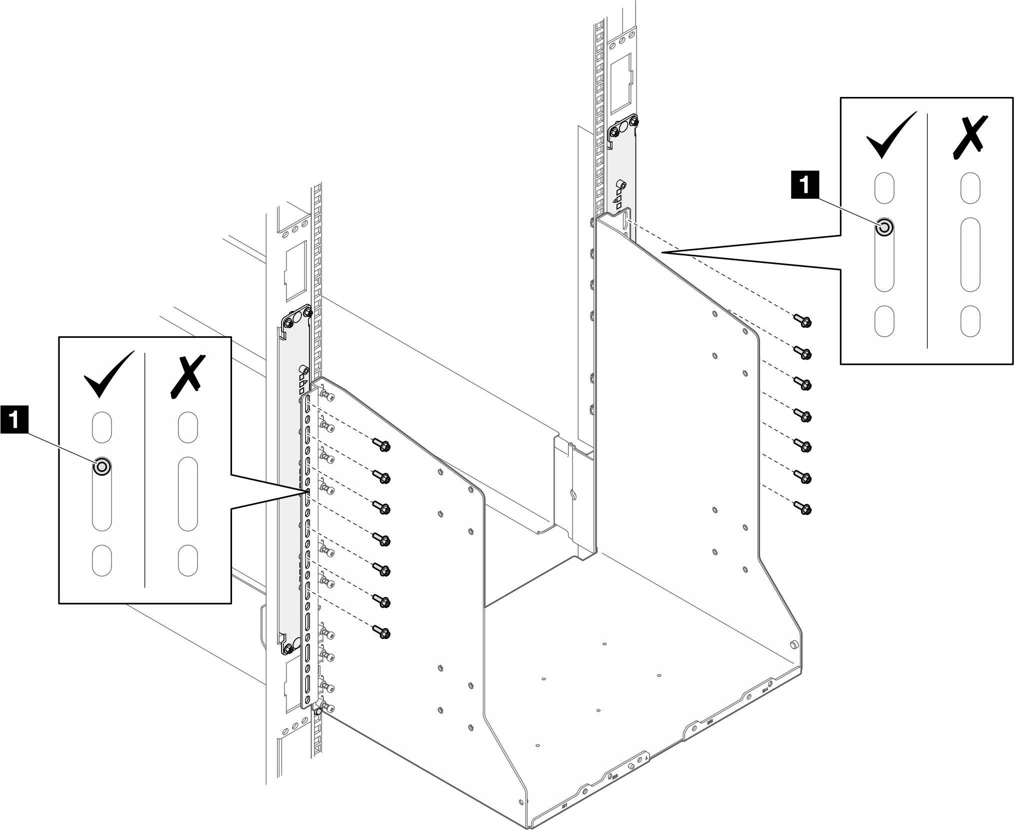
- Align the rear support bracket to the rail guide pins.
- Attach four lift handles to the enclosure.
 Press the latches on the sides of f the lift handle.
 Align slots on the lift handle with posts on the enclosure and install the lift handle to the enclosure. Then, slide the lift handle upwards to secure it in place.
Figure 9. Installing lift handles to the enclosure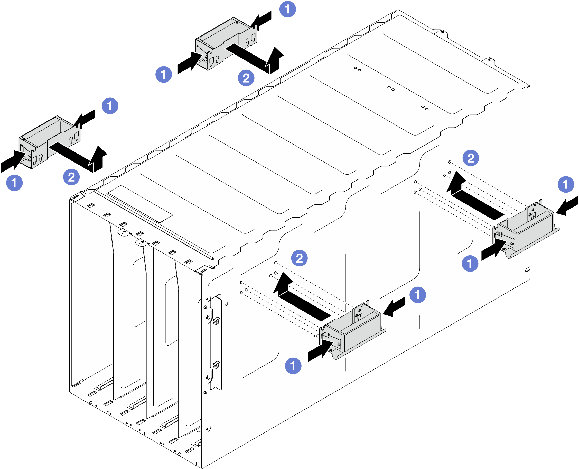
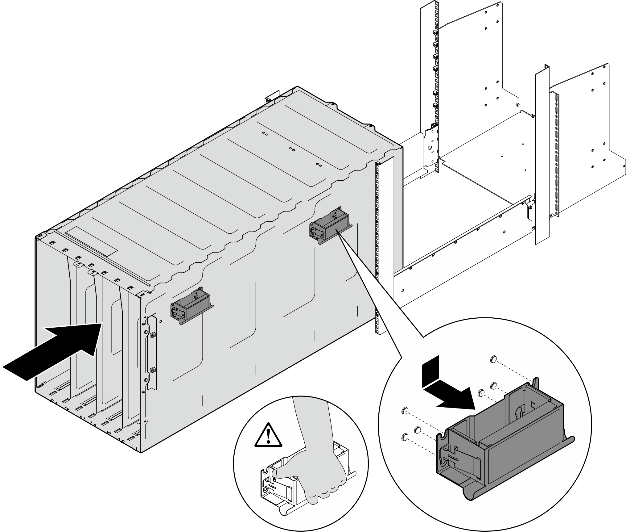
- From the front of the rack, carefully put the enclosure into the rack and slide the enclosure until rear lift handles are near front rack rails; then, remove rear lift handles from both sides.Figure 10. Removing the rear lift handles from the enclosure
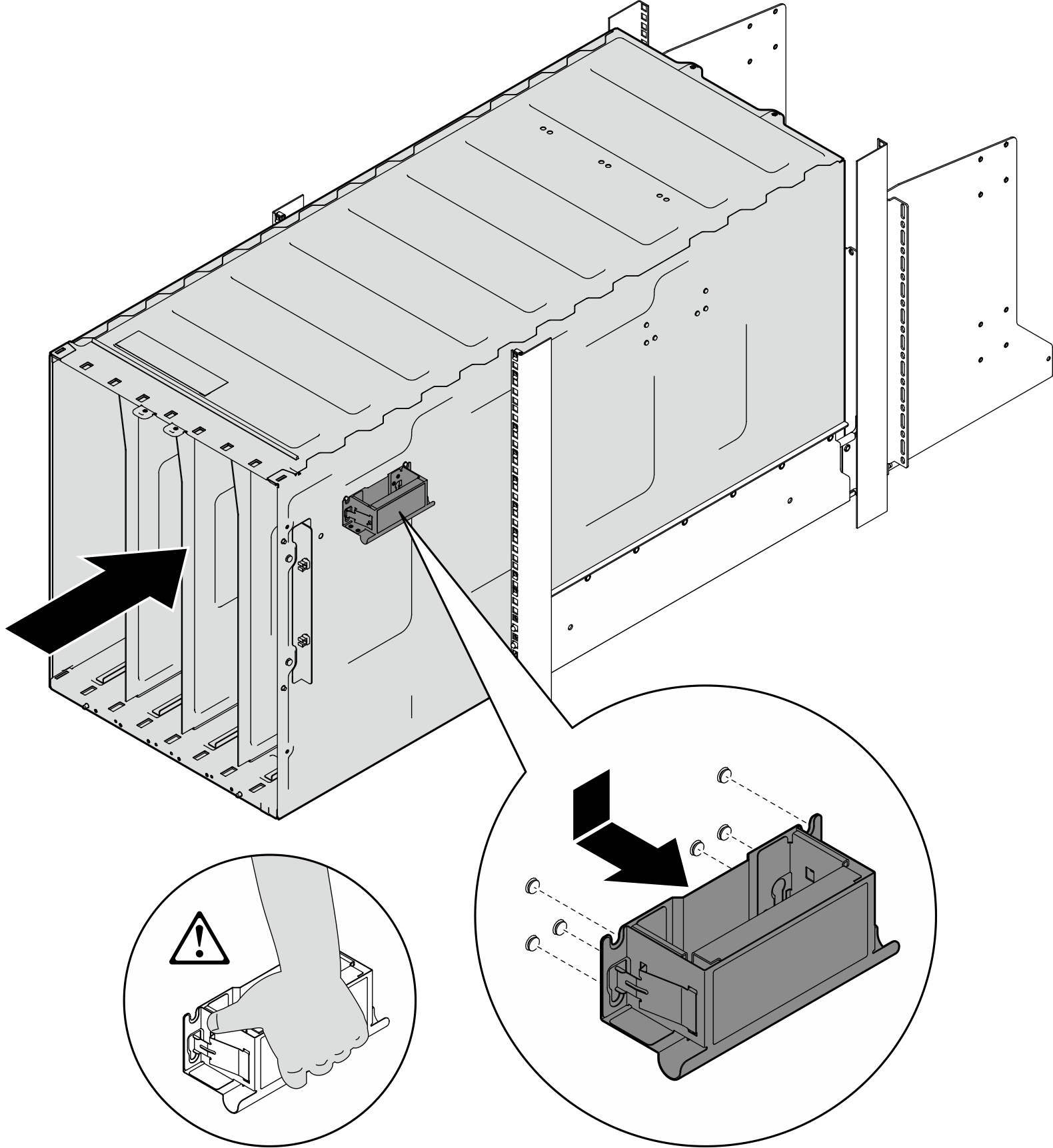
- Slide the enclosure farther into the rack until front lift handles are near front rack rails; then, remove front lift handles from both sides.Figure 11. Removing front lift handles from the enclosure
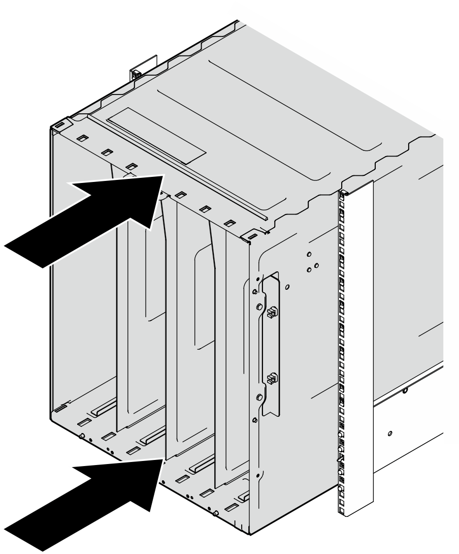
- From the front of the rack, install the enclosure to the rack.Figure 12. Installing enclosure to the rack
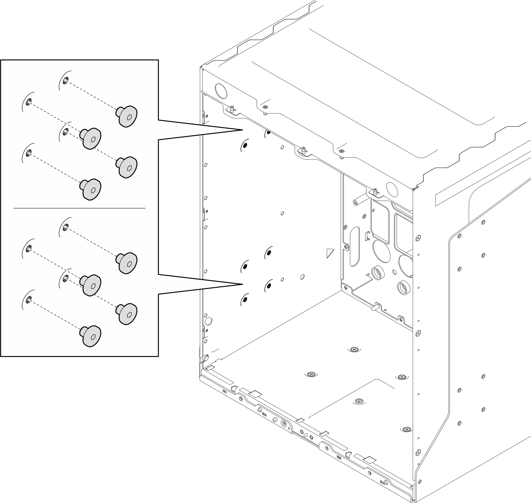
- Install eight screws to the inner right side to secure the enclosure to the rear support bracket.Figure 13. Installing screws to inner right side of the enclosure
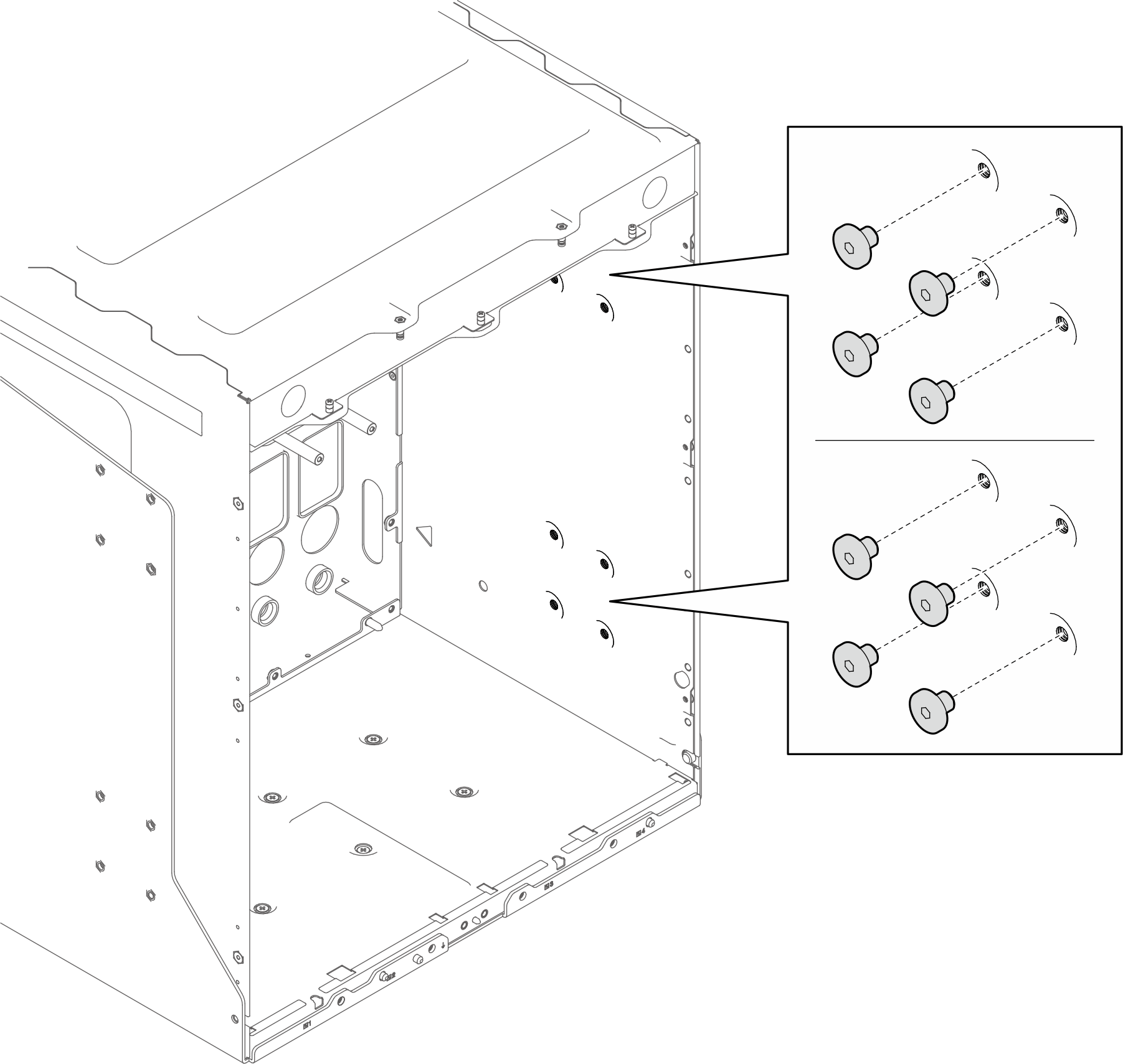
- Install eight screws to the inner left side to secure the rear support bracket to the enclosure.Figure 14. Installing screws to inner left side of the enclosure
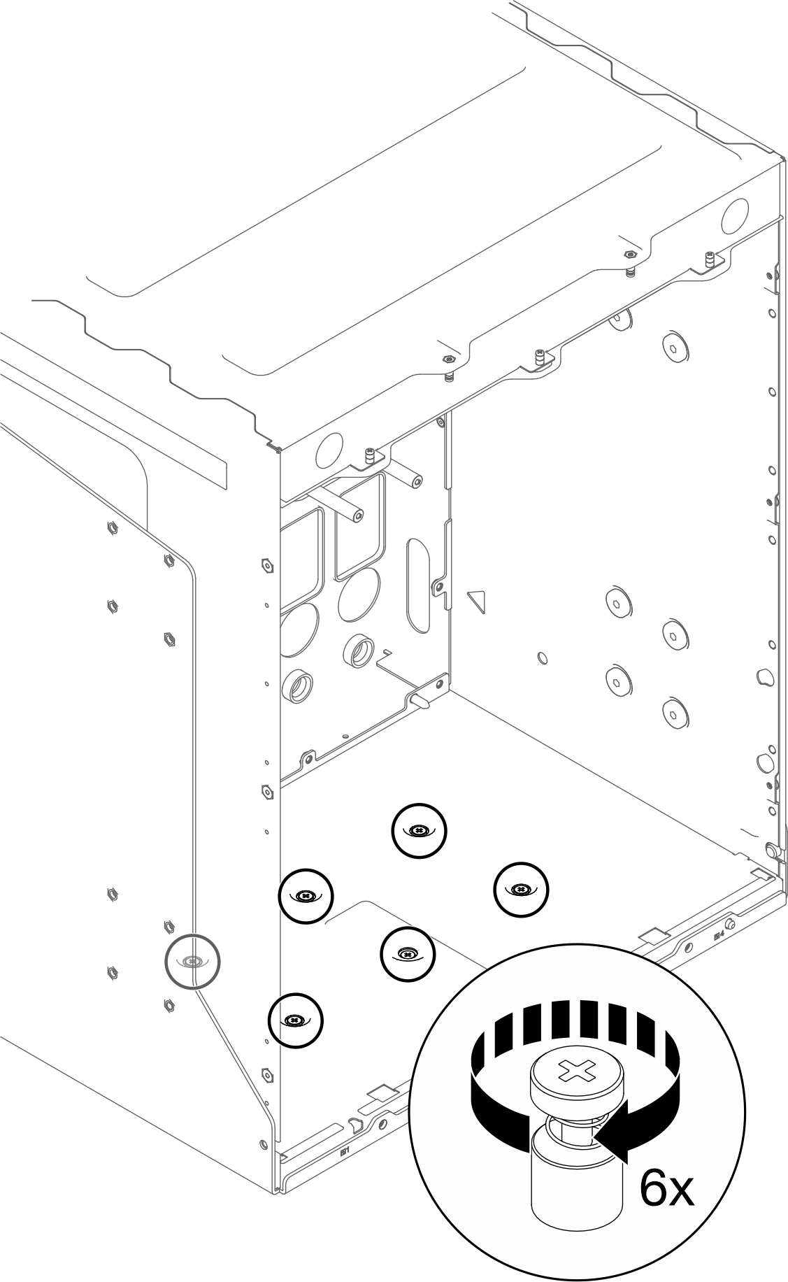
- From the inside of the rear of the enclosure, fasten six screws to secure the rear support bracket to bottom side of the enclosure.Figure 15. Securing the rear support bracket to the bottom side of the enclosure
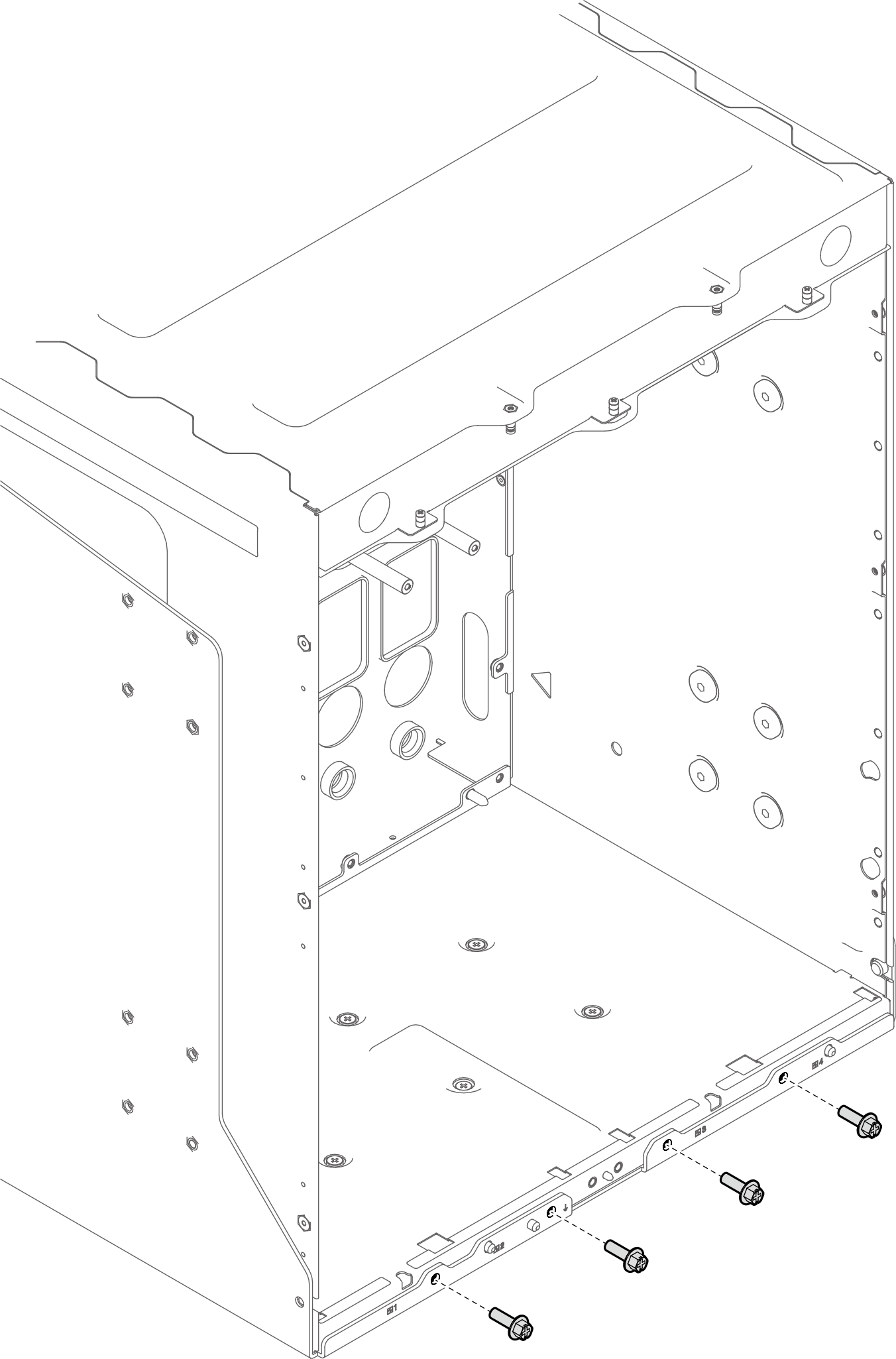
- Install four screws to secure the rear support bracket to enclosure rear end .Figure 16. Securing rear support bracket to the enclosure rear end
- From the front of the enclosure, install the EIA brackets to the enclosure. Attach the EIA brackets to the rack posts, and install five screws on each rack post to secure the EIA brackets to the rack.Figure 17. Installing EIA brackets to the enclosure front
- Install the top front support bracket.
- Install four screws to secure the top front support bracket to the enclosure.Figure 18. Installing top front support bracket
- Install two screws from underneath the top front support bracket.Figure 19. Installing two screws from underneath the top front support bracket.
- Install four screws to secure the top front support bracket to the enclosure.
- Installing bottom front support bracket.
- Install six screws on each rack post to secure the bottom front support bracket to the enclosure.Figure 20. Installing bottom front support bracket

- Install six screws to secure the bottom support bracket to the enclosure front end.Figure 21. Installing bottom support bracket
- Install six screws on each rack post to secure the bottom front support bracket to the enclosure.
- Install EIA covers to the rack.
- Place the EIA brackets to the rack posts.Figure 22. Installing EIA covers
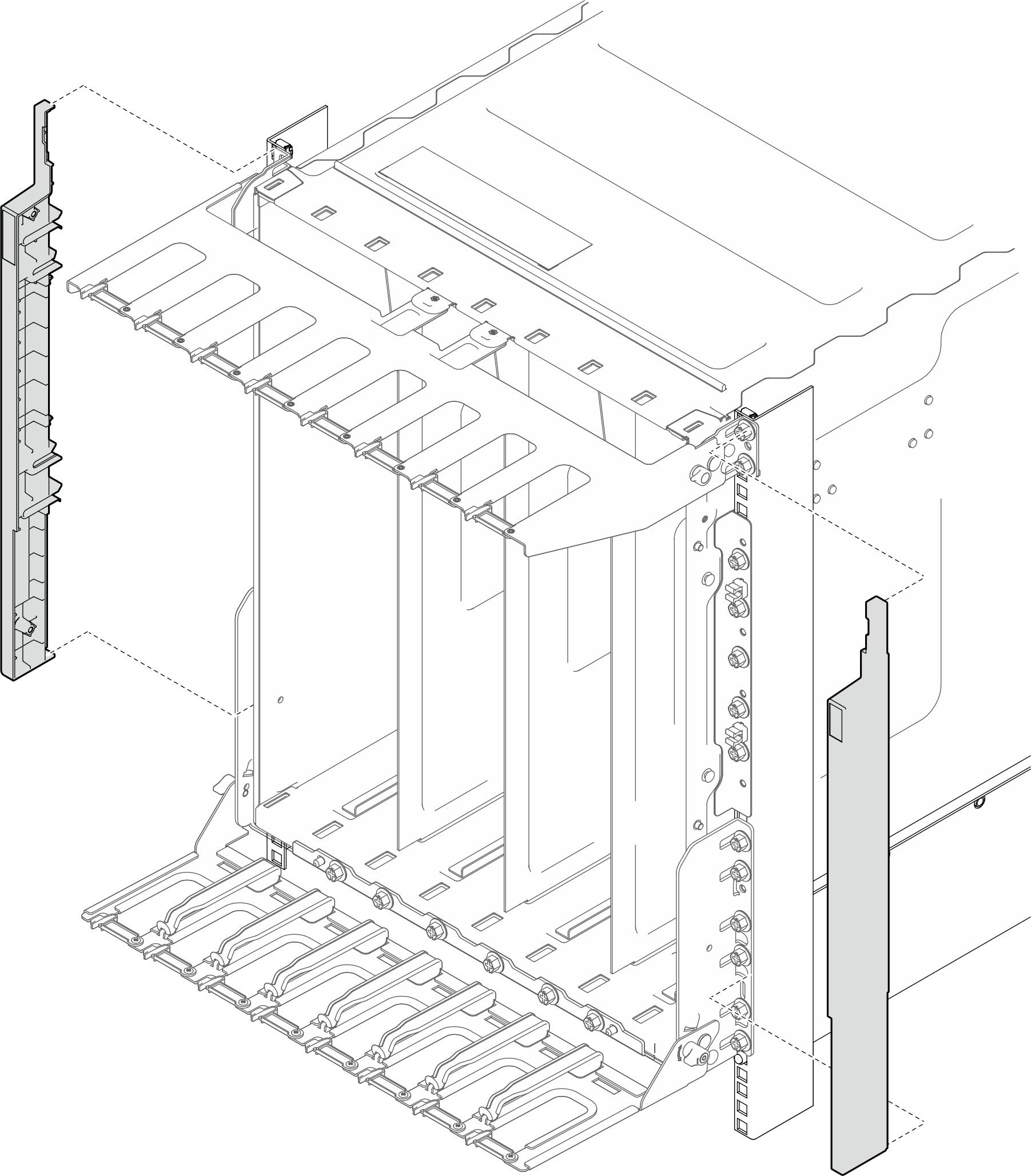
- Install two screws to each rack post to secure the EIA covers, with a torque screwdriver set to the torque 5.0+/- 0.5 lbf-in (or 0.55+/- 0.05 N-M).Figure 23. Securing EIA covers to rack
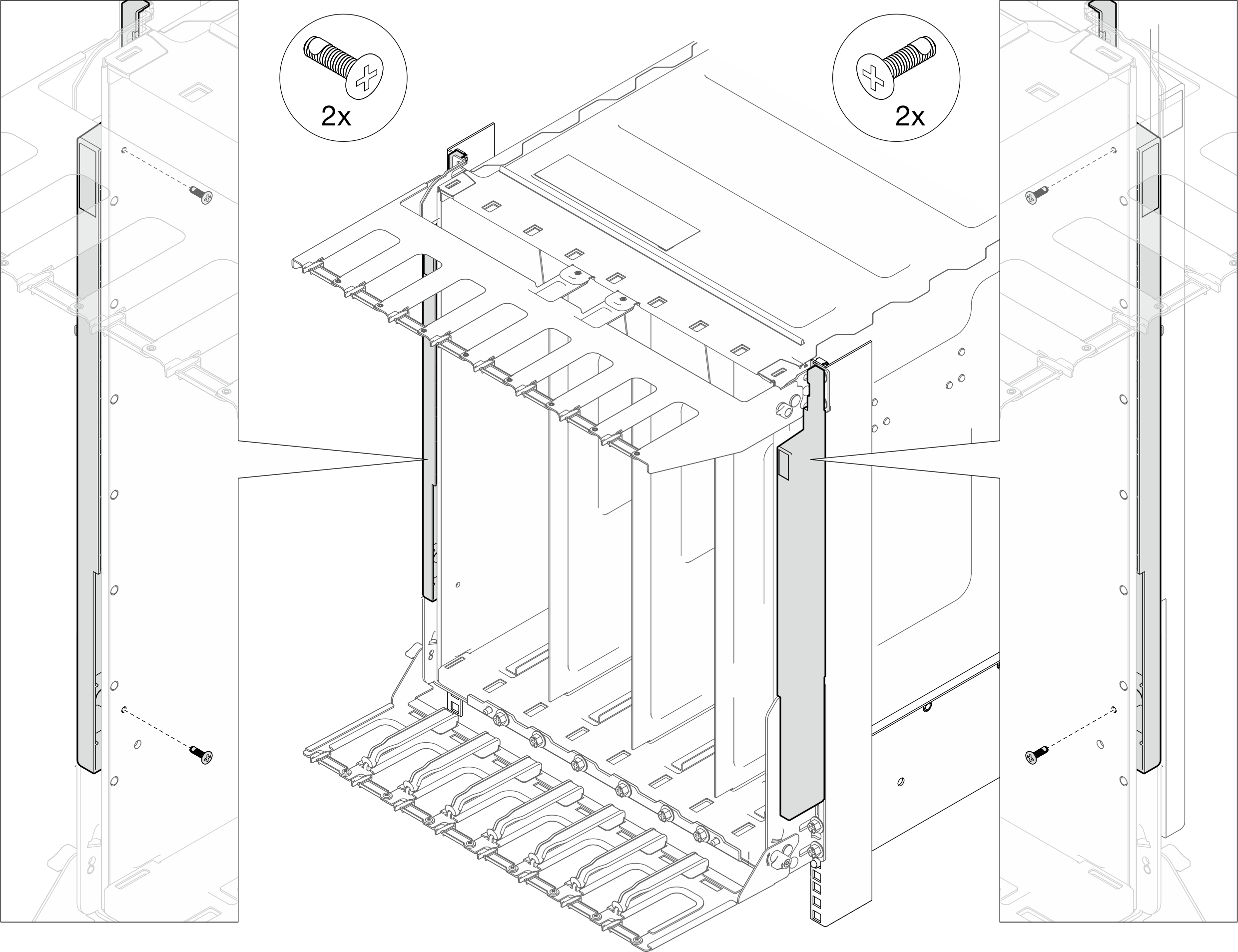
- Place the EIA brackets to the rack posts.
Install the enclosure mid-plate assembly. See Install the mid-plate assembly.
Install upper and lower manifold. See Install the manifold.
Install all Power Conversion Station (PCS) cage. See Install a Power Conversion Station (PCS) cage.
Install all Power Conversion Stations (PCS). See Install a Power Conversion Station (PCS).
Install the SMM3. See Install the SMM3.
Install the blank filler. See Install the blank filler.
Install all trays into the front of the enclosure. See Install a tray in the enclosure.
- Install any other required components.
- Connect all required cables.
- Connect the enclosure to power.
- Update the solution firmware to the latest level.
- Update the serial number, machine type, and UUID on the label of the new enclosure to SMM3:
Log in to the SMM3 web interface.
Go to , and update serial number, machine type, and UUID.
- Restart any nodes that you shut down. See Power on the solution.
- The SMM3 is powered-on automatically.