Install the system I/O board
Follow the instructions in this section to install the system I/O board, also known as Datacenter Secure Control Module (DC-SCM).
About this task
This task must be operated by trained technicians that are certified by Lenovo Service. Do not attempt to remove or install it without proper training and qualification.
Read Installation Guidelines and Safety inspection checklist to ensure that you work safely.
Power off the server and peripheral devices and disconnect the power cords and all external cables. See Power off the server.
Keep static-sensitive parts in their static-protective packages until installation to prevent exposure to static electricity. Handle the parts with an electrostatic-discharge wrist strap or other grounding systems. Place the parts on a static-protective surface.
To avoid component damage, connect the power cords last.
Go to Drivers and Software download website for ThinkSystem SR630 V4 to see the latest firmware and driver updates for your server.
Go to Update the firmware for more information on firmware updating tools.
Procedure
- Install the new system I/O board onto the processor board.Figure 1. Installing the system I/O board onto the processor board
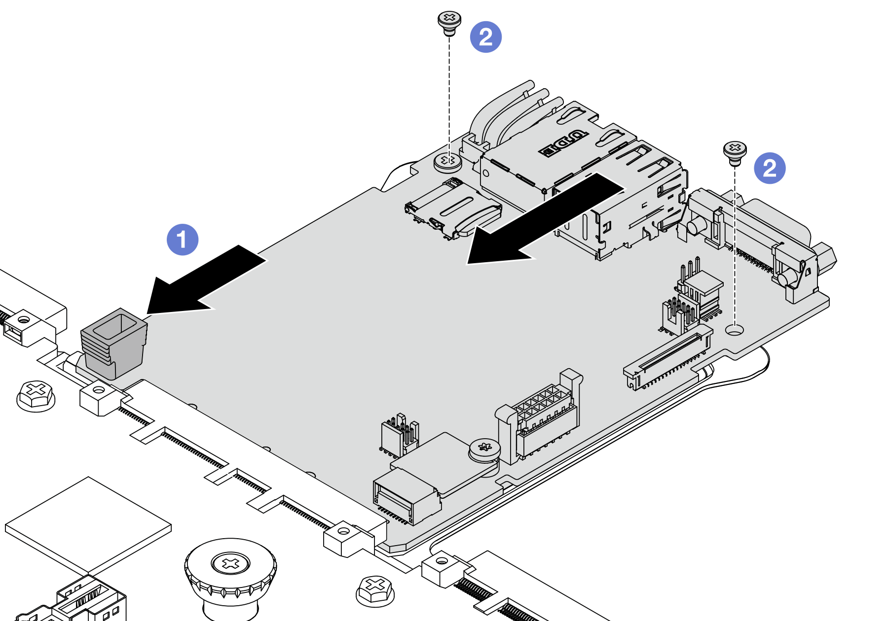
 Align the contacts on the system I/O board with the slots on the processor board, and use both hands to push the system I/O board and slightly insert it into the connector.NoteTo prevent the contacts of the system I/O board from damage, ensure that the system I/O board is aligned correctly with the connector on the processor board, and remains as horizontal as possible during the insertion.
 Install the screws to fix the system I/O board into place.
- Install the system board assembly to the server.Figure 2. System board assembly installation
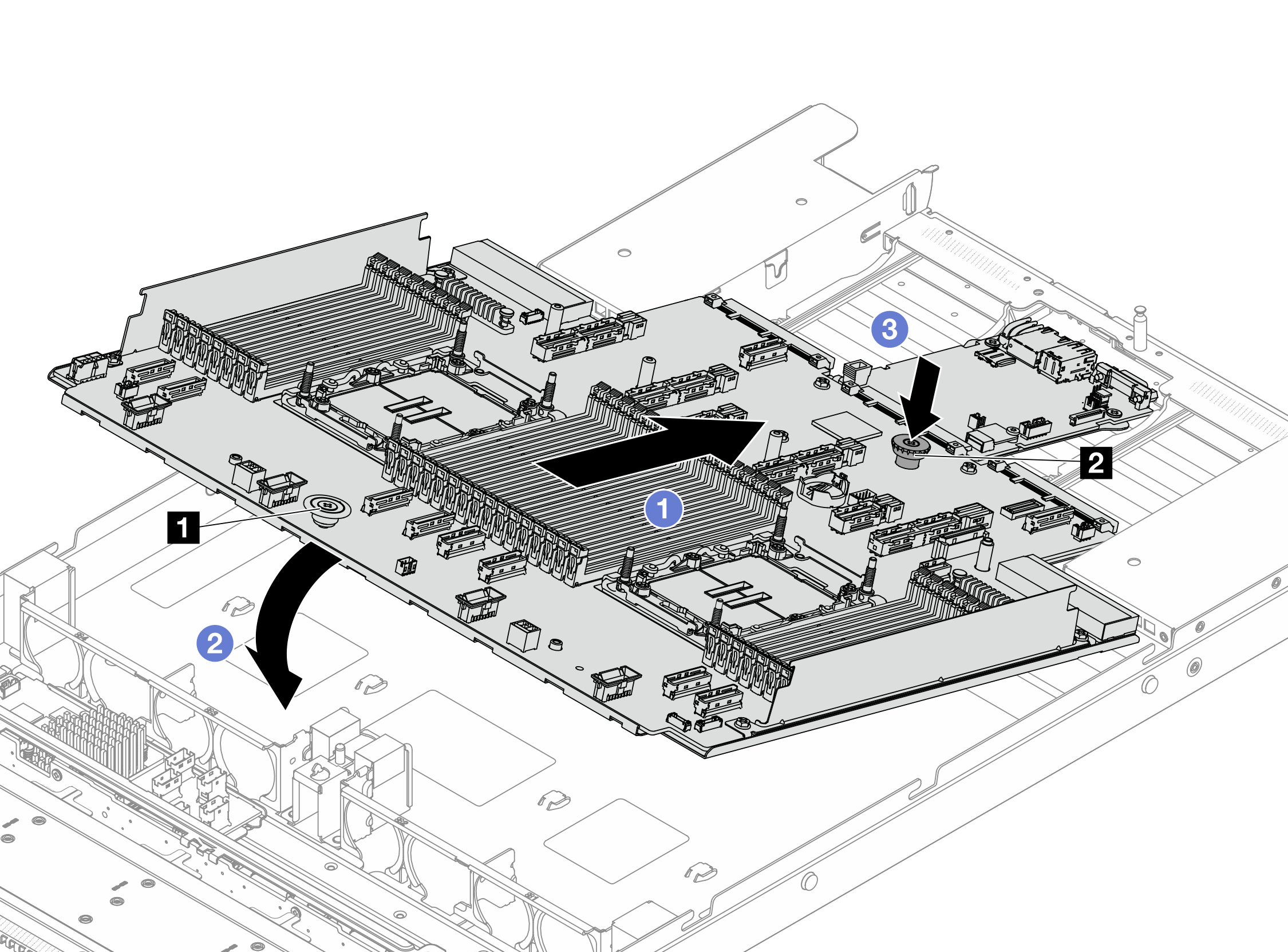
- Hold the release pins 1 and 2 at the same time and lift the system board assembly up.
- Lower the system board assembly into the chassis as illustrated above.
 Slide the system board assembly to the rear of the server until the system board assembly snaps into position. Ensure that:
The rear connectors on the new system board assembly are inserted into the corresponding holes in the rear panel.
The release pin 2 secures the system board assembly in place.
After you finish
- Install any components that you have removed before the removal of system I/O board.
Push the power supply units in place. Ensure that they are connected to the system board assembly.
Reconnect all the required cables to the same connectors on the system board assembly. See Internal cable routing.
Ensure that all components have been reassembled correctly and that no tools or loose screws are left inside the server.
Reinstall the top cover. See Install the top cover.
If the sever was installed in a rack, reinstall the server into the rack. See Server replacement.
Reconnect external cables and power cords to the server.
AttentionTo avoid component damage, connect the power cords last.Power on the server and any peripheral devices. See Power on the server.
Update the UEFI firmware. (Lenovo service technicians only) See Procedure for replacing System I/O board (DC-SCM) and updating system firmware on V4 system..
Update the XCC/LXPM/FPGA SCM/LXUM firmware. See Update the firmware
Perform OneCLI commands or XCC actions to restore the UEFI and XCC settings. See OneCLI commands that restore configuration settings or Using XCC to restore the BMC configuration.
Set the TPM policy. See Enable TPM.
Re-install the FoD key.
Demo video