Remove the system I/O board or processor board
Follow instructions in this section to remove the system I/O board or processor board.
About this task
This task must be operated by trained technicians that are certified by Lenovo Service. Do not attempt to remove or install the part without proper training and qualification.
When removing the memory modules, label the slot number on each memory module, remove all the memory modules from the processor board, and set them aside on a static-protective surface for reinstallation.
When disconnecting cables, make a list of each cable and record the connectors the cable is connected to, and use the record as a cabling checklist after installing the new system board assembly.
Read Installation Guidelines and Safety inspection checklist to ensure that you work safely.
Power off the server and peripheral devices and disconnect the power cords and all external cables. See Power off the server.
Prevent exposure to static electricity, which might lead to system halt and loss of data, by keeping static-sensitive components in their static-protective packages until installation, and handling these devices with an electrostatic-discharge wrist strap or other grounding system.

The heat sinks and processors might be very hot. Turn off the server and wait several minutes to let the server cool before removing the server cover.
Procedure
- Remove the system board assembly.Figure 1. Removing the system board assembly
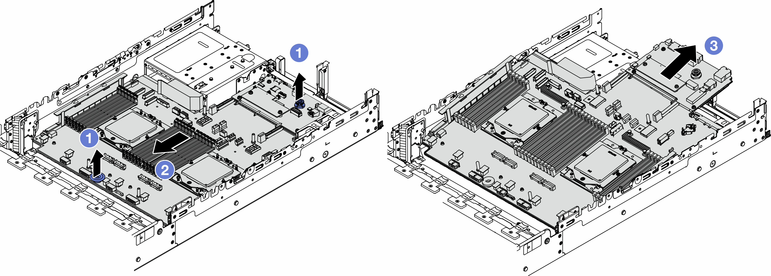
 Lift the two lift handles at the same time.
 Slide the system board assembly towards the front of the chassis until it stops.
 Tilt and lift the system board assembly out of the chassis.
- Separate the system I/O board from the processor board.NoteTo prevent the contact of the system I/O board from damage, pinch and lift the plunger on the system I/O board upward a little and pull out the system I/O board outward. During the entire pulling action, ensure that the system I/O board remains as horizontal as possible.Figure 2. Separating the system I/O board from the processor board
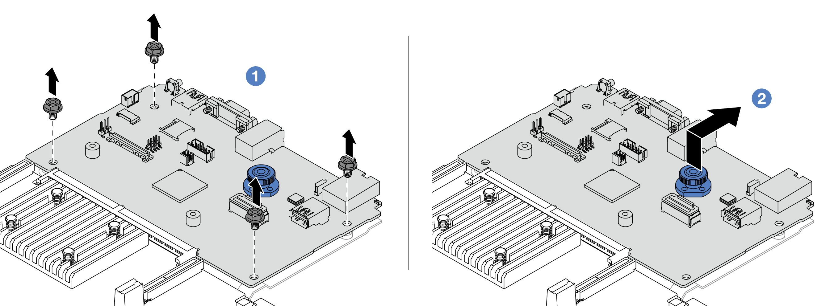
- Remove the screws that secure the system I/O board.
- Lift and hold the rear lift handle and slide the system I/O board towards the rear to disengage it from the processor board.
- (Optional) If you are going to replace the system I/O board, do the following:
Remove the firmware and RoT security module from the system I/O board. See Remove the firmware and RoT security module.
Remove the MicroSD card.
Figure 3. Removing the MicroSD card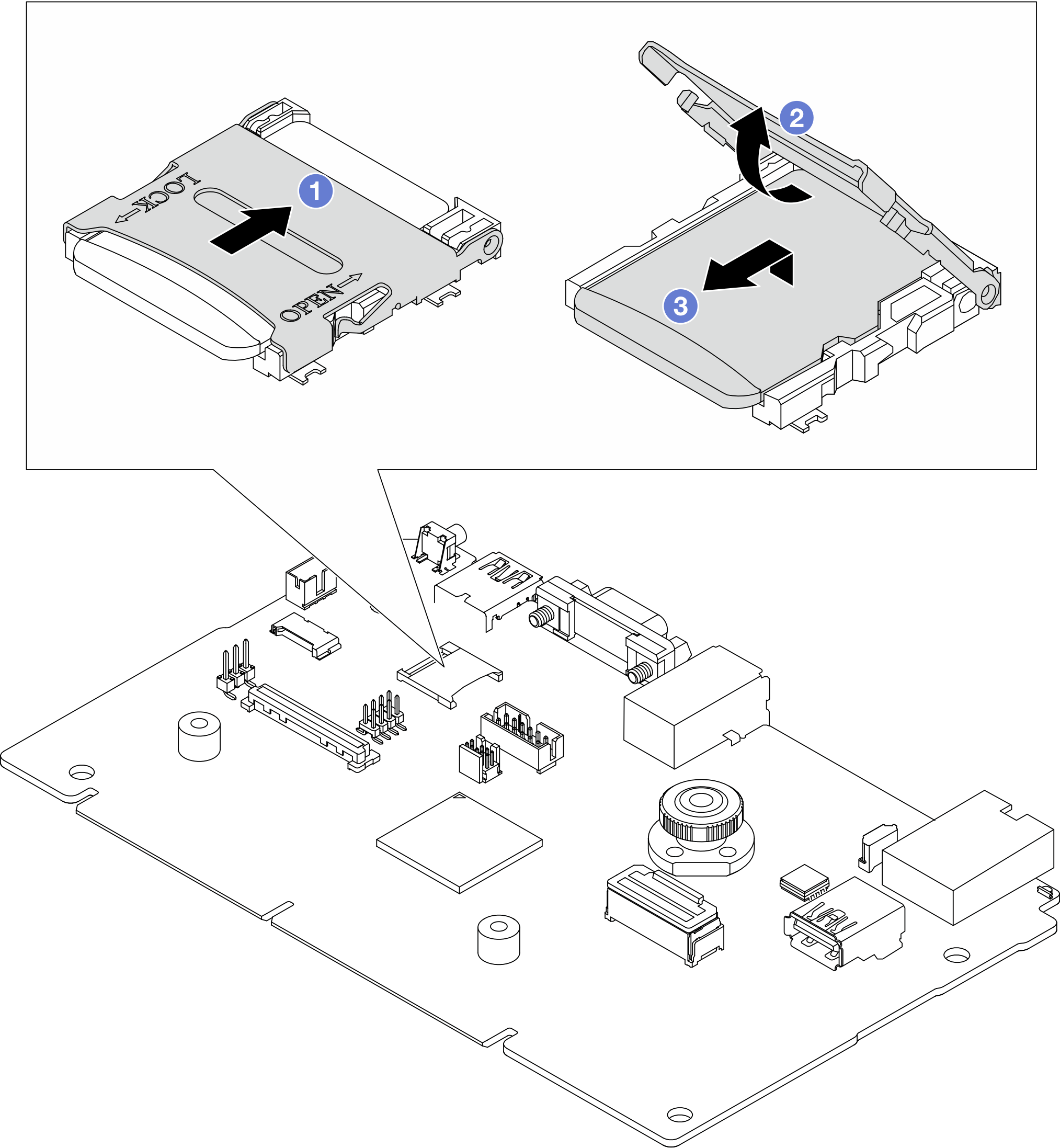
- Slide the socket lid to OPEN direction.
- Flip the socket hinge up.
- Remove the MicroSD card.
After you finish
If you are instructed to return the component or optional device, follow all packaging instructions, and use any packaging materials for shipping that are supplied to you.
ImportantBefore you return the processor board, make sure that you install the processor socket covers from the new processor board. To replace a processor socket cover:Slide the cover out from the processor socket of the new processor board.
Install the cover on the processor socket of the removed processor board.
If you plan to recycle the component, see Disassemble the system board assembly for recycle.
Demo video