Install a 2.5-inch drive backplane
Follow instruction in this section to install a 2.5-inch drive backplane.
About this task
Read Installation Guidelines and Safety inspection checklist to ensure that you work safely.
Power off the server and peripheral devices and disconnect the power cords and all external cables. See Power off the server.
Prevent exposure to static electricity, which might lead to system halt and loss of data, by keeping static-sensitive components in their static-protective packages until installation, and handling these devices with an electrostatic-discharge wrist strap or other grounding system.
Follow the backplane installation rules and order in Drive backplane installation rules and order.
Go to Drivers and Software download website for ThinkSystem SR860 V4 to see the latest firmware and driver updates for your server.
Go to Update the firmware for more information on firmware updating tools.
Procedure
- If necessary, remove the two screws from the backplane carrier.Figure 1. Spare screws on backplane carrier (2.5-inch bay chassis)
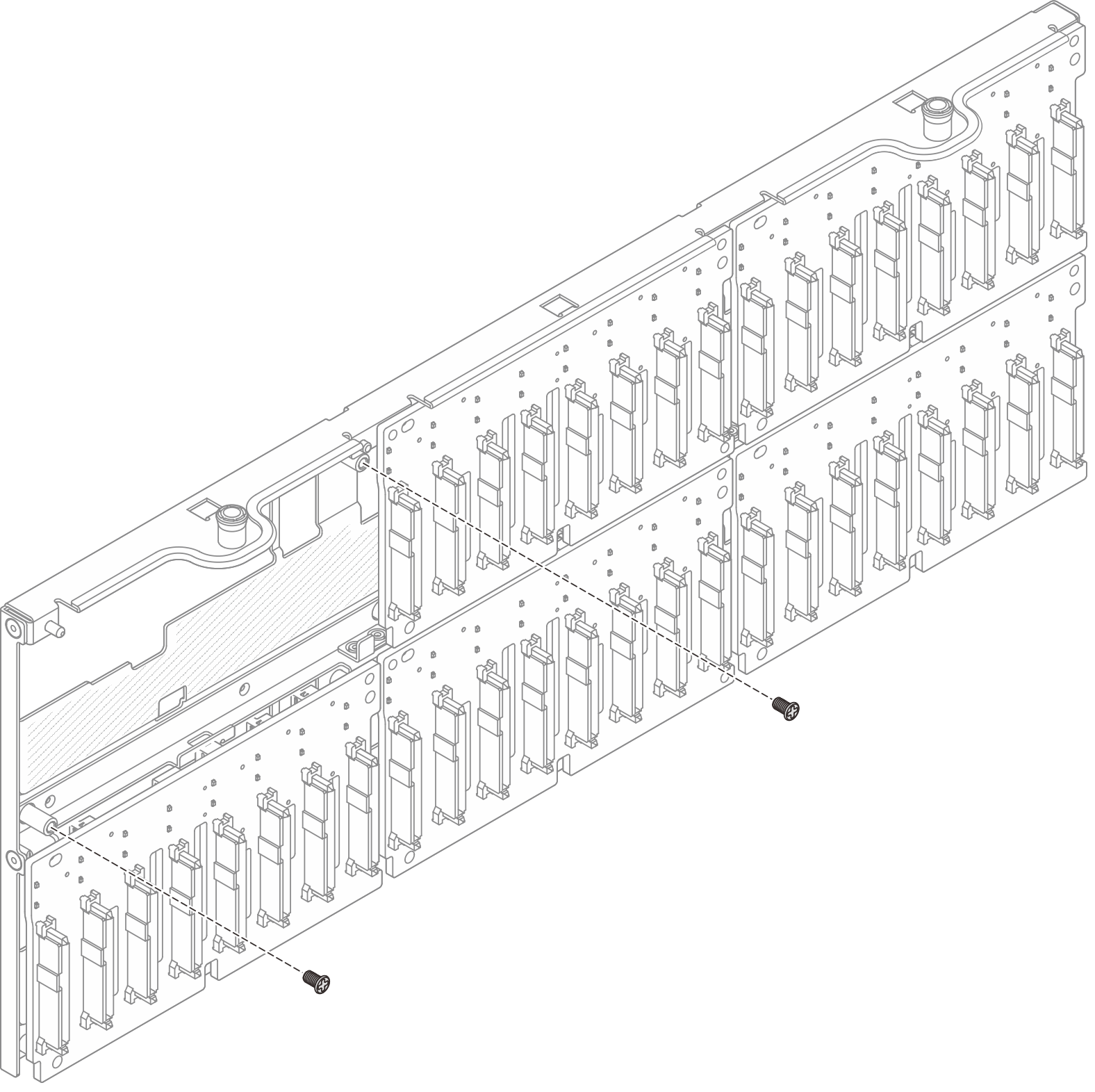 Figure 2. Spare screws on backplane carrier (E3.S bay chassis)
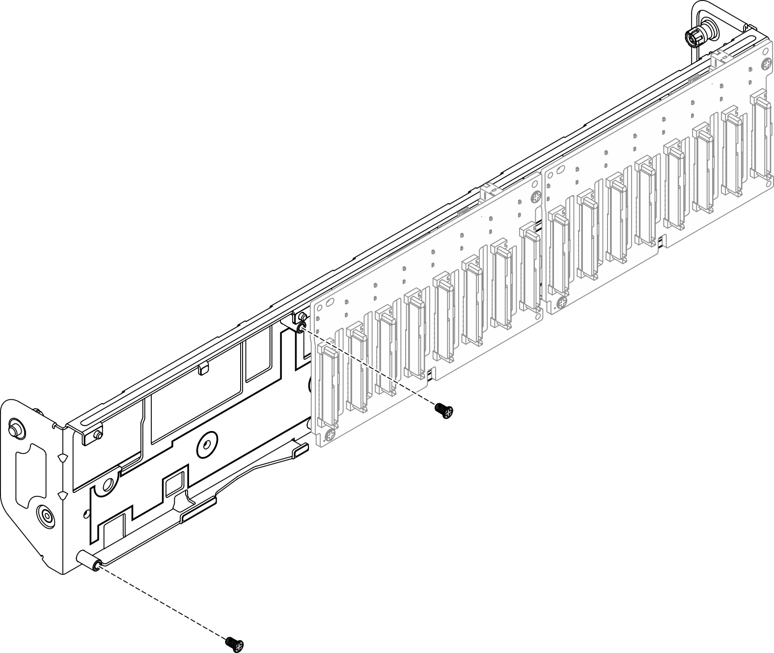
- Install backplane to carrier and secure with two screws.Figure 3. Installing backplane to carrier (2.5-inch bay chassis)
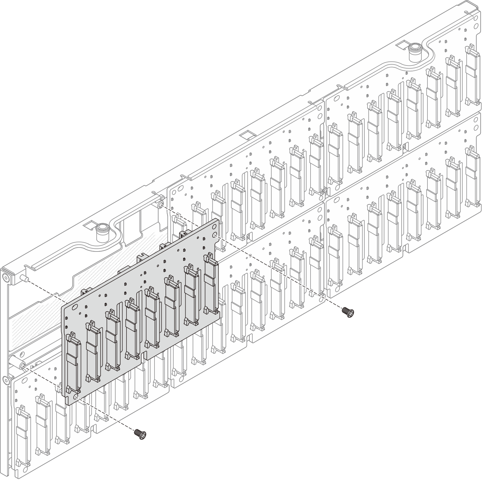 Figure 4. Installing backplane to carrier (E3.S bay chassis)
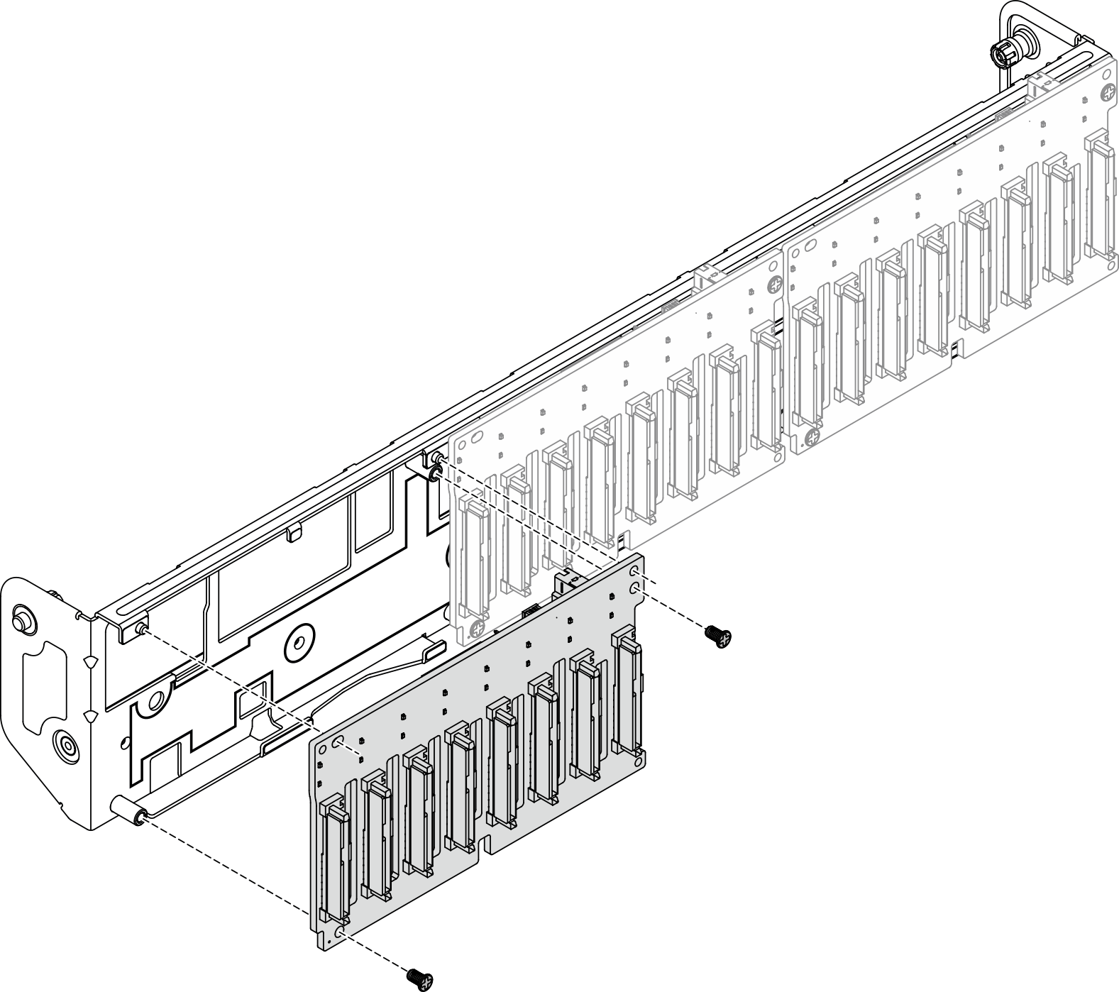
- Install the drive backplane carrier assembly.Figure 5. Installing drive backplane carrier assembly (2.5-inch bay chassis)
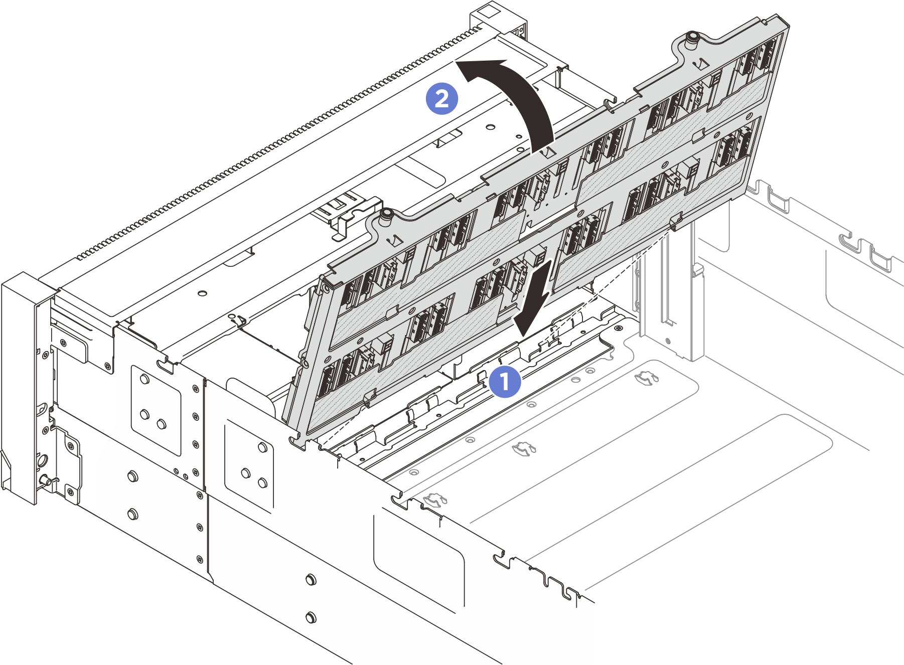 Figure 6. Installing drive backplane carrier assembly (E3.S bay chassis)
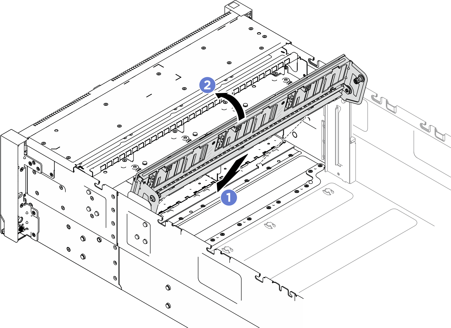
 Align the bottom of the carrier to the slots in the server.
 Pivot the top of the carrier until it clicks into place.
After you finish
Reinstall all the 2.5-inch hot-swap drive and drive fillers. See Install a 2.5-inch hot-swap drive.
Reinstall the fans and the fan cage assembly. See Install a fan and Install the fan cage.
- Reinstall the front air baffle. See Install the front air baffle.
- Reinstall the front top cover. See Install the front top cover.
Complete the parts replacement. See Complete the parts replacement.
If you have installed a 2.5-inch drive backplane with U.3 NVMe drives for Trimode. Enable U.3 x1 mode for the selected drive slots on the backplane through the XCC web GUI. See U.3 NVMe drive can be detected in NVMe connection, but cannot be detected in Tri-mode.
Demo video