Install a 3.5-inch drive backplane
Follow the instructions in this section to install a 3.5-inch drive backplane.
About this task
Read Installation Guidelines and Safety inspection checklist to ensure that you work safely.
Power off the server and disconnect all power cords for this task. See Power off the server.
Prevent exposure to static electricity, which might lead to system halt and loss of data, by keeping static-sensitive components in their static-protective packages until installation, and handling these devices with an electrostatic-discharge wrist strap or other grounding system.
The server supports up to four 3.5-inch hot-swap drive backplanes.
See Technical rules for system fans for detailed information about the storage limitations in different server configurations.
- Before installing a drive backplane:
Determine the location of the backplanes to be installed. Backplanes are installed in the following order:
The installation priority of different backplane types : NVMe > AnyBay > SAS/SATA.
The installation order of SAS/SATA backplanes is Backplane 1 > Backplane 2 > Backplane 3 > Backplane 4, from bottom to top when viewed from the front of the server.
The installation order of NVMe backplanes is Backplane 4 > Backplane 3 > Backplane 2 > Backplane 1, from top to bottom when viewed from the front of the server.
NoteWhen an ODD/tape drive is installed, the first NVMe backplane is to be installed as Backplane 3.
The server supports up to one AnyBay backplane. The location of the AnyBay backplane follows the rules below:
Install the AnyBay backplane to the first available drive cage counted from top when viewed from the front of the server.
When one AnyBay backplane mixes with SAS/SATA backplanes, and there’s no ODD/tape drive installed, install the AnyBay backplane as Backplane 4.
When one AnyBay backplane mixes with SAS/SATA backplanes, and there’s an ODD/tape drive installed, install the AnyBay backplane as Backplane 3.
When one AnyBay backplane mixes with NVMe backplanes, install the NVMe backplanes first, and then install the AnyBay backplane to the first available drive cage counted from top when viewed from the front of the server.
Procedure
- Determine the slot for the backplane to be installed in. See 3.5-inch drive cable routing.
- Install the backplane.
- Slide the backplane as shown until it is seated in position in the drive cage.Figure 1. Installation of a 3.5-inch drive backplane
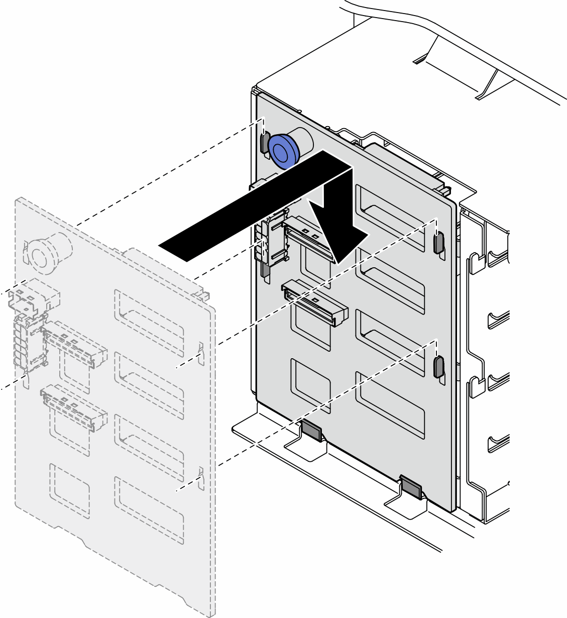
- Slide the backplane as shown until it is seated in position in the drive cage.
After you finish
Connect the cables to the backplane. See 3.5-inch drive cable routing .
Install all the drives and drive bay fillers (if any) into the drive bays. See Install a hot-swap drive.
Reinstall the server cover. See Install a server cover.
Complete the parts replacement. See Complete the parts replacement.
Demo video