Install the Firmware and RoT Security Module
Follow the instructions in this section to install the ThinkSystem V3 Firmware and Root of Trust Security Module (firmware and RoT security module).
About this task
This task must be operated by trained technicians that are certified by Lenovo Service. Do not attempt to remove or install the part without proper training and qualification.
- (Lenovo trained technicians only) After replacing the Firmware and RoT Security Module, update the UEFI, XCC and LXPM firmware to the specific version supported by the server. For detailed information on how to update the firmware, see Tip for replacing a Firmware and RoT Security Module.
Read Installation Guidelines and Safety inspection checklist to ensure that you work safely.
Power off the server and disconnect all power cords for this task. See Power off the server.
Prevent exposure to static electricity, which might lead to system halt and loss of data, by keeping static-sensitive components in their static-protective packages until installation, and handling these devices with an electrostatic-discharge wrist strap or other grounding system.
If the server is in a rack, remove it from the rack.
If foot stands are installed on the server, pivot them inwards and lay the server on its side for easier operation.
Procedure
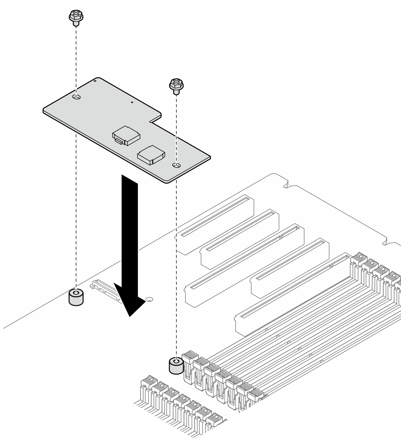
- Place the firmware and RoT security module evenly on the system board; then, align and tighten the two screws with corresponding nuts to secure.Figure 1. Installation of the firmware and RoT security module
After this task is completed
Reinstalled the HL PCIe adapters and FL GPU adapters that were removed for the replacement of the firmware and RoT security module. See Install a HL PCIe adapter and Install a FL GPU adapter.
Reinstalled the A2/L4 GPU air duct that was removed for the replacement of the firmware and RoT security module. See Install an A2/L4 GPU air duct.
Reconnect all the cables that were removed. See Internal cable routing..
Reinstall the air baffle. See Install an air baffle.
Reinstall all the flash power modules, if necessary. See Install a flash power module.
Reinstall the server cover. See Install a server cover.
Complete the parts replacement. See Complete the parts replacement.
Update the UEFI, XCC, and LXPM firmware to the specific version supported by the server. See Tip for replacing a Firmware and RoT Security Module (Lenovo service technicians only).
Perform OneCLI commands or XCC actions to restore the UEFI and XCC settings. See OneCLI commands that restore configuration settings or Using XCC to restore the BMC configuration.
If there is a software (SW) key, for example, XCC FoD key, installed in the system, inject the key again to ensure that the key functions properly. See Using Lenovo Features on Demand.
Set the TPM policy. See Enable TPM.
- Optionally, do the following if needed:
Hide TPM. See Hide/observe TPM.
Update the TPM firmware. See Update the TPM firmware.
Enable UEFI Secure Boot. See Enable UEFI Secure Boot.
Demo video