
Remove the system board (trained technician only)

Follow the instructions in this section to remove a system board.

Important
This task must be operated by trained technicians.

About this task

S002
disconnect all power
CAUTION
The power-control button on the device and the power switch on the power supply do not turn off the electrical current supplied to the device. The device also might have more than one power cord. To remove all electrical current from the device, ensure that all power cords are disconnected from the power source.
Attention

Procedure

  1. Make preparations for this task.
    1. Record all system configuration information, such as Lenovo XClarity Controller IP addresses, vital product data, and the machine type, model number, serial number, Universally Unique Identifier, and asset tag of the server.
    2. Save the system configuration to an external device with Lenovo XClarity Essentials.
    3. Power off the server and disconnect all power cords for this task. See Power off the server.
    4. Prevent exposure to static electricity, which might lead to system halt and loss of data, by keeping static-sensitive components in their static-protective packages until installation, and handling these devices with an electrostatic-discharge wrist strap or other grounding system.
    5. If the server is in a rack, remove it from the rack.
    6. If foot stands are installed on the server, pivot them inwards and lay the server on its side for easier operation.
    7. Remove the server cover. See Remove the server cover.
    8. If necessary, remove all flash power modules. See Remove a flash power module.
    9. Remove the air baffle. See Remove the air baffle.
    10. Disconnect cables for PCIe adapter or full-length GPU adapter.
    11. Remove all the full-length GPU adapters, if any. See Remove a FL GPU adapter.
    12. If necessary, remove the A2/L4 GPU air duct(s) or FL PCIe adapter holder(s) installed on the fan cage. See Remove an A2/L4 GPU air duct or Remove a FL PCIe adapter holder.
    13. Remove all the fan modules and fan filler. See Remove a fan module.
      Attention
      All fan modules must be removed from the fan cage when handling the fan cage assembly.
    14. Remove the fan cage assembly. See Remove the fan cage assembly.
    15. Remove the internal CFF HBA/RAID adapter. See Remove an internal CFF adapter.
    16. Remove the RoT module. See Remove the Firmware and RoT Security Module.
    17. Remove all the PCIe adapters. See Remove a HL PCIe adapter.
    18. Disconnect the intrusion switch cable from the system board, or remove the intrusion switch if necessary. See Remove the intrusion switch.
    19. If necessary, remove the CMOS battery. See Remove the CMOS battery (CR2032).
    20. If necessary, remove the MicroSD card. See Remove the MicroSD card.
    21. Label the slot number on each memory module; then, remove all the memory modules from the system board and set them aside on a static-protective surface for reinstallation. See Remove a memory module.
    22. Remove the processor and the heat sink. See Remove a processor and heat sink (trained technician only).
    23. Make note of where the cables are connected to the system board; then, disconnect all the cables.
      Note
      Disengage all latches, cable clips, release tabs, or locks on cable connectors beforehand. Failing to release them before removing the cables will damage the cable connectors on the system board. Any damage to the cable connectors may require replacing the system board.
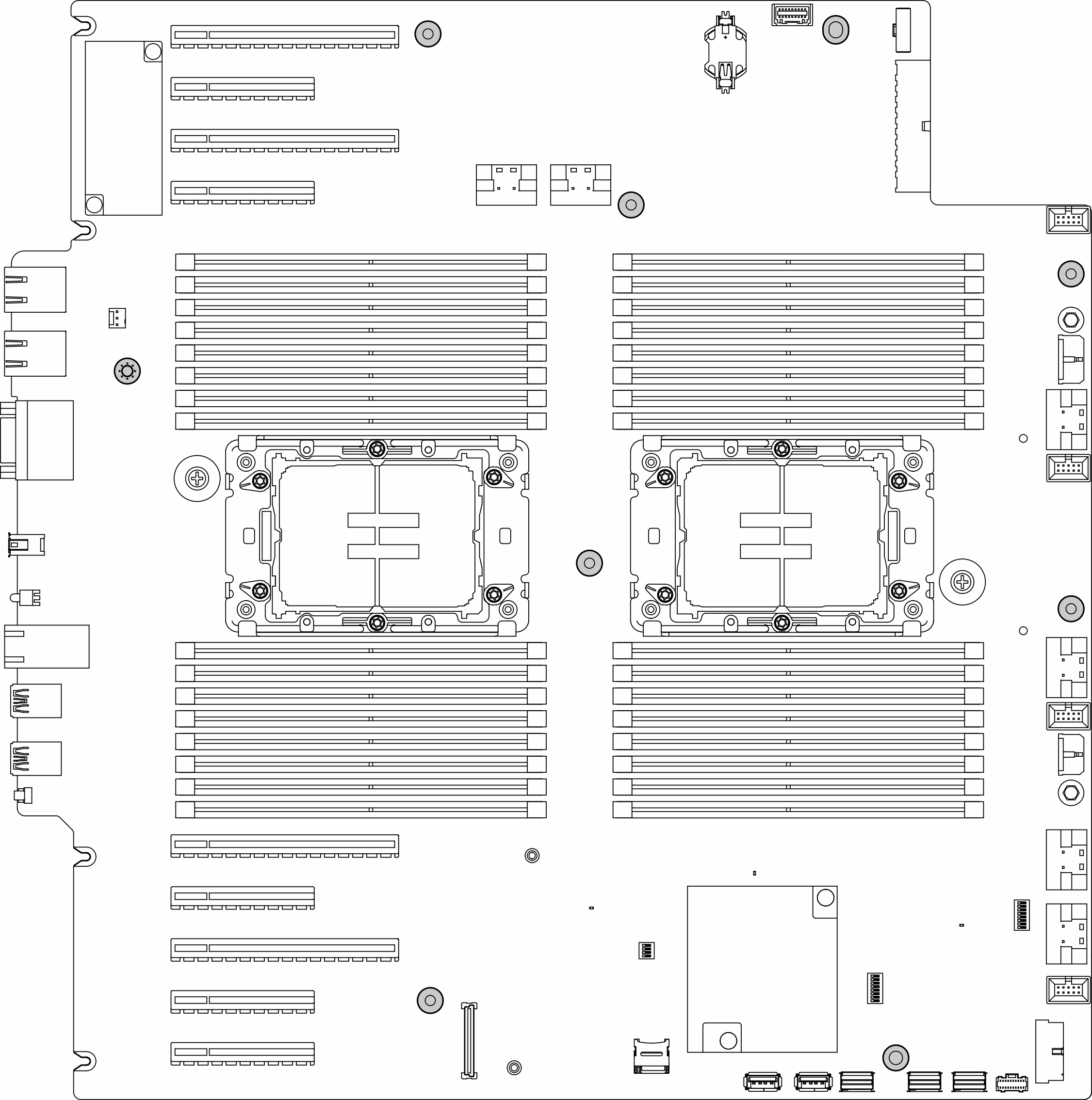
  2. Remove the nine screws that secure the system board.
    Figure 1. Removal of the system board screws
    System board screws removal
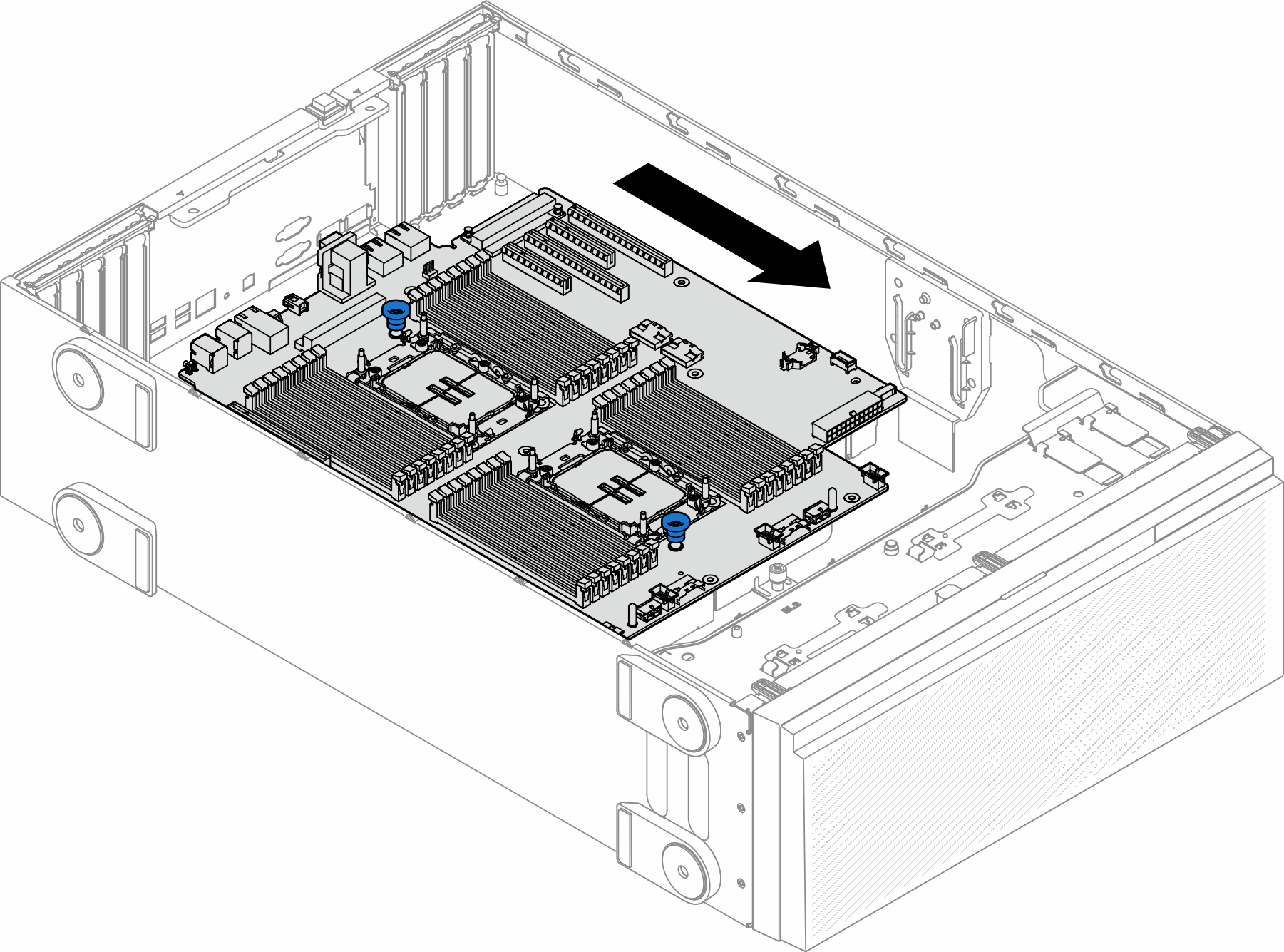
  3. Move the system board towards the front of the server. Make sure that the rear connectors on the system board are disengaged from the corresponding holes in the rear panel.
    Figure 2. Disengaging the system board from chassis
    Disengaging the system board from chassis
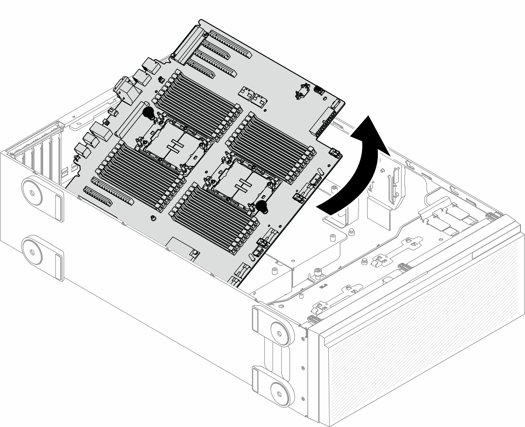
  4. Hold the plungers and remove the system board in the direction as shown.
    Figure 3. Removal of a system board
    System board removal
  5. Place the old system board on a clean, flat, and static-protective surface.

After this task is completed

  • Install a system board. See Install a system board (trained technician only).

  • If you are instructed to return the component or optional device, follow all packaging instructions, and use any packaging materials for shipping that are supplied to you.

Important
Before returning the system board, make sure that you install the processor socket dust covers from the new system board. To replace a processor socket dust cover:
  1. Take a dust cover from the processor socket assembly on the new system board and orient it correctly above the processor socket assembly on the removed system board.

  2. Gently press down the dust cover legs to the processor socket assembly, pressing on the edges to avoid damage to the socket pins. You might hear a click on the dust cover is securely attached.

  3. Make sure that the dust cover is securely attached to the processor socket assembly.