Install the processor board
Follow the instructions in this section to install the processor board.
About this task
A processor board provides different connectors or slots to connect different components or peripherals of the system for communication. The board and the supporting metal sheet constitute a base for the system board assembly. If the processor board fails, it must be replaced.
This task must be operated by trained technicians that are certified by Lenovo Service. Do not attempt to remove or install it without proper training and qualification.
Read Installation Guidelines and Safety inspection checklist to ensure that you work safely.
Power off the server and peripheral devices and disconnect the power cords and all external cables. See Power off the server.
Keep static-sensitive parts in their static-protective packages until installation to prevent exposure to static electricity. Handle the parts with an electrostatic-discharge wrist strap or other grounding systems. Place the parts on a static-protective surface.
Go to Drivers and Software download website for ThinkSystem SR630 V4 to see the latest firmware and driver updates for your server.
Go to Update the firmware for more information on firmware updating tools.
Procedure
- Install the system board assembly to the server.Figure 1. System board assembly installation
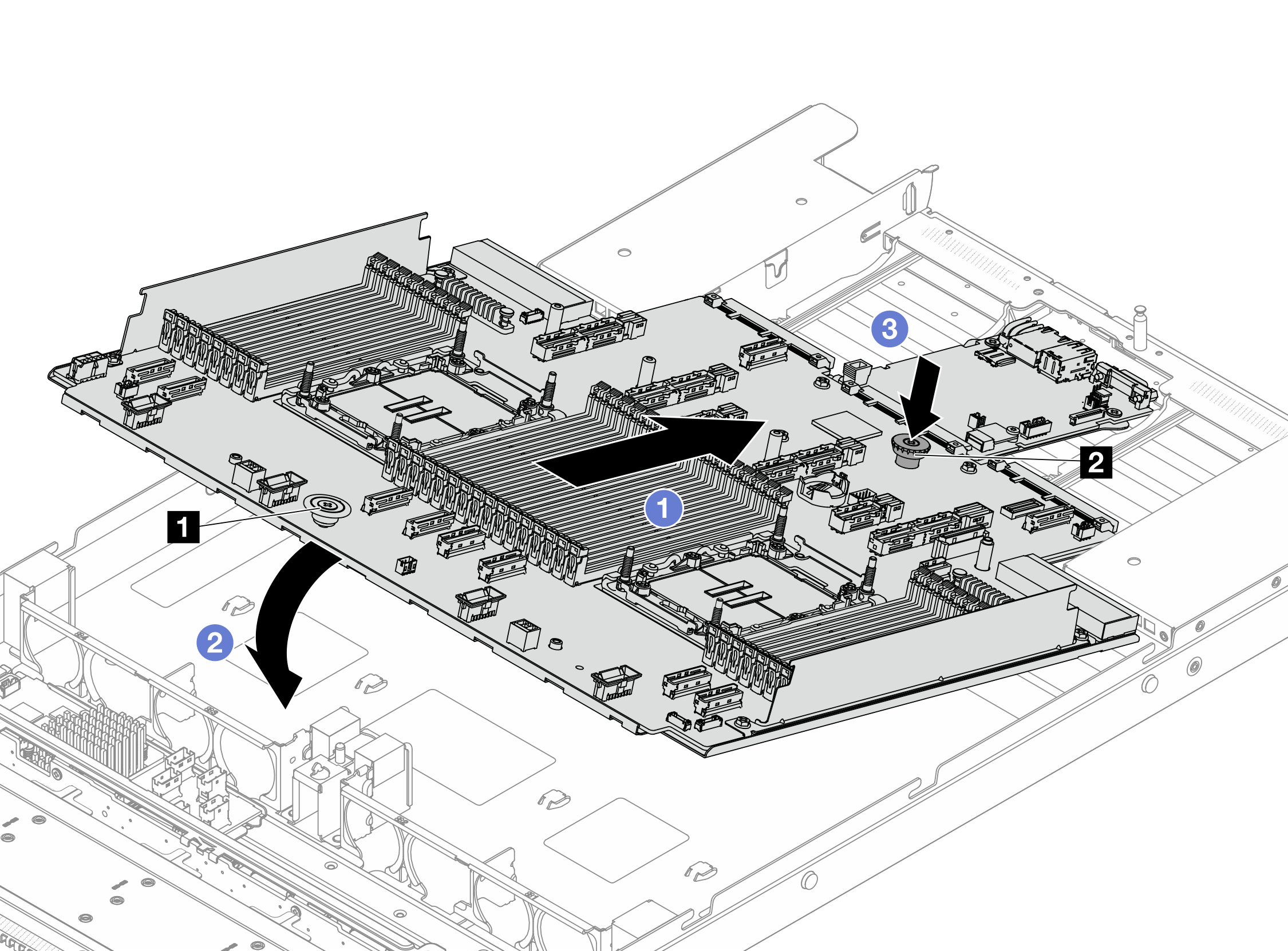
 Hold the release pins 1 and 2 at the same time and lift the system board assembly up.
 Lower the system board assembly into the chassis as illustrated above.
 Slide the system board assembly to the rear of the server until the system board assembly snaps into position. Ensure that:
The rear connectors on the new system board assembly are inserted into the corresponding holes in the rear panel.
The release pin 2 secures the system board assembly in place.
After you finish
- Install any components that you have removed from the failing system board assembly.
Properly route and secure the cables in the server. Refer to detailed cable routing information for each component in Internal cable routing.
Install the air baffle if you have removed it. See Install the air baffle.
Install the top cover. See Install the top cover.
Push the power supplies into the bays until they click into place.
Connect power cords to the server and turn on the server.
Update the FPGA HPM firmware. See Update the firmware
Update the Vital Product Data (VPD) of the system board assembly. See Update the Vital Product Data (VPD). Machine type number and serial number can be found on the ID label, see Identify the server and access the Lenovo XClarity Controller.
Demo video