Install the H100/H200 GPU complex
Follow instructions in this section to install the H100/H200 GPU complex. The procedure must be executed by a trained technician.
About this task
S036
 |  |
| 18 - 32 kg (39 - 70 lb) | 32 - 55 kg (70 - 121 lb) |
CAUTION
Use safe practices when lifting.
Attention
- Read Installation Guidelines and Safety inspection checklist to ensure that you work safely.
- Touch the static-protective package that contains the component to any unpainted metal surface on the server; then, remove it from the package and place it on a static-protective surface.
Note
Make sure you have the required tools listed below available to properly replace the component:
- Torx T10 head screwdriver
- Torx T15 head screwdriver
- Phillips #1 head screwdriver
- Phillips #2 head screwdriver
- Flat head screwdriver
- Alcohol cleaning pad
- 2 x H100/H200 PCM Kit
- 2 x SR780a V3 H100/H200 water loop putty pad kit
- SR780a V3 H100/H200 water loop service kit
- H100/H200 GPU service fixture kit
- H100/H200 NVSwitch PCM kit
- H100/H200 NVSwitch putty pad kit
- H100/H200 GPU baseboard handle kit
- Torx T25 150mm extension bit (for GPU baseboard handles)
Note
Make sure you have the required tools listed below available to properly replace the component:
- Torque screwdriver which can be set to 0.6 newton-meters, 5.3 inch-pounds
Firmware and driver download: You might need to update the firmware or driver after replacing a component.
Go to Drivers and Software download website for ThinkSystem SR780a V3 to see the latest firmware and driver updates for your server.
Go to Update the firmware for more information on firmware updating tools.
The following illustration shows the GPU numbering and corresponding slot numbering in XCC.
Figure 1. GPU numbering
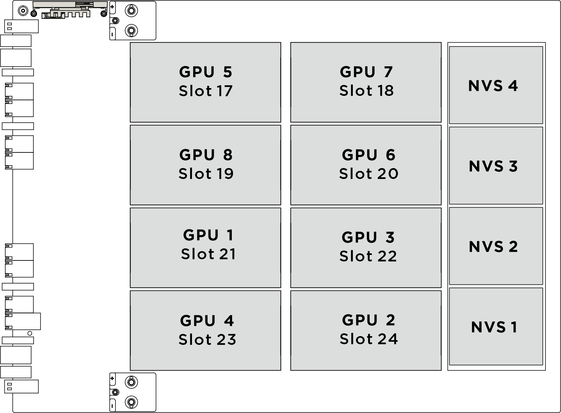
| Physical GPU socket | Slot numbering in XCC | Module ID in nvidia-smi |
|---|---|---|
SXM 1 | Slot 21 | 1 |
SXM 2 | Slot 24 | 2 |
SXM 3 | Slot 22 | 3 |
SXM 4 | Slot 23 | 4 |
SXM 5 | Slot 17 | 5 |
SXM 6 | Slot 20 | 6 |
SXM 7 | Slot 18 | 7 |
SXM 8 | Slot 19 | 8 |
Procedure
- (Optional) Remove the new GPU complex from the package box.
 Extend the two handles on both sides of the GPU baseboard.
 Hold the two handles, and remove the GPU complex out from the package box.
AttentionMake sure two people stand on either side of the GPU complex, and lift it by holding the two handles.Figure 2. Removing the GPU complex from the package box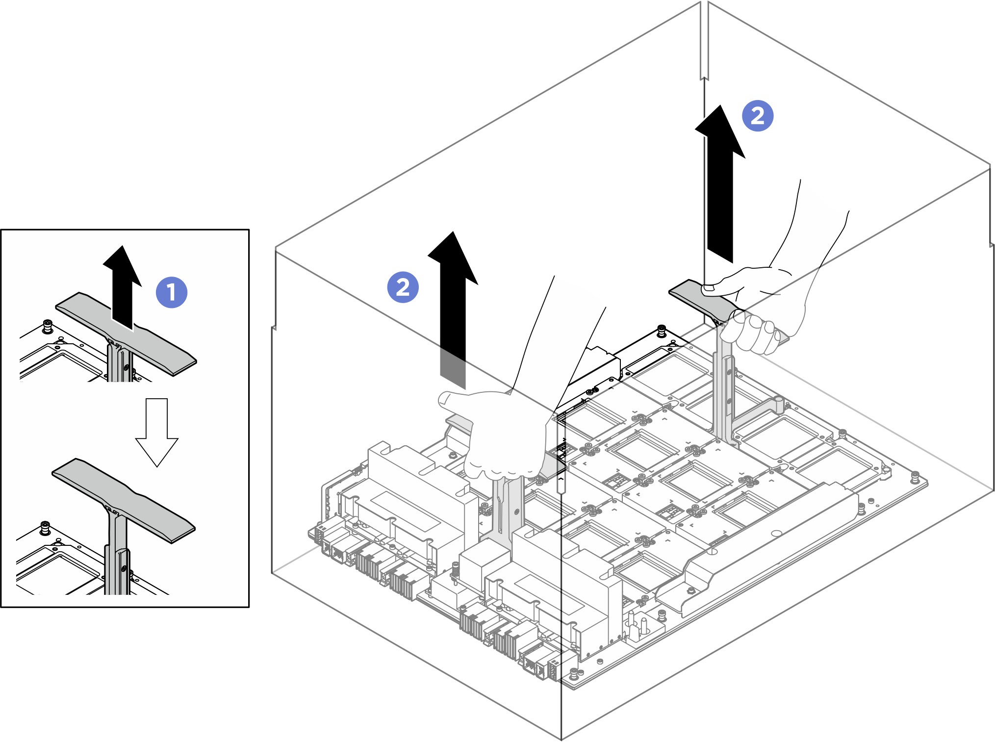
- Install the GPU complex.
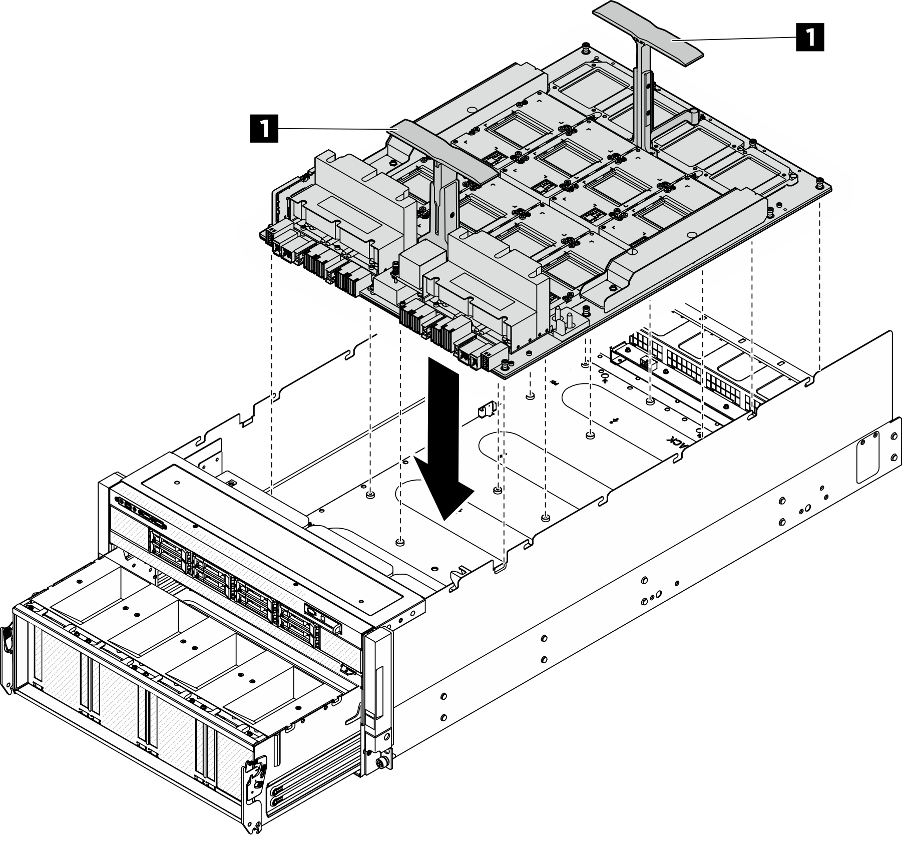
- Hold the handles (1) on both sides of the GPU baseboard in the correct orientation as illustrated; then, align the GPU complex with the seventeen standoffs on the GPU complex adapter plate, and carefully place it onto the adapter plate.AttentionMake sure two people stand on either side of the GPU complex, and lift it by holding the two handles.Figure 3. GPU complex installation
- Press the button on the side of the handle.
 Adjust the handle to create space for screwdriver.Figure 4. Adjusting the handle
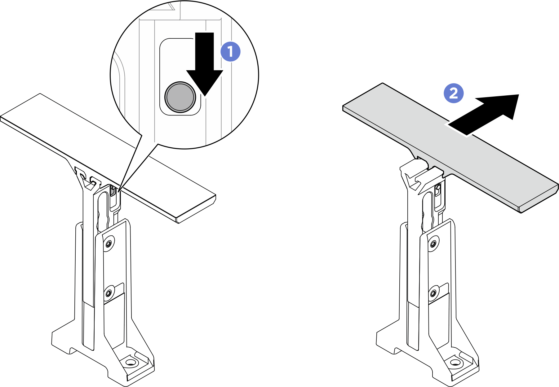
 Unfasten the five M3 screws that secure the handles to the GPU complex; then, remove the handles from the GPU complex.Figure 5. Removing handles
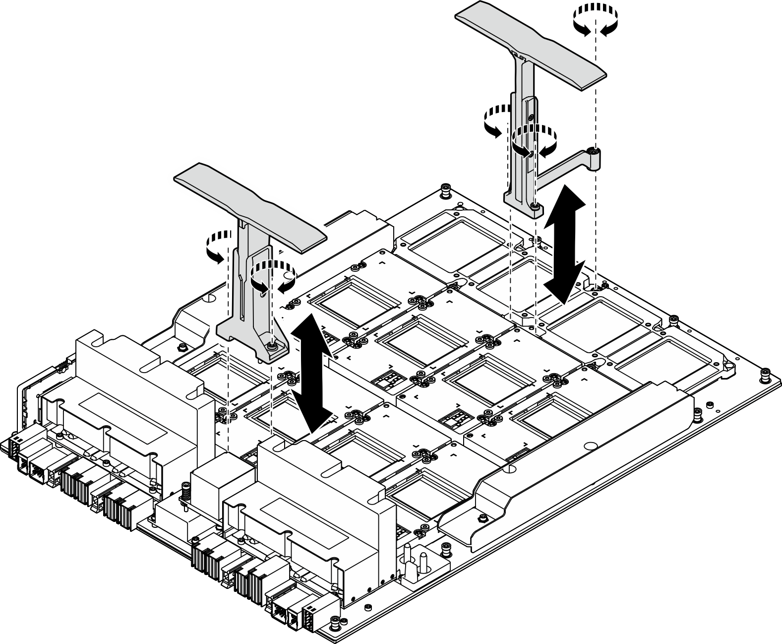
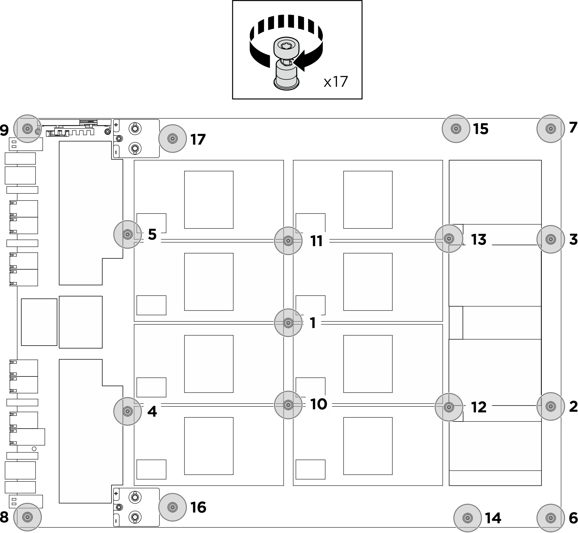
- Follow the sequence shown in the illustration below to fasten the seventeen Torx T15 captive screws to secure the GPU complex.ImportantDo not overtighten the screws to avoid damage.NoteLoosen or tighten the screws with a torque screwdriver set to the proper torque. For reference, the torque required for the screws to be fully loosen or tighten is 0.6±0.024 newton-meters, 5.3±0.212 inch-pounds.Figure 6. Screw installation
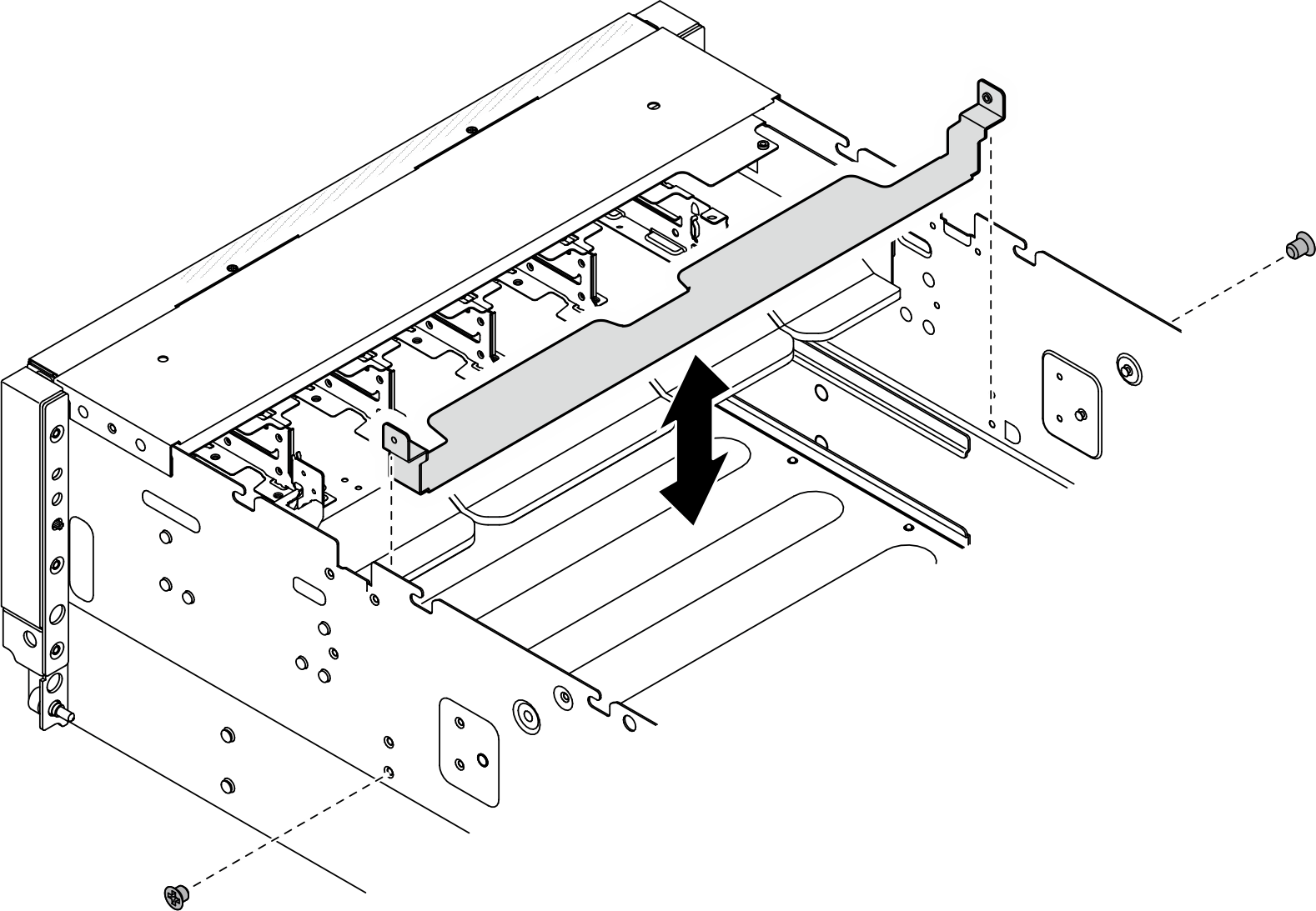
- Align the GPU connector protective bracket with the corresponding screw holes; then, fasten the two M3 screws (PH2, 2 x M3, 0.5 newton-meters, 4.3 inch-pounds) to secure the GPU connector protective bracket to the chassis.Figure 7. Installing GPU connector protective bracket
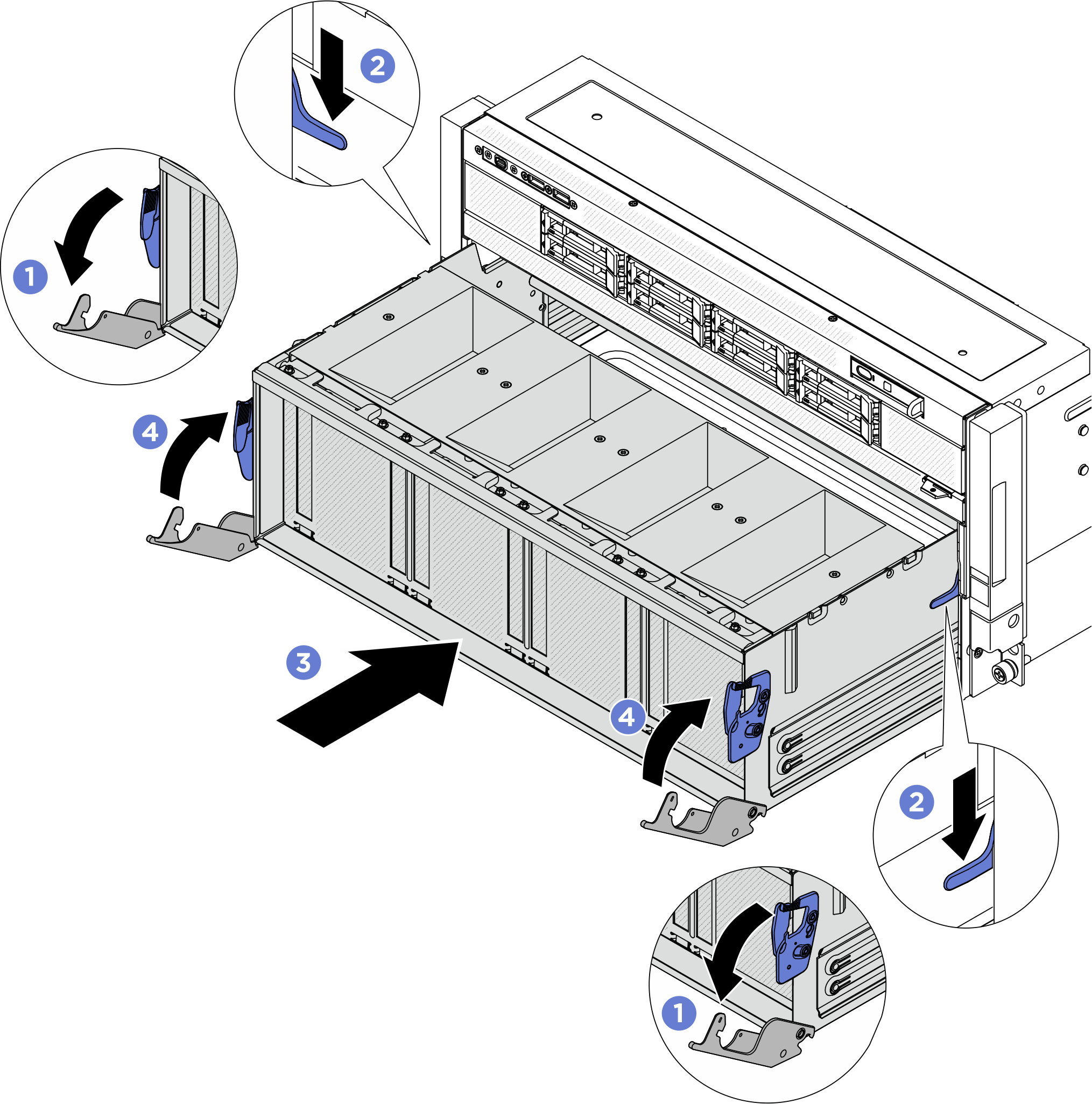
- Install the PCIe switch shuttle.
- Press the two blue release latches.
- Press the two lock latches on both sides of the PCIe switch shuttle.
- Push the PCIe switch shuttle into the chassis until it stops.
- Rotate the two release levers until they lock into place.Figure 8. PCIe switch shuttle installation
After you finish
- Reinstall the NVSwitch cold plate module. See Install the H100/H200 NVSwitch cold plate module.
- Reinstall the front H100/H200 GPU cold plate module. See Install the front H100/H200 GPU cold plate module.
- Reinstall the rear H100/H200 GPU cold plate module. See Install the rear H100/H200 GPU cold plate module.
- Reconnect the cables to the GPU baseboard. See GPU baseboard cable routing for more information.
- Reconnect all the cables that were disconnected. See Internal cable routing.
- Reinstall the power complex. See Install the power complex.
- Reinstall the CPU complex. See Install the CPU complex.
- Reinstall the fan cage. See Install the fan cage (trained technician only).
- Reinstall the rear top cover. See Install the rear top cover.
- Reinstall the front top cover. See Install the front top cover.
- Complete the parts replacement. See Complete the parts replacement.
Give documentation feedback