Install the H100/H200 NVSwitch cold plate module
Follow instructions in this section to install the H100/H200 NVSwitch cold plate module. The procedure must be executed by a trained technician.
About this task
Attention
- Read Installation Guidelines and Safety inspection checklist to ensure that you work safely.
- Touch the static-protective package that contains the component to any unpainted metal surface on the server; then, remove it from the package and place it on a static-protective surface.
- Two people and one lifting device on site that can support up to 400 lb (181 kg) are required to perform this procedure. If you do not already have a lifting device available, Lenovo offers the Genie Lift GL-8 material lift that can be purchased at Data Center Solution Configurator. Make sure to include the Foot-release brake and the Load Platform when ordering the Genie Lift GL-8 material lift.
- A torque screwdriver is available for request if you do not have one at hand.
Note
Make sure you have the required tools listed below available to properly replace the component:
- Torx T15 head screwdriver
- Phillips #1 head screwdriver
- Phillips #2 head screwdriver
- Flat head screwdriver
- Alcohol cleaning pad
- H100/H200 NVSwitch PCM kit
- H100/H200 NVSwitch putty pad kit
Important
Putty pad/phase change material (PCM) replacement guidelines
- Before replacing the putty pad/PCM, gently clean the hardware surface with an alcohol cleaning pad.
- Hold the putty pad/PCM carefully to avoid deformation. Make sure no screw hole or opening is blocked by the putty pad/PCM.
- Do not use expired putty pad/PCM. Check the expiry date on putty pad/PCM package. If the putty pads/PCM are expired, acquire new ones to properly replace them.
The following illustration shows the GPU numbering and corresponding slot numbering in XCC.
Figure 1. GPU numbering
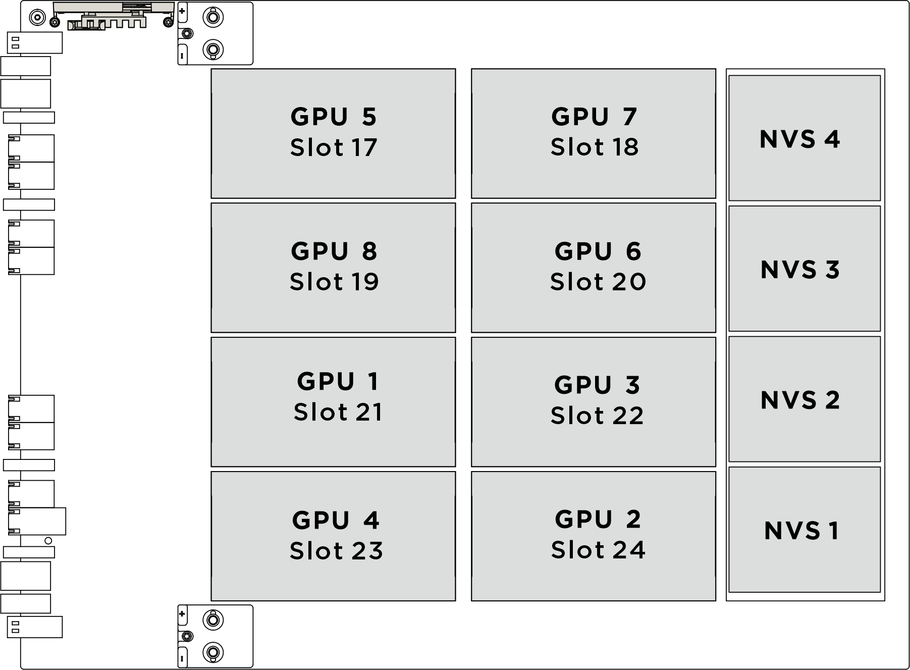
| Physical GPU socket | Slot numbering in XCC | Module ID in nvidia-smi |
|---|---|---|
SXM 1 | Slot 21 | 1 |
SXM 2 | Slot 24 | 2 |
SXM 3 | Slot 22 | 3 |
SXM 4 | Slot 23 | 4 |
SXM 5 | Slot 17 | 5 |
SXM 6 | Slot 20 | 6 |
SXM 7 | Slot 18 | 7 |
SXM 8 | Slot 19 | 8 |
The following illustration shows the components for NVSwitch cold plate module.
Figure 2. NVSwitch cold plate module components identification
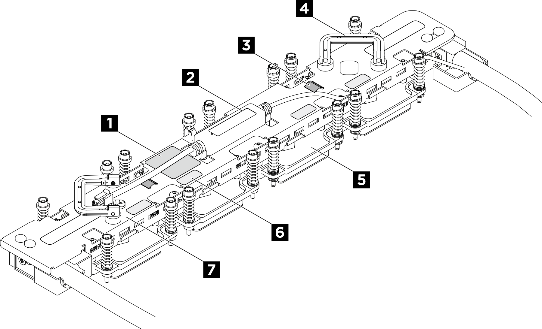
| 1 NVSwitch cold plate torque label | 2 Leakage sensor module |
| 3 Hose tie | 4 Handle |
| 5 NVSwitch cold plate | 6 NVSwitch slot number label |
| 7 Manifold |
Procedure
- Replace the Phase Change Material (PCM) and putty pads on the cold plates.
 Remove the liner from one side of the pad. Align the PCM with the marking (1) on the bottom of the cold plate, and place it onto the cold plate; then, apply finger pressure across the entire surface area of the PCM to remove any trapped air and allow 1-2 minutes dwell time until it is firmly attached. Carefully remove the remaining top liner.
 Remove the liner from one side of the pad. Align the putty pad with the marking (2) on the bottom of the cold plate, and attach it to the cold plate and apply light finger pressure across the entire surface area of the pad to ensure adhesion. Carefully remove the remaining top liner.
- Repeat to replace the PCM and putty pads on the four cold plates.
AttentionPCMcannot be reused.PCMmust bereplacedwith new ones every time the water loop is removed.
After PCM is replaced, there is an expected short duration of throttling before the GPU returns to normal operation. This is due to the PCM requiring a break-in period after being replaced.
- After replacing the GPU PCM and putty pads, servicers must perform the H100/H200 GPU PCM TIM melting procedure to monitor the GPU until the PCM Thermal Interface Material (TIM) has melted. See PCM TIM Melt Procedure for Neptune Water Cooled Servers with Nvidia H100 H200 GPUs (trained technicians only).
Figure 3. PCM and putty pads application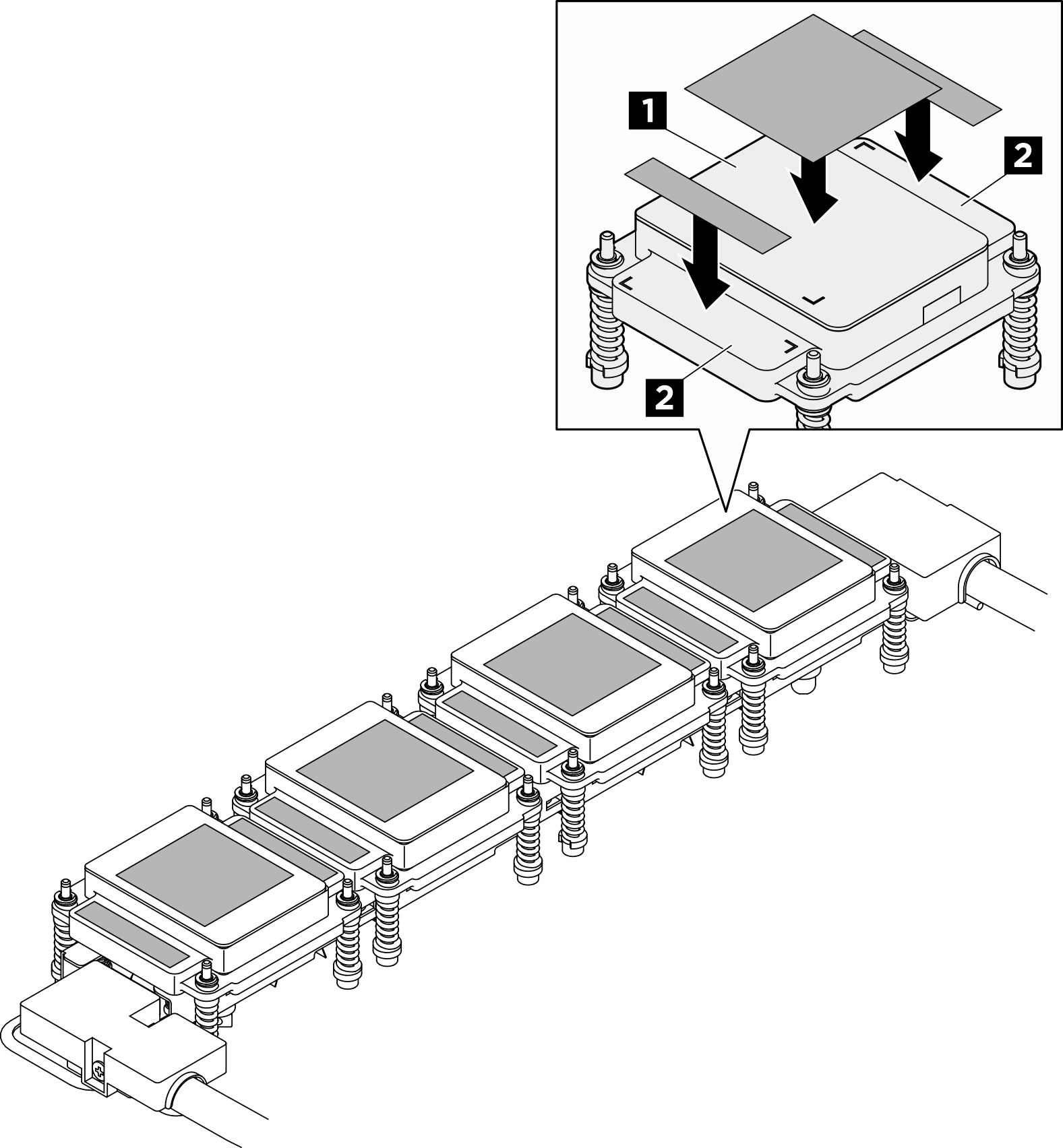
- Install the NVSwitch cold plate module.
- Lift the NVSwitch cold plate module by the handles; then, align the cold plates with the NVSwitches on the GPU baseboard, and gently place it onto the NVSwitches.
- Adjust the cold plates until they are securely seated in the NVSwitch sockets.
Figure 4. Installing the NVSwitch cold plate module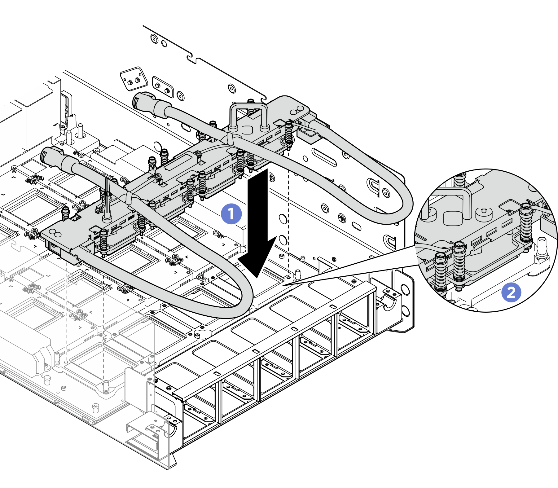
- Follow the screw sequence specified on the cold plate label, and repeat to fully tighten the sixteen Torx T15 screws with a torque screwdriver set to the proper torque.
- Fasten the screws by 720 degrees following the screw installation sequence: → →
 →
→  NoteMake sure to follow screw installation sequence to prevent cold plate tilting.
Figure 5. Repeat to fully tighten all the screws Figure 6. Installing the NVSwitch cold plates
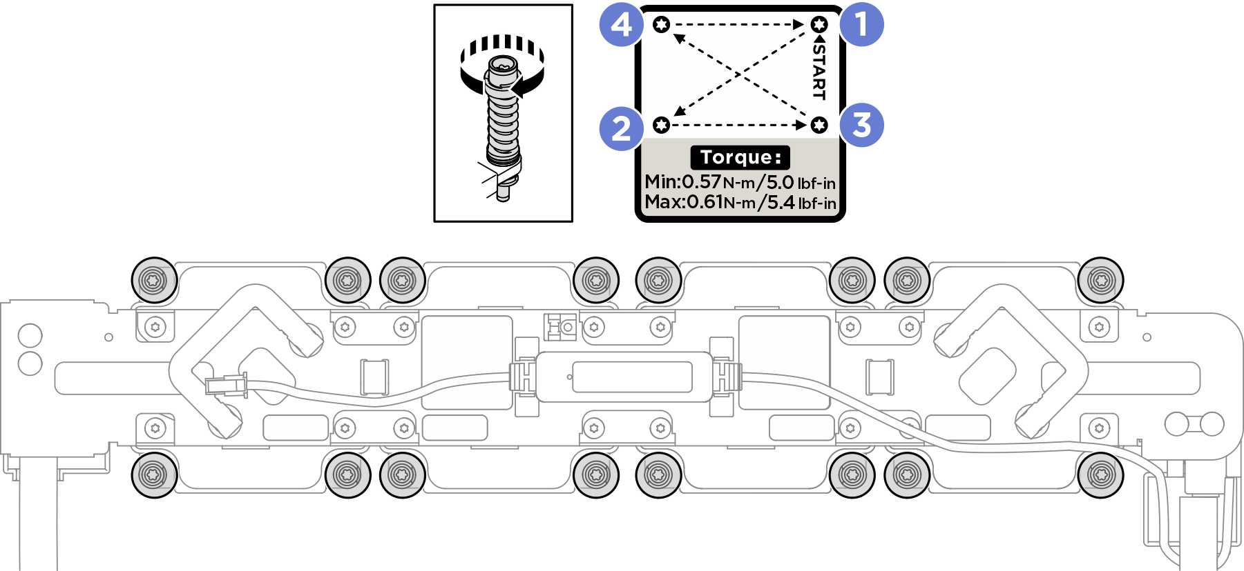
- Fasten the screws by 720 degrees following the screw installation sequence:
- The following illustration shows the hose holder location.Figure 7. Hose holder location
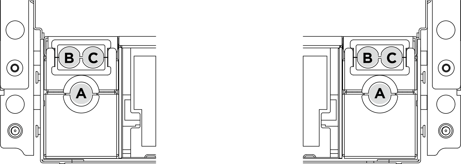
- Place the NVSwitch cold plate module hoses on (1) hose holder A.Important
Check the guiding labels on the hoses and hose holders to ensure they match.
Figure 8. Placing the hoses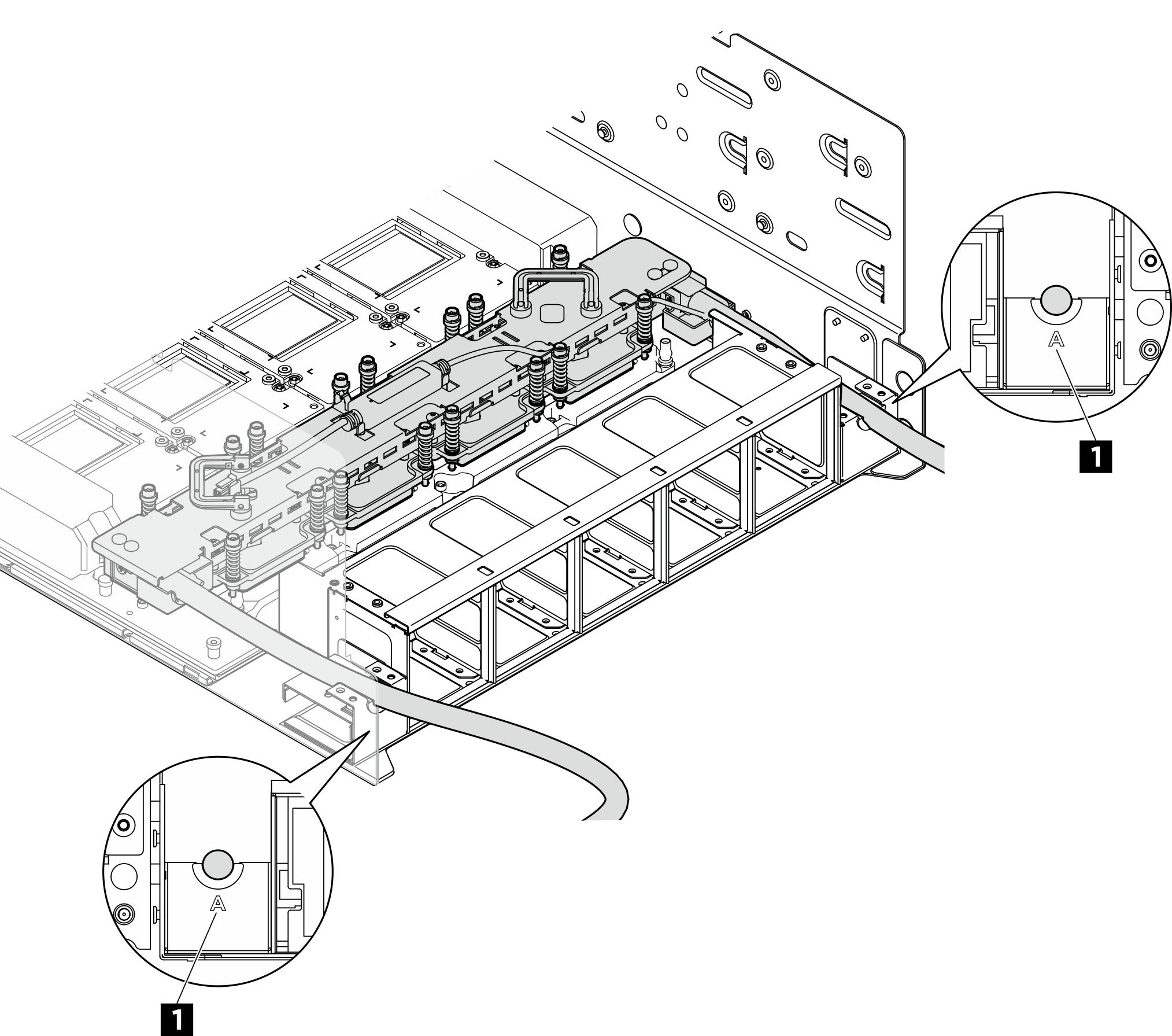
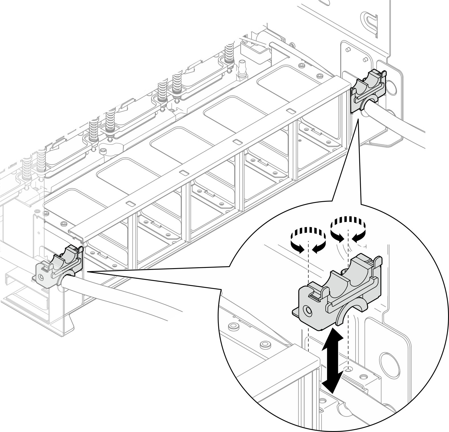
1 Hose holder A - Align the hose holder B/C with the two screw holes on hose holder A; then, fasten the two captive screws (PH1, 2 x M3, 0.5 newton-meters, 4.3 inch-pounds) to secure hose holder B/C on top of hose holder A. Repeat to install hose holder B/C on the other side.Figure 9. Installing hose holder B/C
- Align the hose guide with the screw hole on the NVSwitch manifold and the two screw holes on the chassis; then, fasten the three M3 screws (PH2, 3 x M3, 0.5 newton-meters, 4.3 inch-pounds) to secure the hose guide. Repeat to install the hose guide on the other side.Figure 10. Installing the hose guides
- If front and rear GPU cold plate modules are installed, place the hoses and cables on the hose guides, and secure them with the hose ties. See Fan control board cable routing and Leakage sensor module cable routing.Figure 11. Placing the hoses and cables on the hose guides
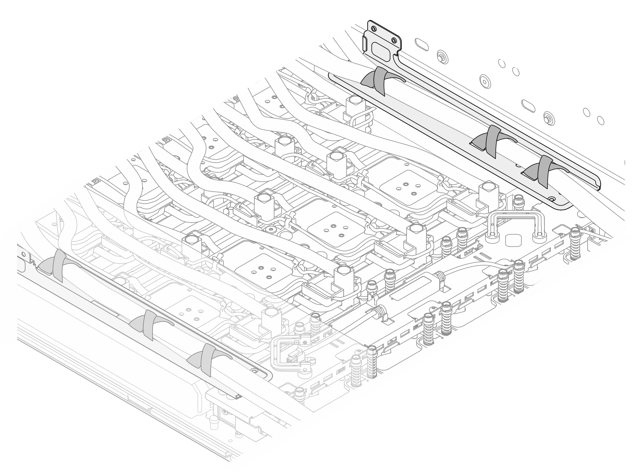
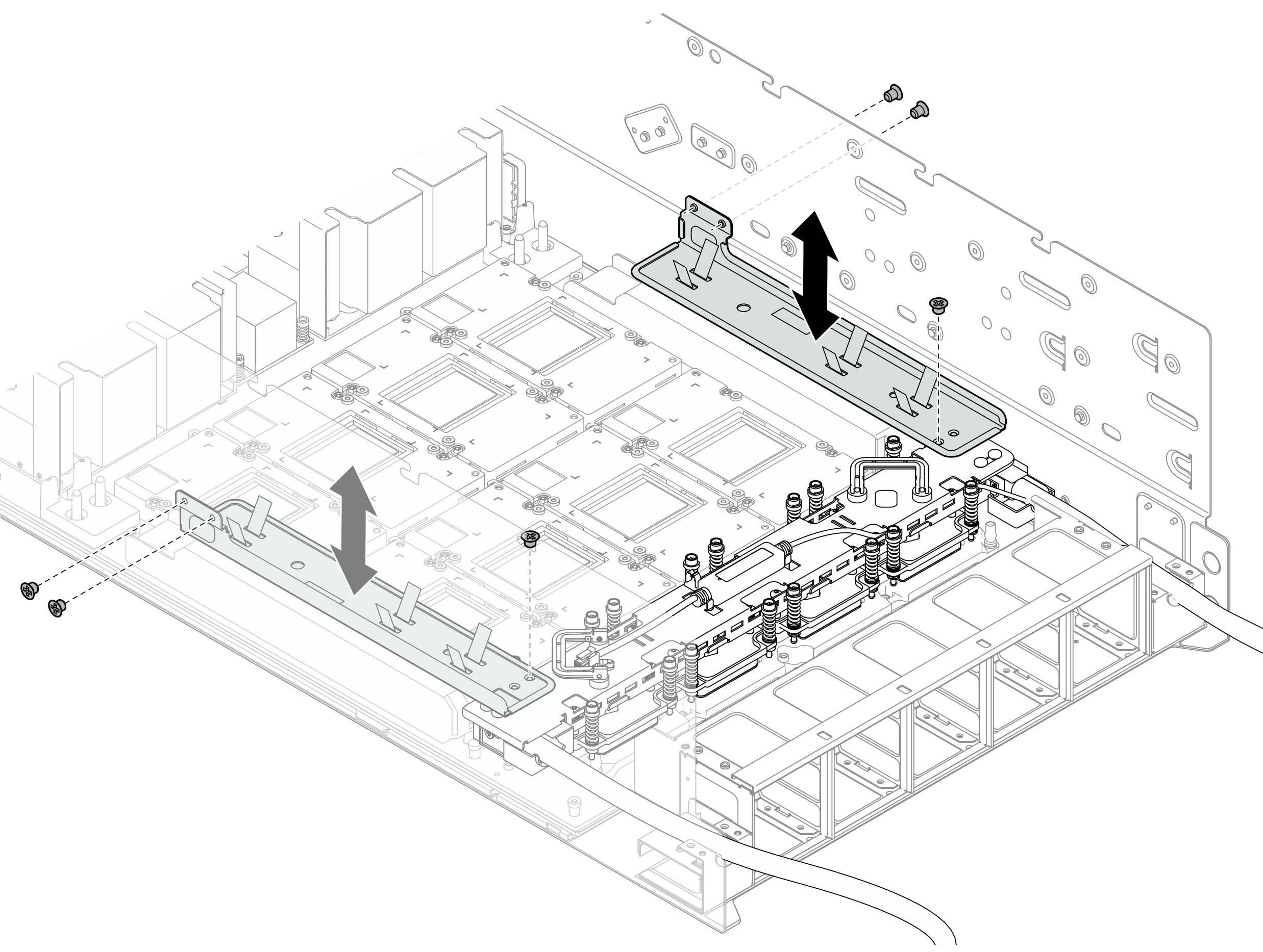
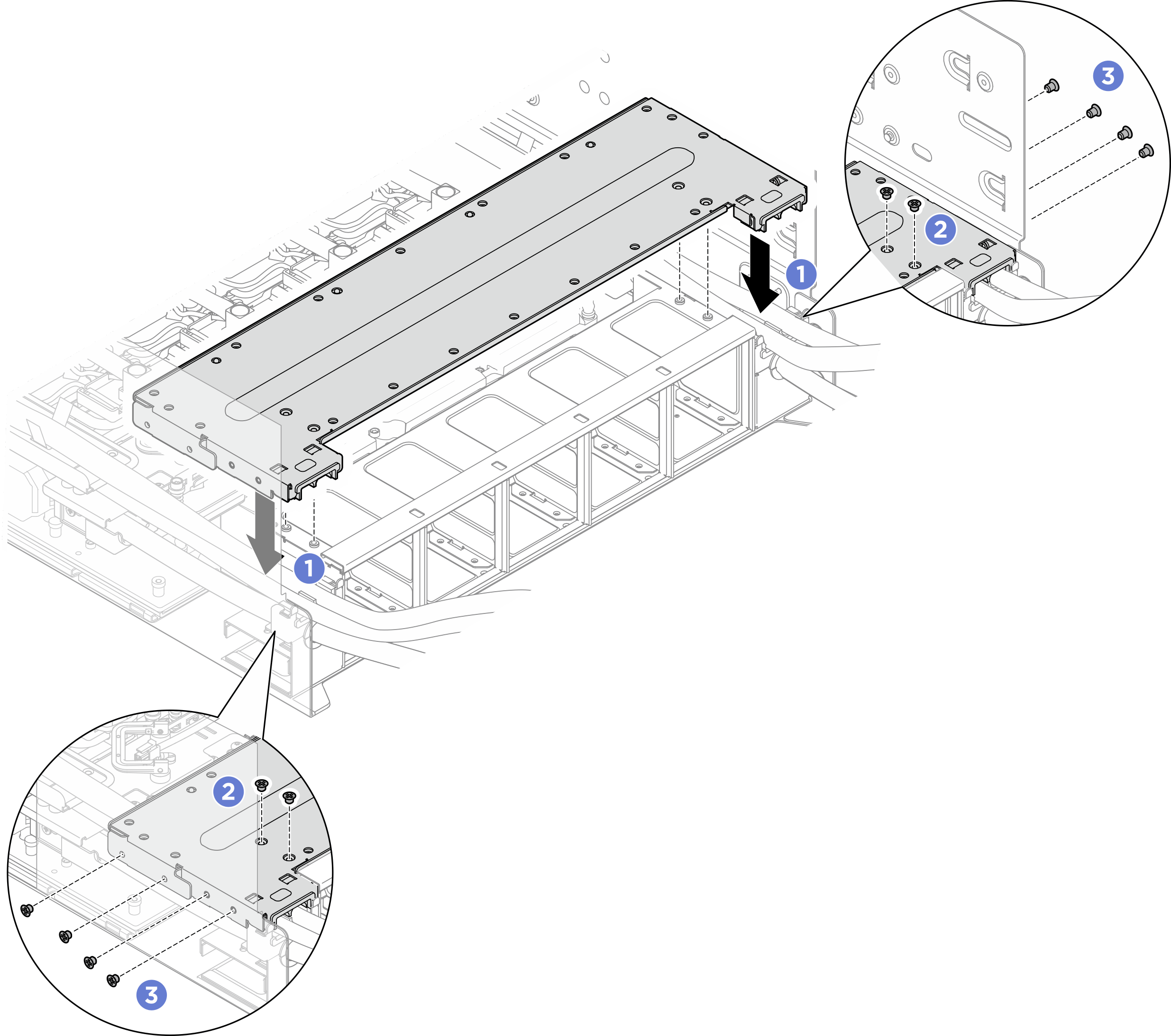
- Install the rear fan cage support bracket.
- Align the rear fan cage support bracket with the corresponding screw holes; then, install the rear fan cage support bracket on top of hose holder B/C as illustrated.
- Fasten the four M3 screws (PH2, 4 x M3, 0.5 newton-meters, 4.3 inch-pounds) to secure the rear fan cage support bracket to the fan cage.
- Fasten the eight M3 screws (PH2, 8 x M3, 0.5 newton-meters, 4.3 inch-pounds) to secure the rear fan cage support bracket to the chassis.Figure 12. Installing the rear fan cage support bracket
After you finish
- Reconnect all the cables that were disconnected. See Internal cable routing.
- Reinstall the power complex. See Install the power complex.
- Reinstall the CPU complex. See Install the CPU complex.
- Reinstall the fan cage. See Install the fan cage (trained technician only).
- Reinstall the rear top cover. See Install the rear top cover.
- Reinstall the front top cover. See Install the front top cover.
- Complete the parts replacement. See Complete the parts replacement.
Give documentation feedback