Install the power complex
Follow instructions in this section to install the power complex. The procedure must be executed by a trained technician.
About this task
Attention
- Read Installation Guidelines and Safety inspection checklist to ensure that you work safely.
- Touch the static-protective package that contains the component to any unpainted metal surface on the server; then, remove it from the package and place it on a static-protective surface.
Procedure
 Align the power complex with the six guide pins on the chassis; then, lower the power complex into the chassis until it is securely engaged.
 Locate the ten screw holes marked with P on both sides of the chassis; then, fasten the ten M3 screws (P1-P5) (PH2, 10 x M3, 0.5 newton-meters, 4.3 inch-pounds) to secure the power complex.Figure 1. Power complex installation
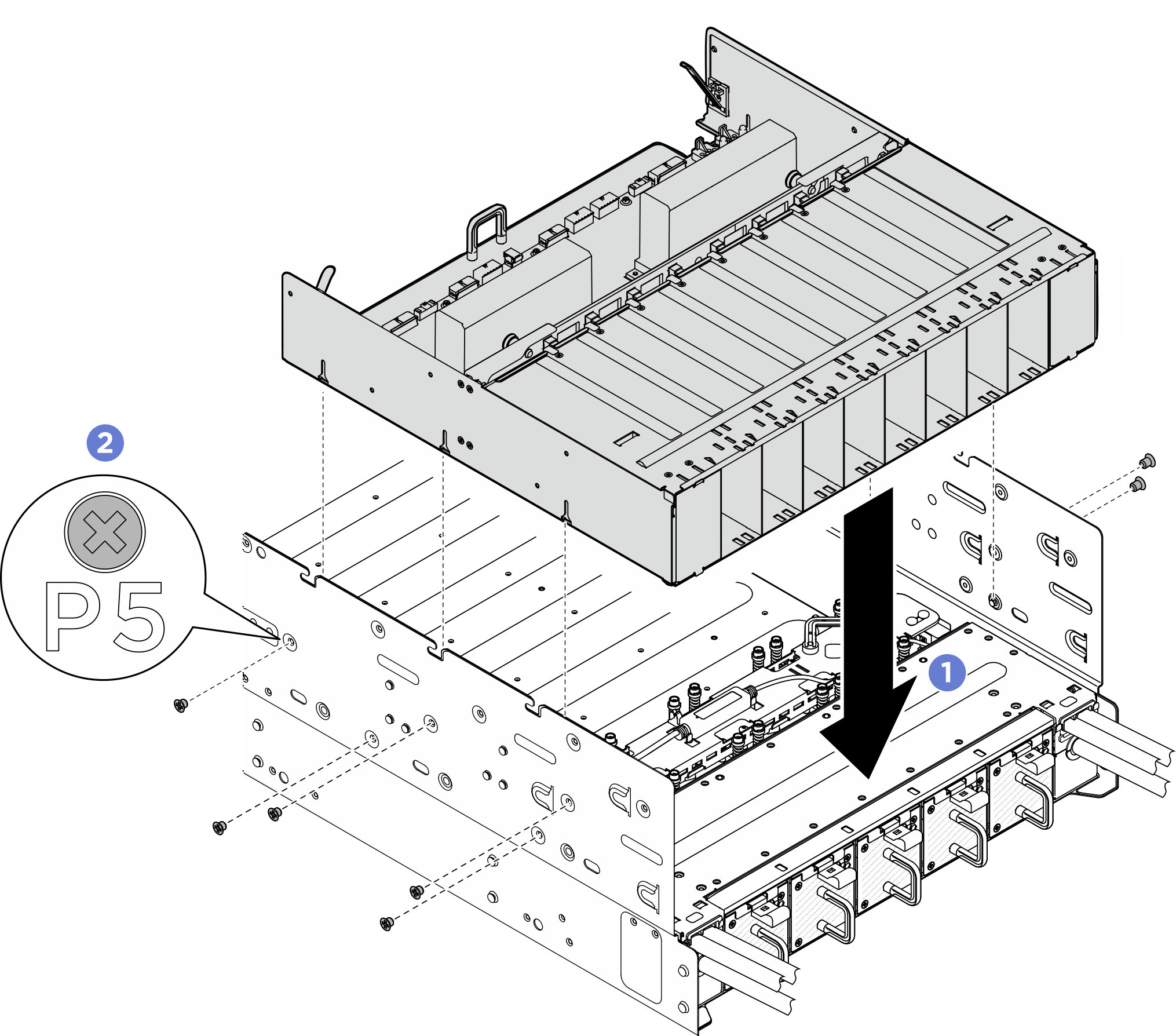
- If necessary, attach the labels to both ends of the power cable.
- Attach the white space portion of the label to one end of the cable.
- Wrap the label around the cable and attach it to the white space portion.
- Repeat to attach the other label to the opposite end of the cable.
Figure 2. Label application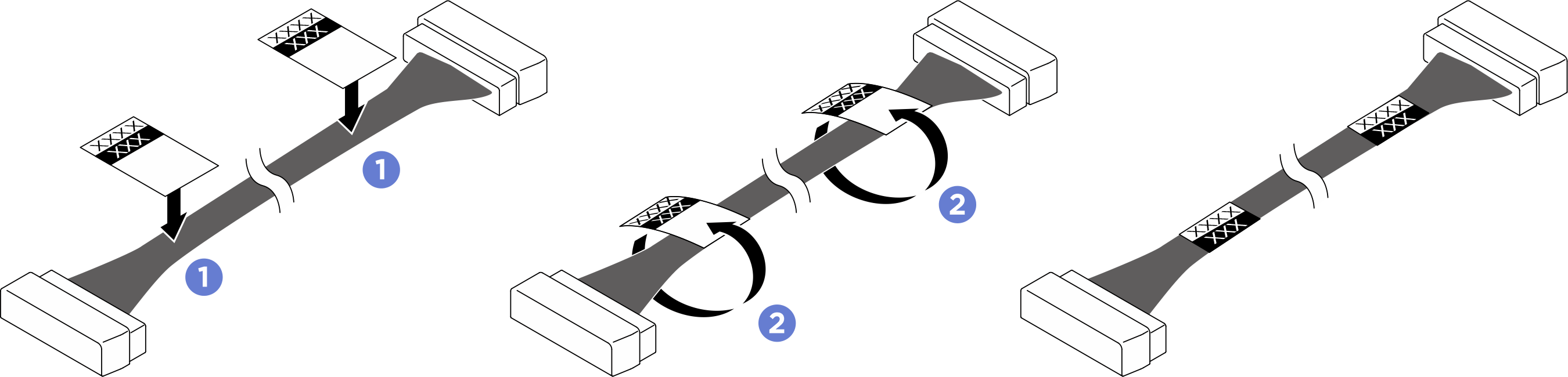 NoteSee the cable routing to identify the corresponding labels for the cable.
After you finish
- Reinstall the CPU complex. See Install the CPU complex.
- Reinstall the rear top cover. See Install the rear top cover.
- Reinstall the front top cover. See Install the front top cover.
- Reinstall all the power supply units. See Install a hot-swap power supply unit.
- Complete the parts replacement. See Complete the parts replacement.
Give documentation feedback