Install the PSU cage
Follow instructions in this section to install the PSU cage. The procedure must be executed by a trained technician.
About this task
Attention
- Read Installation Guidelines and Safety inspection checklist to ensure that you work safely.
- Touch the static-protective package that contains the component to any unpainted metal surface on the server; then, remove it from the package and place it on a static-protective surface.
Procedure
- Install the power distribution board.
- Fasten the ten screws (PH1, 10 x M3, 0.9 newton-meters, 8 inch-pounds) to secure the power distribution board.Figure 1. Power distribution board installation
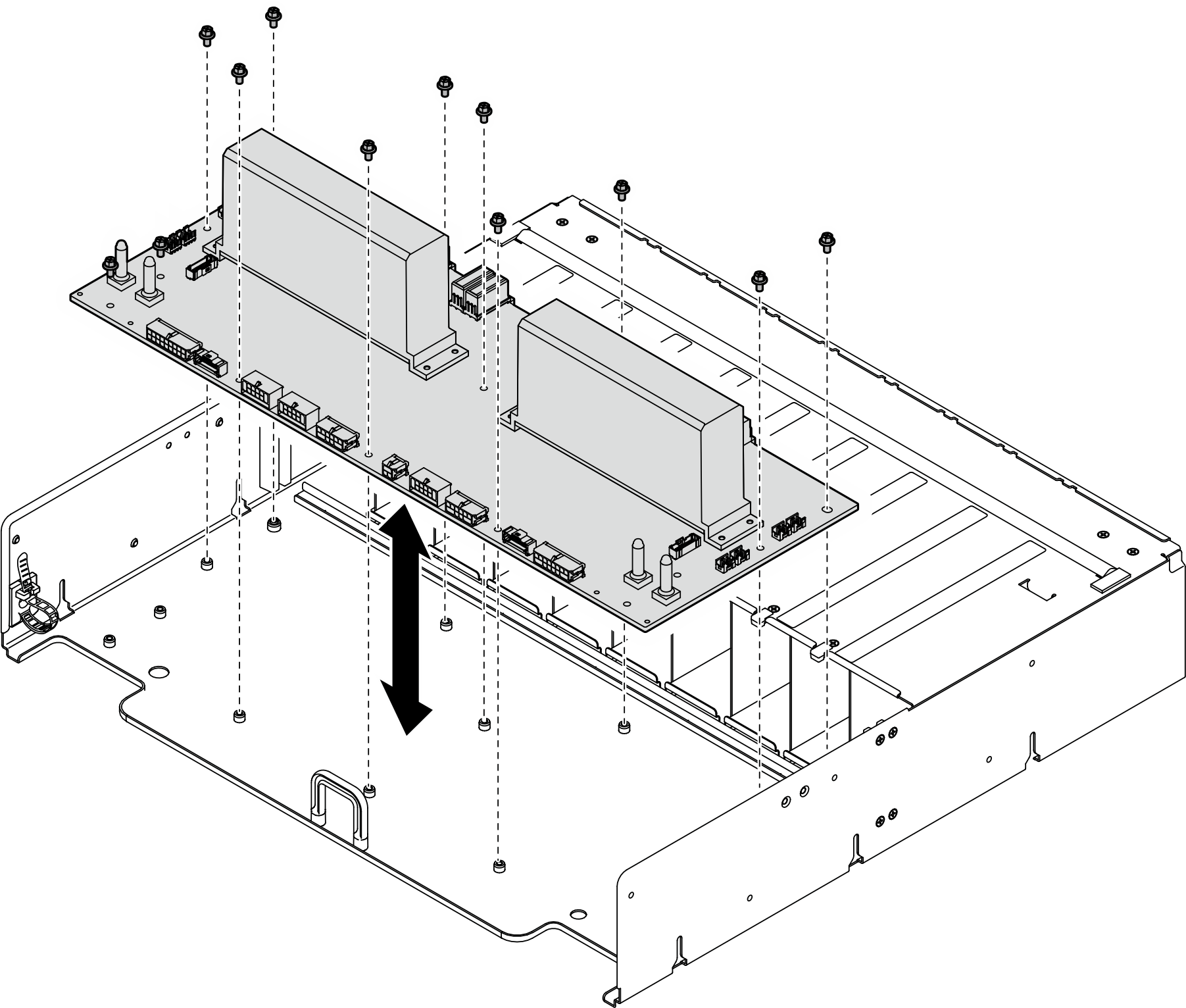
- Fasten the ten screws (PH1, 10 x M3, 0.9 newton-meters, 8 inch-pounds) to secure the power distribution board.
- Install the two cable retainers to the power distribution board.
- Repeat to install the other cable retainer.Figure 2. Cable retainer installation
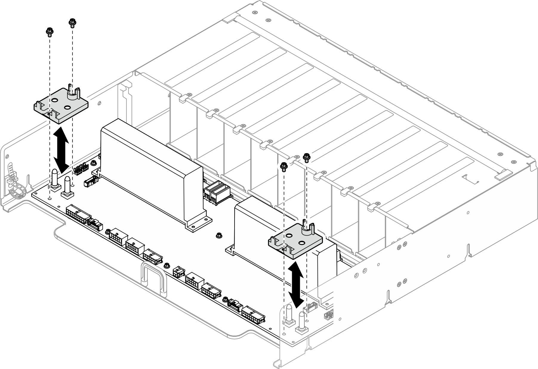
- Repeat to install the other cable retainer.
- Install the PSU interposer.
 Align the PSU interposer with its connectors on the power distribution board; then, press the PSU interposer into the connectors until it is fully seated.
 Pull out the two plungers.
 Rotate the two release latches down until they stop.Figure 3. PSU interposer installation
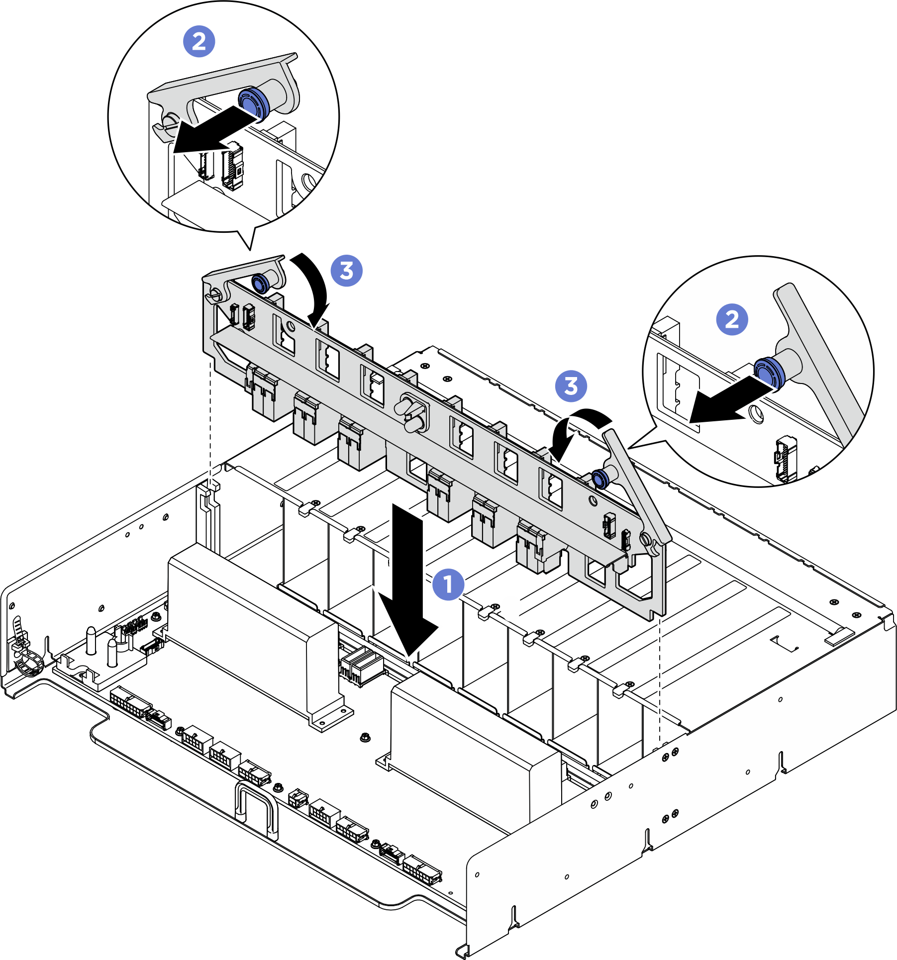
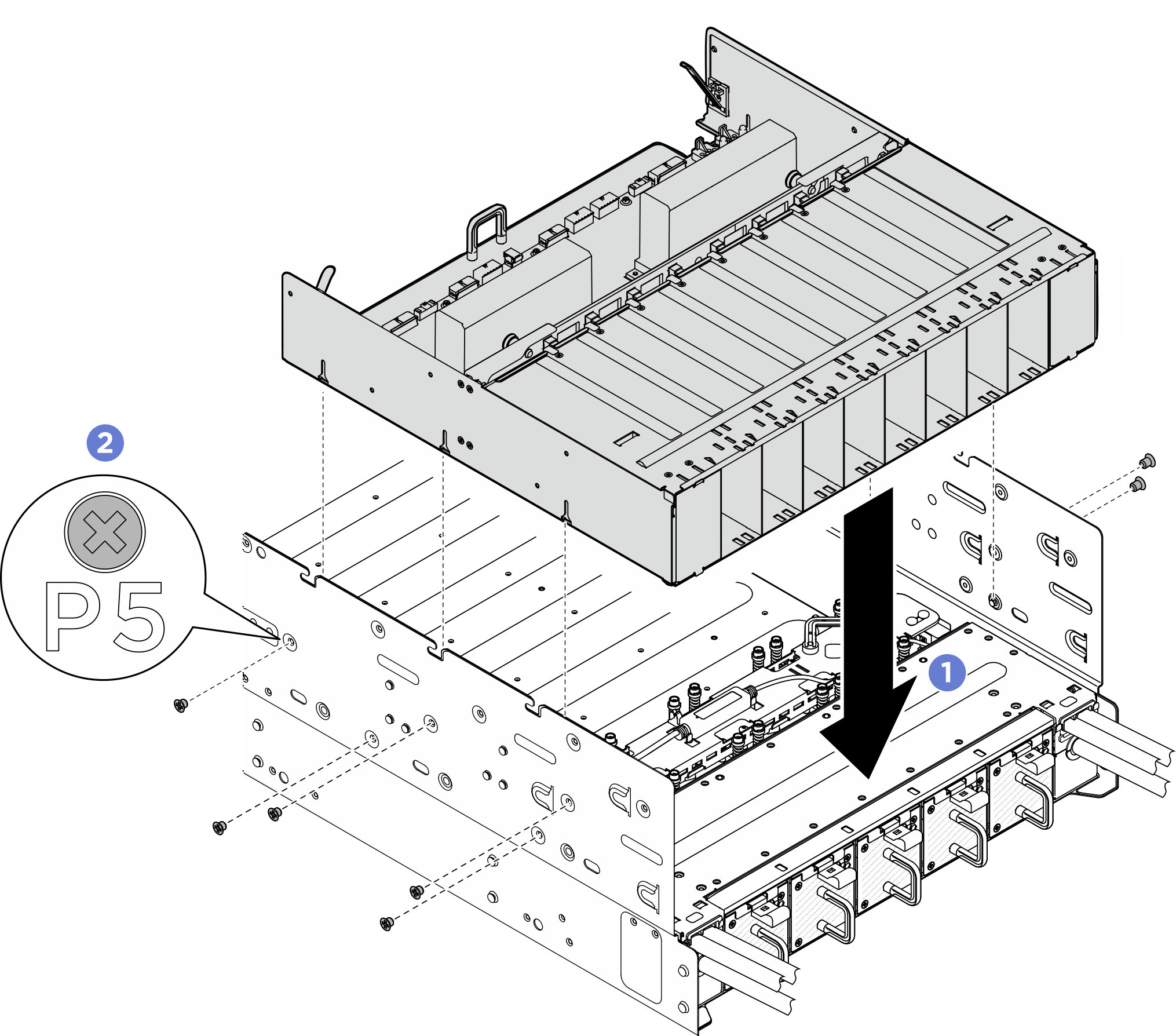
- Align the power complex with the six guide pins on the chassis; then, lower the power complex into the chassis until it is securely engaged.
- Locate the ten screw holes marked with P on both sides of the chassis; then, fasten the ten M3 screws (P1-P5) (PH2, 10 x M3, 0.5 newton-meters, 4.3 inch-pounds) to secure the power complex.Figure 4. Power complex installation
After you finish
- Reinstall the CPU complex. See Install the CPU complex.
- Reinstall the rear top cover. See Install the rear top cover.
- Reinstall the front top cover. See Install the front top cover.
- Reinstall all the power supply units. See Install a hot-swap power supply unit.
- Complete the parts replacement. See Complete the parts replacement.
Give documentation feedback