Install the system board
Follow instructions in this section to install the system board. The procedure must be executed by a trained technician.
About this task
Important
Removing and installing this component requires trained technicians. Do not attempt to remove or install it without proper training.
Attention
- Read Installation Guidelines and Safety inspection checklist to ensure that you work safely.
- Touch the static-protective package that contains the component to any unpainted metal surface on the server; then, remove it from the package and place it on a static-protective surface.
Firmware and driver download: You might need to update the firmware or driver after replacing a component.
Go to Drivers and Software download website for ThinkSystem SR780a V3 to see the latest firmware and driver updates for your server.
Go to Update the firmware for more information on firmware updating tools.
Procedure
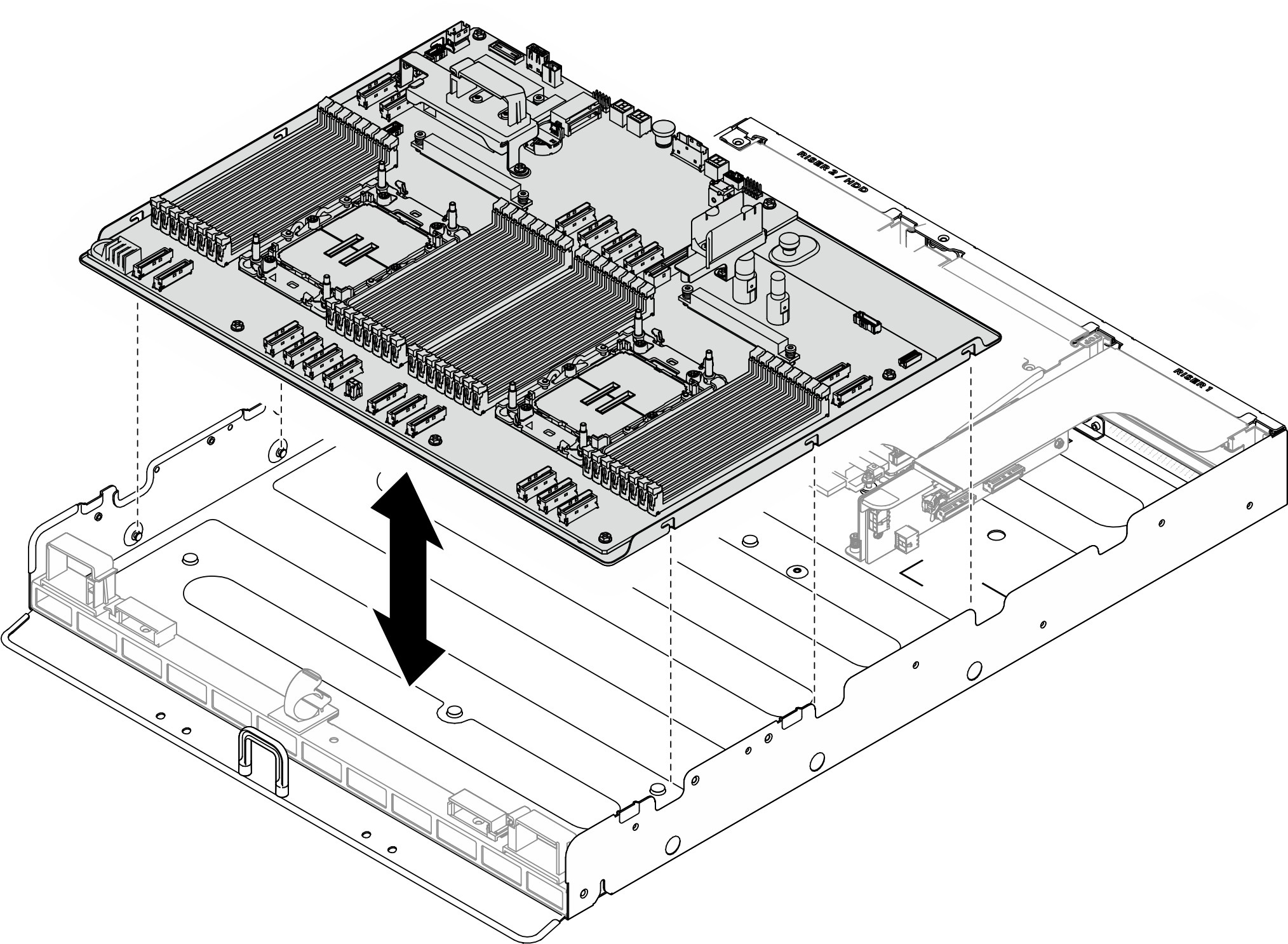
- Align the system board with the guide pins and lower the system board into the chassis.Figure 1. System board installation
- Secure the system board to the chassis.
 Slide the system board towards the rear of the server until it is engaged with the pins as illustrated.
 Tighten the (1) thumbscrew to secure the system board in place.
Figure 2. Securing the system board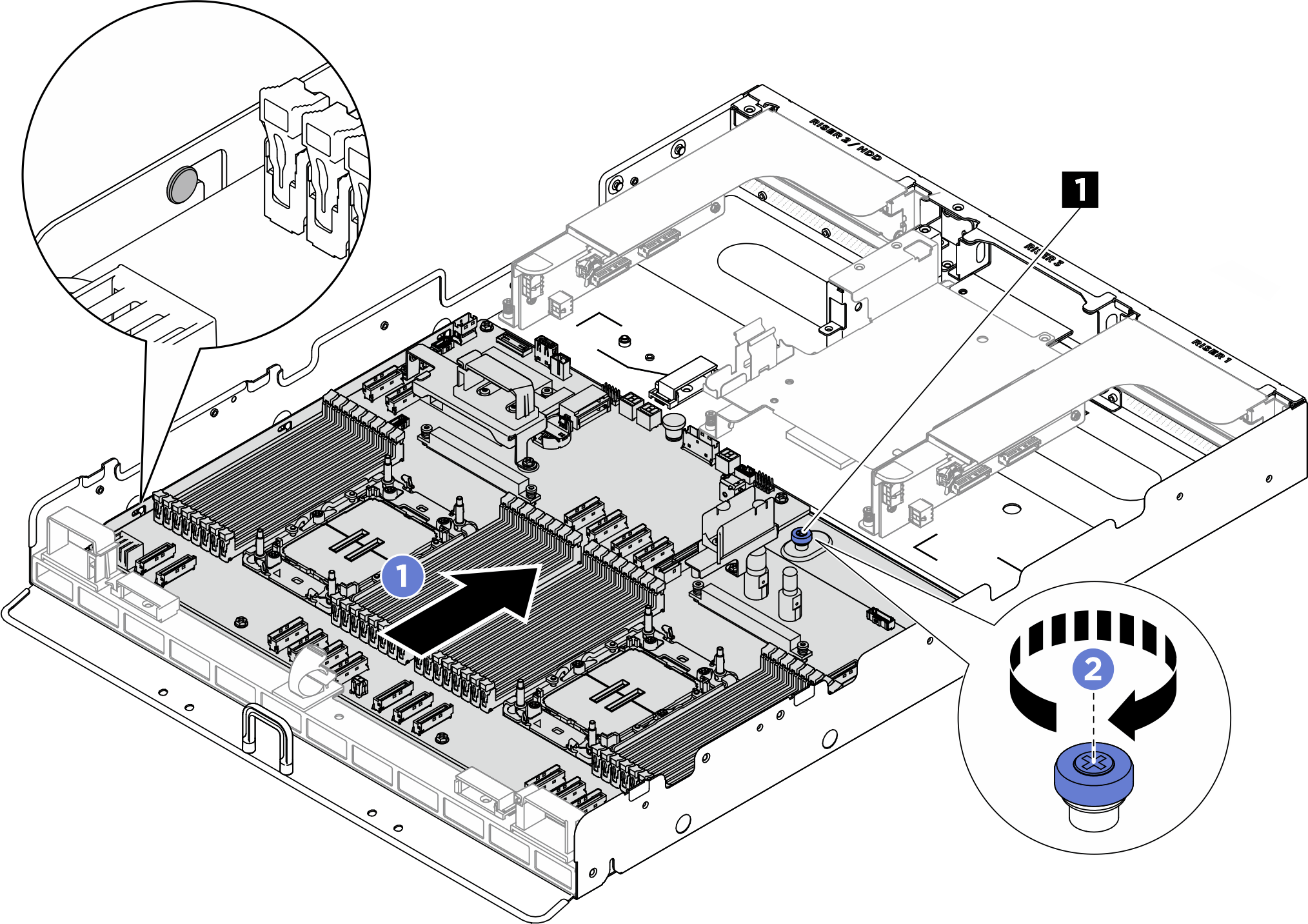
1 Thumbscrew - Install the cable guides.
- Fasten the two M3 screws (PH2, 2 x M3, 0.5 newton-meters, 4.3 inch-pounds) to secure the cable guide to the chassis.Figure 3. Cable guide installation
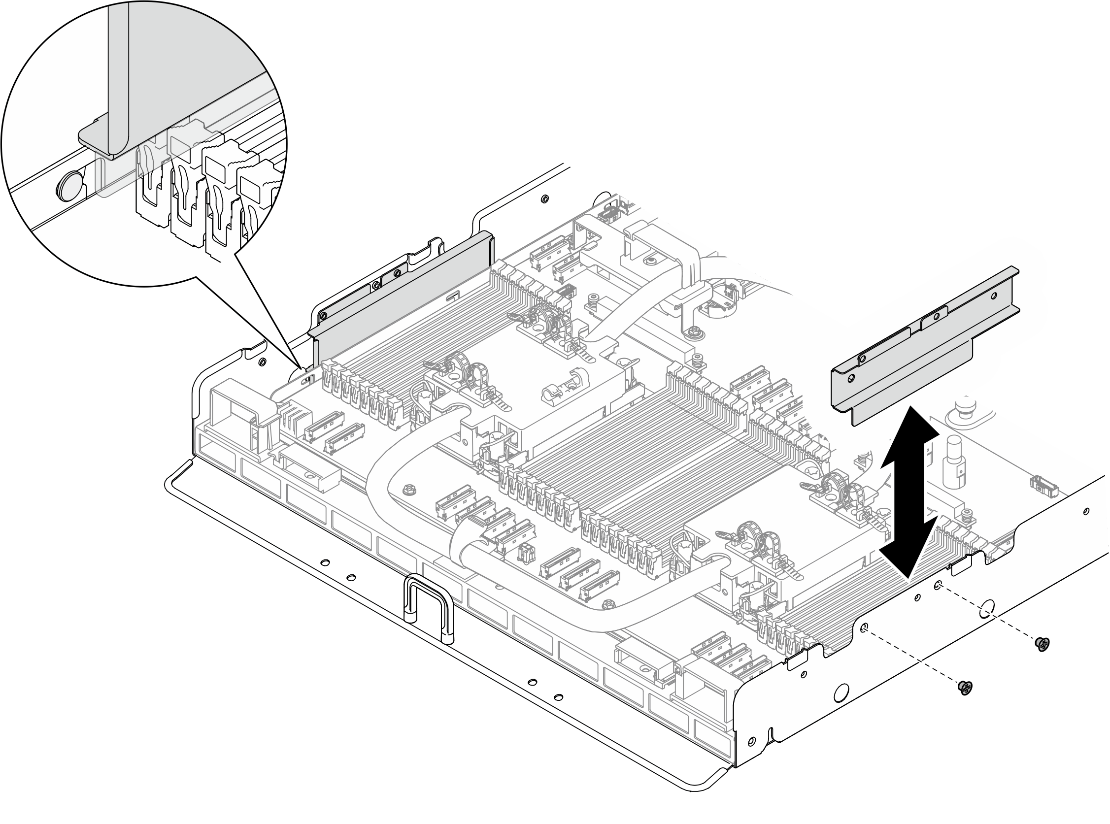
- Fasten the two M3 screws (PH2, 2 x M3, 0.5 newton-meters, 4.3 inch-pounds) to secure the cable guide to the chassis.
After you finish
- Reinstall the following components.
- Reinstall each memory module to the same slot on the new system board assembly as on the defective system board assembly until all the memory modules are installed. See Install a memory module.
- If applicable, reinstall the system I/O board. See Install the system I/O board.
- Reinstall the Lenovo Processor Neptune® Core Module. See Install the Lenovo Processor Neptune® Core Module.
- If applicable, reinstall the leakage sensor module bracket. See Install the leakage sensor module bracket.
- If applicable, reinstall the PCIe riser assembly(ies). See Install a PCIe riser assembly.
- If applicable, reinstall the rear drive cage. See Install the rear drive cage.
- Reconnect all the required cables to the same connectors on the system board as the defective system board.
- Ensure that all components have been reassembled correctly and that no tools or loose screws are left inside the server.
- Reinstall the processor air baffle. See Install the processor air baffle.
- Power on the server and any peripheral devices. See Power on the server.
- Update the vital product data (VPD). See Update the Vital Product Data (VPD). Machine type number and serial number can be found on the ID label, see Identify the server and access the Lenovo XClarity Controller.
- Optionally, enable UEFI Secure Boot. See Enable UEFI Secure Boot.
Give documentation feedback