PCIe riser 1 cable routing
Follow the instructions in this section to learn how to do cable routing for the PCIe riser 1.
When routing the cables, make sure that all cables are routed appropriately through the corresponding cable guides and cable clips.
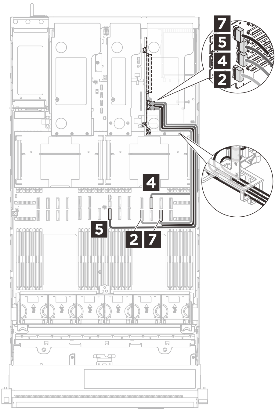
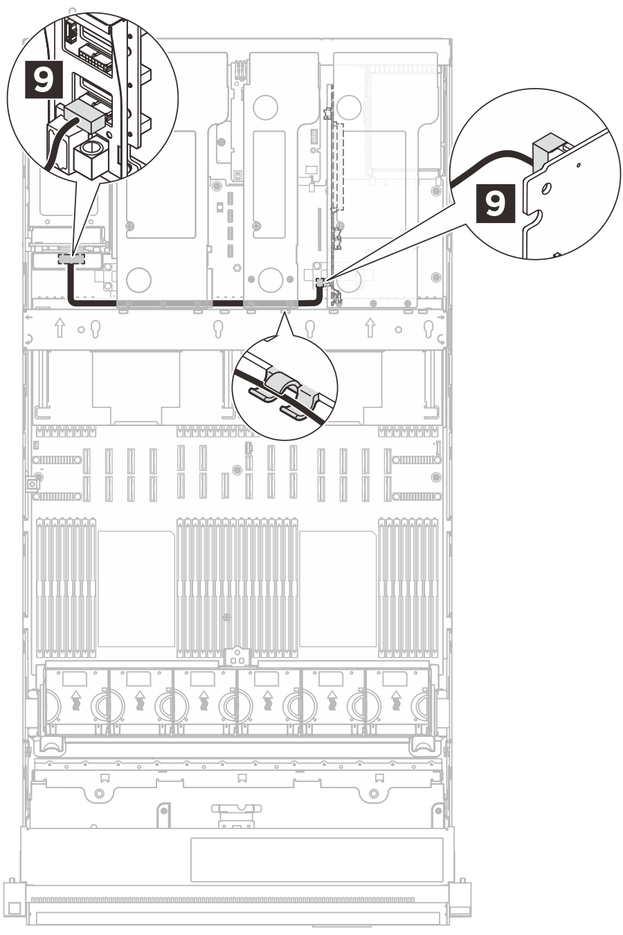
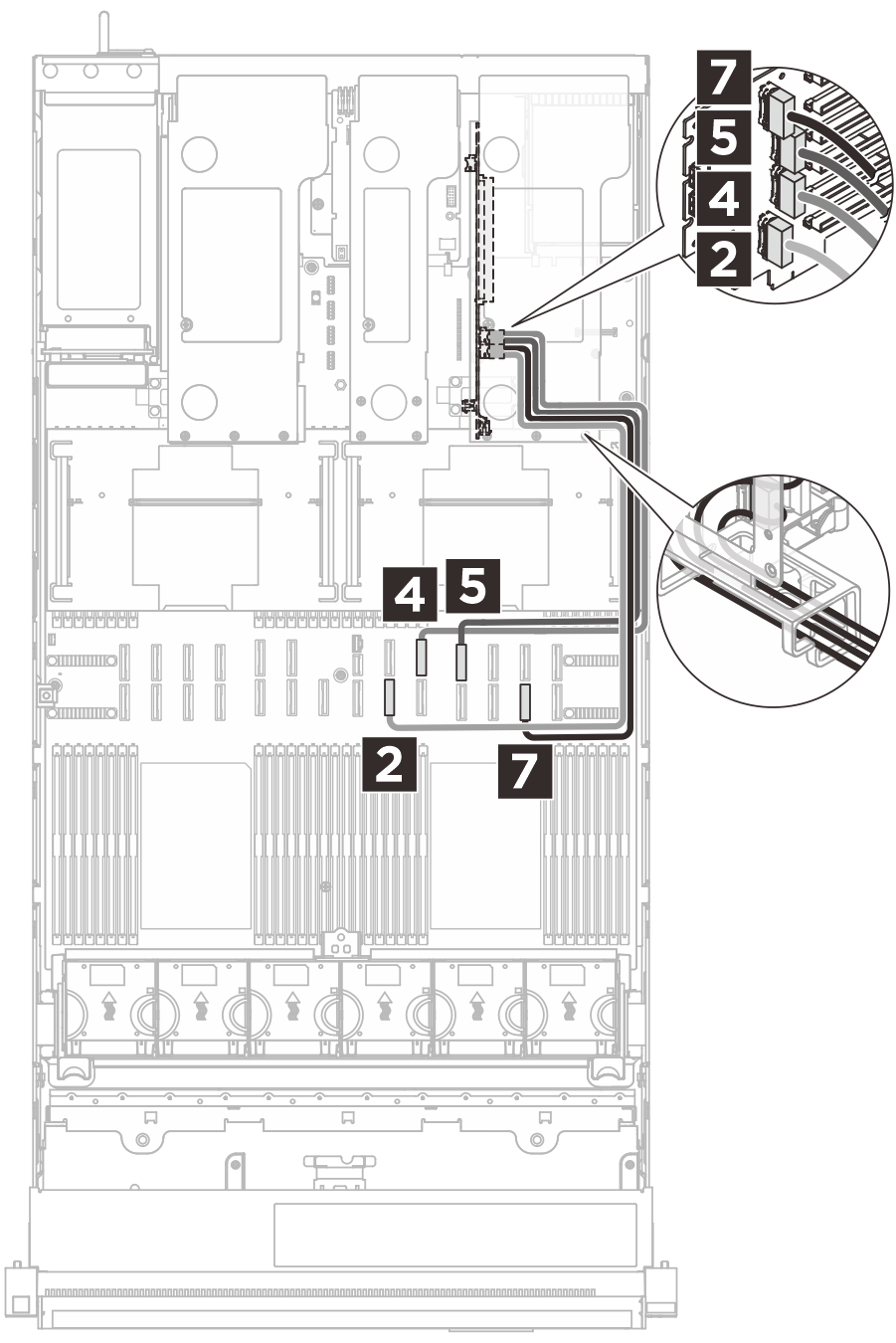
Six-slot PCIe Gen5 riser 1 cable routing
The following illustration shows cable routing for the six-slot PCIe Gen5 riser 1.
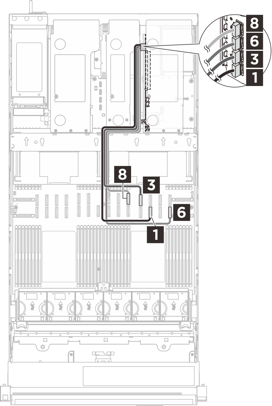 |  |  |
| Cable | From (riser card) | To (system board assembly) |
|---|---|---|
| MCIO x8 to Swift x8 (600 mm, flat 140 mm) | 1 R1 | 1 P12 |
| MCIO x8 to Swift x8 (500 mm) | 2 R2 | 2 P11 |
| MCIO x8 to Swift x8 (600 mm, flat 140 mm) | 3 R3 | 3 P22* |
| MCIO x8 to Swift x8 (500 mm) | 4 R4 | 4 P23* |
| MCIO x8 to Swift x8 (620 mm) | 5 R5 | 5 P8 |
| MCIO x8 to Swift x8 (600 mm, flat 140 mm) | 6 R6 | 6 P14 |
| MCIO x8 to Swift x8 (500 mm) | 7 R7 | 7 P13 |
| MCIO x8 to Swift x8 (540 mm, flat 140 mm) | 8 R8 | 8 P21 |
| Micro-Hi 2x8p to Micro-Hi 2x8p (400 mm) | 9 Power connector | 9 PDB: riser 1 power connector |
*Connectors P22 and P23 on the system board assembly are designated for E3.S backplane connection in server models with E3.S bays. PCIe slot 6 on the riser is unavailable for server models with E3.S bays.
Six-slot PCIe Gen5 riser 1 cable routing (with liquid-cooling module)
The following illustration shows cable routing for the six-slot PCIe Gen5 riser 1 in the server with the Processor Neptune® Core Module (liquid-cooling module) installed.
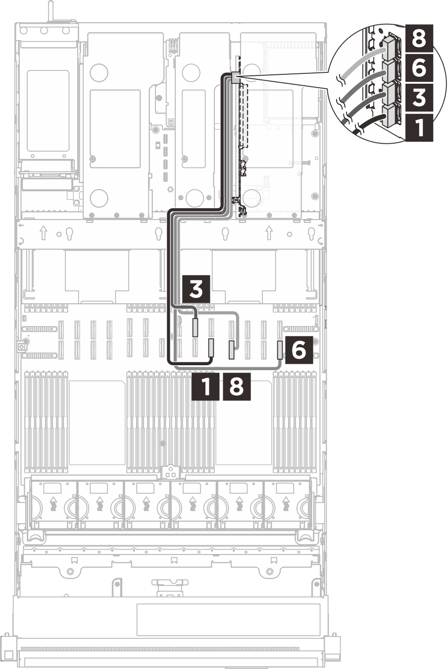 |  | |
| Cable | From (riser card) | To (system board assembly) |
|---|---|---|
| MCIO x8 to Swift x8 (500 mm, flat 140 mm) | 1 R1 | 1 P10 |
| MCIO x8 to Swift x8 (500 mm) | 2 R2 | 2 P9 |
| MCIO x8 to Swift x8 (500 mm, flat 140 mm) | 3 R3 | 3 P20 |
| MCIO x8 to Swift x8 (500 mm) | 4 R4 | 4 P21 |
| MCIO x8 to Swift x8 (500 mm) | 5 R5 | 5 P22* |
| MCIO x8 to Swift x8 (600 mm, flat 140 mm) | 6 R6 | 6 P14 |
| MCIO x8 to Swift x8 (500 mm) | 7 R7 | 7 P13 |
| MCIO x8 to Swift x8 (540 mm, flat 140 mm) | 8 R8 | 8 P11 |
| Micro-Hi 2x8p to Micro-Hi 2x8p (400 mm) | 9 Power connector | 9 PDB: riser 1 power connector |
*Connector P22 on the system board assembly is designated for E3.S backplane connection in server models with E3.S bays. PCIe slot 5 on the riser is unavailable for server models with E3.S bays.
Two-slot PCIe Gen4 riser 1 cable routing
The following illustration shows cable routing for the two-slot PCIe Gen4 riser 1.
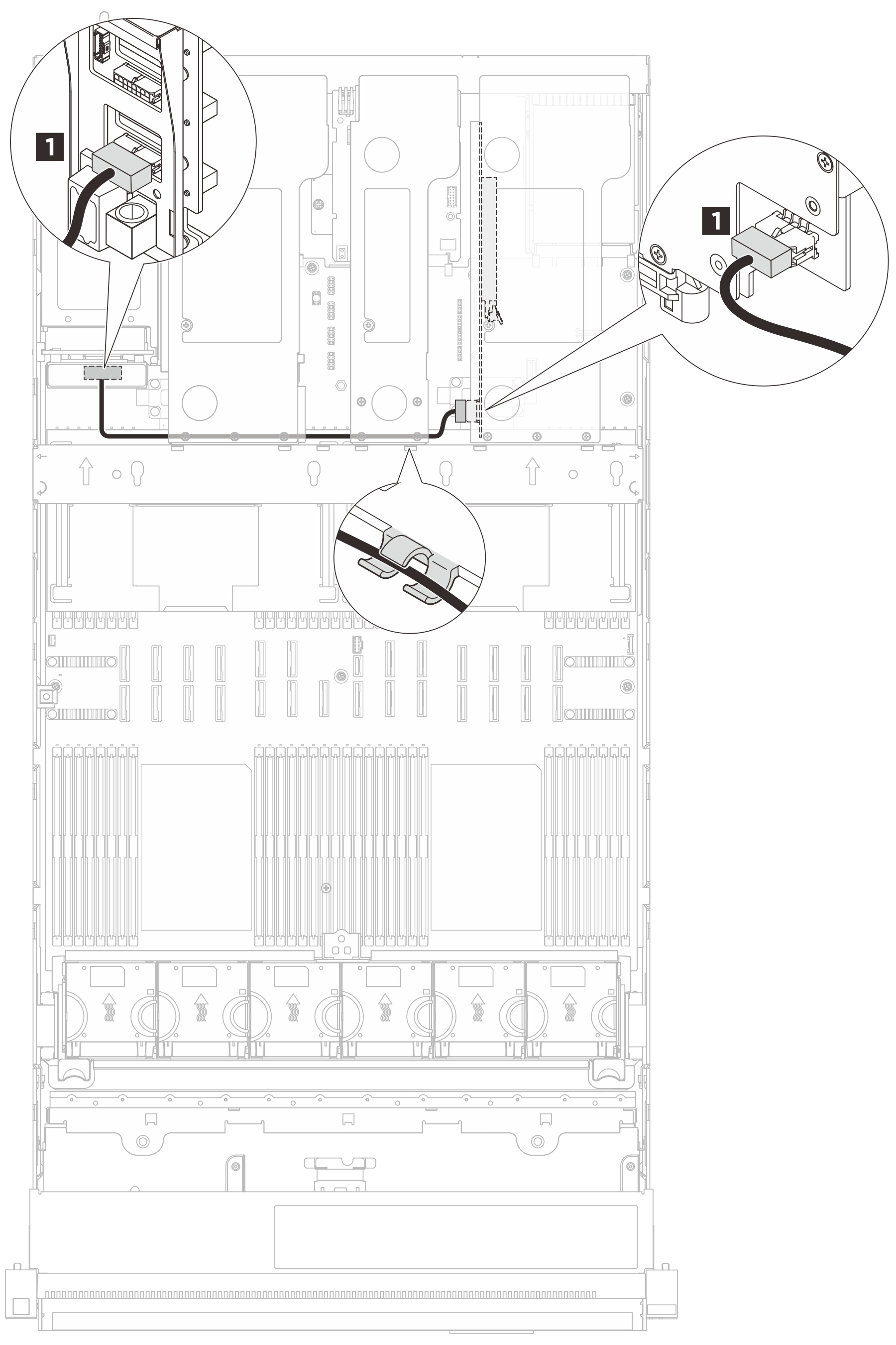
| Cable | From | To |
|---|---|---|
| Micro-Hi 2x8p to Micro-Hi 2x4p (330 mm) | 1 Riser: power connector | 1 PDB: riser 1 power connector |