E3.S backplane cable routing
Use the section to understand the cable routing for the E3.S backplanes.
When routing the cables, make sure that all cables are routed appropriately through the corresponding cable guides and cable clips.
Backplane numbering
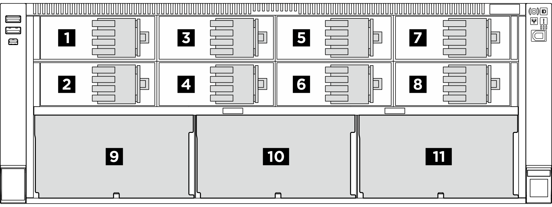
| Drive backplane | E3.S 1T bay | E3.S 2T bay | 2.5-inch SAS/SATA bay |
|---|---|---|---|
| 1 Backplane 1 | 0 to 3 | 1, 3 | |
| 2 Backplane 2 | 4 to 7 | 5, 7 | |
| 3 Backplane 3 | 8 to 11 | 9, 11 | |
| 4 Backplane 4 | 12 to 15 | 13, 15 | |
| 5 Backplane 5 | 16 to 19 | 17, 19 | |
| 6 Backplane 6 | 20 to 23 | 21, 23 | |
| 7 Backplane 7 | 24 to 27 | 25, 27 | |
| 8 Backplane 8 | 28 to 31 | 29, 31 | |
| 9 Backplane 9 | 32 to 39 | ||
| 10 Backplane 10 | 40 to 47 | ||
| 11 Backplane 11 | 48 to 55 |
E3.S 1T bays support E3.S 1T drives.
E3.S 2T bays support CXL memory modules (CMMs).
| Backplane type | Backplane quantity | Backplane placement priority |
|---|---|---|
| E3.S backplane for E3.S 1T bays | 2 | 1, 2 |
| 4 | 1, 2, 3, 4 | |
| 6 | 1, 2, 3, 4, 5, 6 | |
| 8 | 1, 2, 3, 4, 5, 6, 7, 8 | |
| E3.S backplane for E3.S 2T bays | 8 | 1, 2, 3, 4, 5, 6, 7, 8 |
| 2.5-inch SAS/SATA 8-bay drive backplane | 1 | 9 |
| 2 | 9, 10 | |
| 3 | 9, 10, 11 |
Power cable routing
| E3.S backplane power cable routing | SAS/SATA backplane power cable routing |
|---|---|
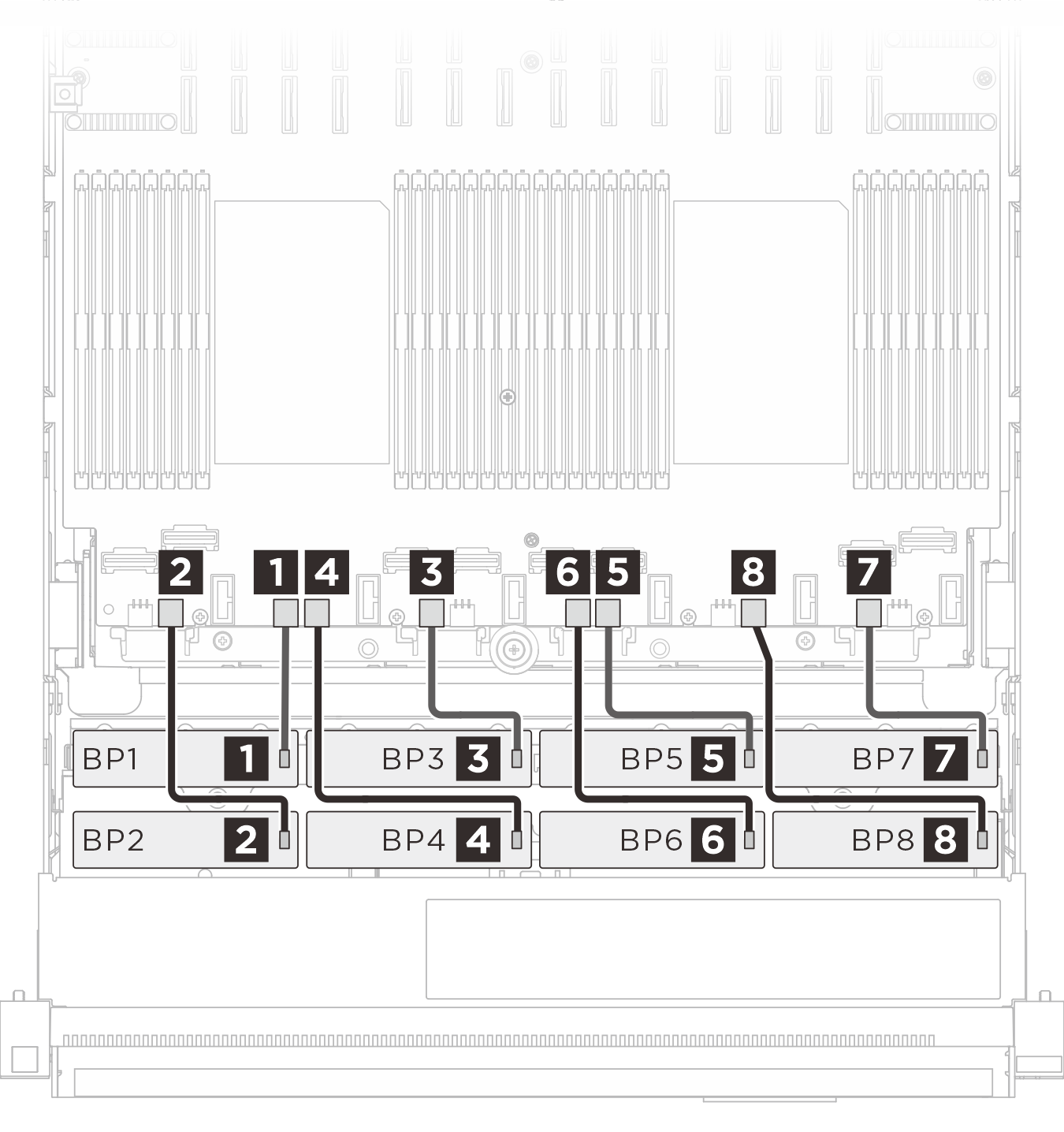 | 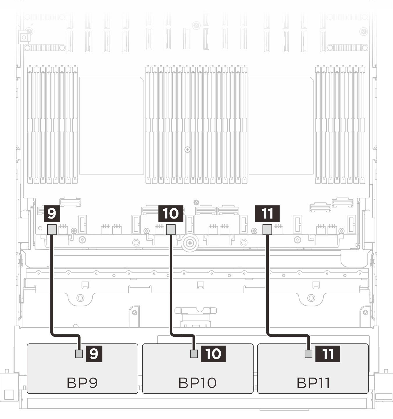 |
| Cable | From (backplane) | To (system board assembly) |
|---|---|---|
| MPIC 6p+6s to MPIC 6p+6s (230 mm) | 1 BP 1: PWR | 1 BP 3 PWR |
| MPIC 6p+6s to MPIC 6p+6s (230 mm) | 2 BP 2: PWR | 2 BP 2 PWR |
| MPIC 6p+6s to MPIC 6p+6s (230 mm) | 3 BP 3: PWR | 3 BP 5 PWR |
| MPIC 6p+6s to MPIC 6p+6s (230 mm) | 4 BP 4: PWR | 4 BP 4 PWR |
| MPIC 6p+6s to MPIC 6p+6s (230 mm) | 5 BP 5: PWR | 5 BP 8 PWR |
| MPIC 6p+6s to MPIC 6p+6s (230 mm) | 6 BP 6: PWR | 6 BP 7 PWR |
| MPIC 6p+6s to MPIC 6p+6s (230 mm) | 7 BP 7: PWR | 7 BP 11: PWR |
| MPIC 6p+6s to MPIC 6p+6s (230 mm) | 8 BP 8: PWR | 8 BP 10: PWR |
| MPIC 6p+6s to MPIC 6p+6s (150 mm) | 9 BP 9: PWR | 9 BP 1: PWR |
| MPIC 6p+6s to MPIC 6p+6s (150 mm) | 10 BP 10: PWR | 10 BP 6: PWR |
| MPIC 6p+6s to MPIC 6p+6s (150 mm) | 11 BP 11: PWR | 11 BP 9: PWR |
E3.S 1T signal cable routing
| BP1/BP2 signal cable routing | BP3/BP4 signal cable routing |
|---|---|
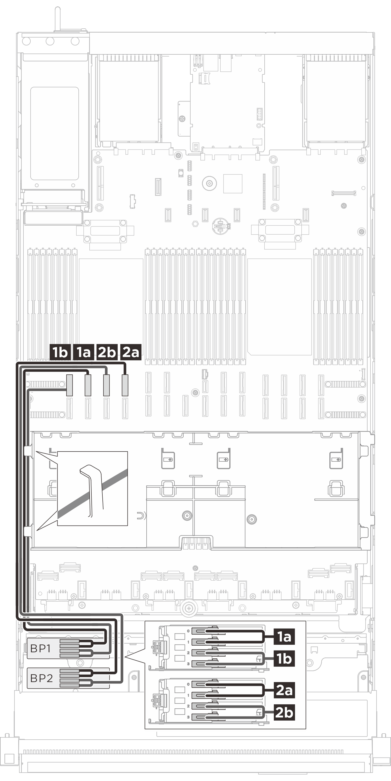 |  |
| Cable | From (backplane) | To (system board assembly) |
|---|---|---|
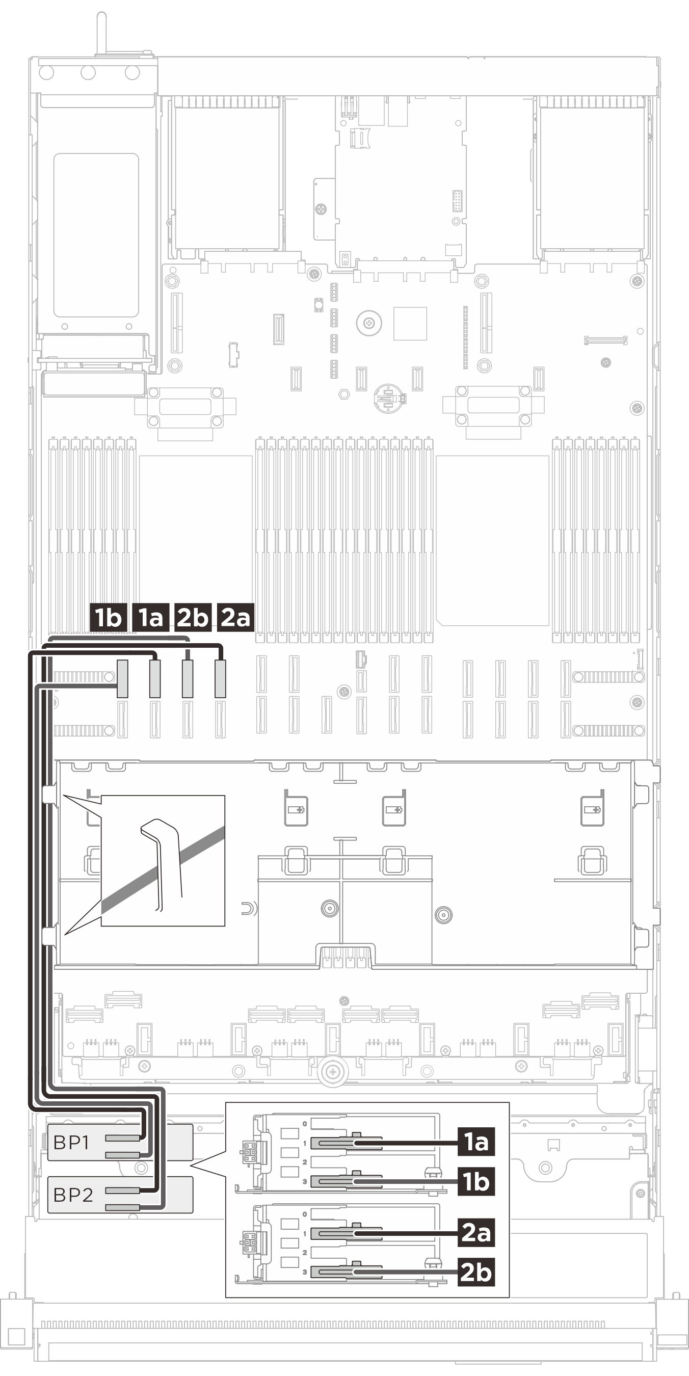
| MCIO x8 to Gen-Z 1C*2 (560 mm) | 1a BP 1: Bay 0, Bay 1 | 1a NVMe 10 |
| MCIO x8 to Gen-Z 1C*2 (560 mm) | 1b BP 1: Bay 2, Bay 3 | 1b NVMe 9 |
| MCIO x8 to Gen-Z 1C*2 (560 mm) | 2a BP 2: Bay 0, Bay 1 | 2a NVMe 14 |
| MCIO x8 to Gen-Z 1C*2 (560 mm) | 2b BP 2: Bay 2, Bay 3 | 2b NVMe 13 |
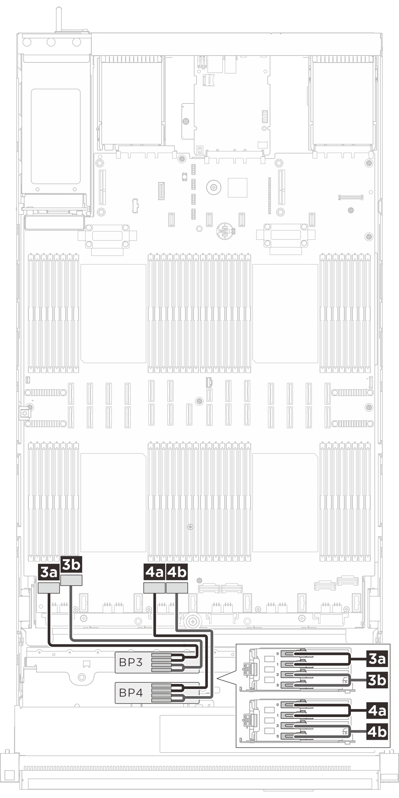
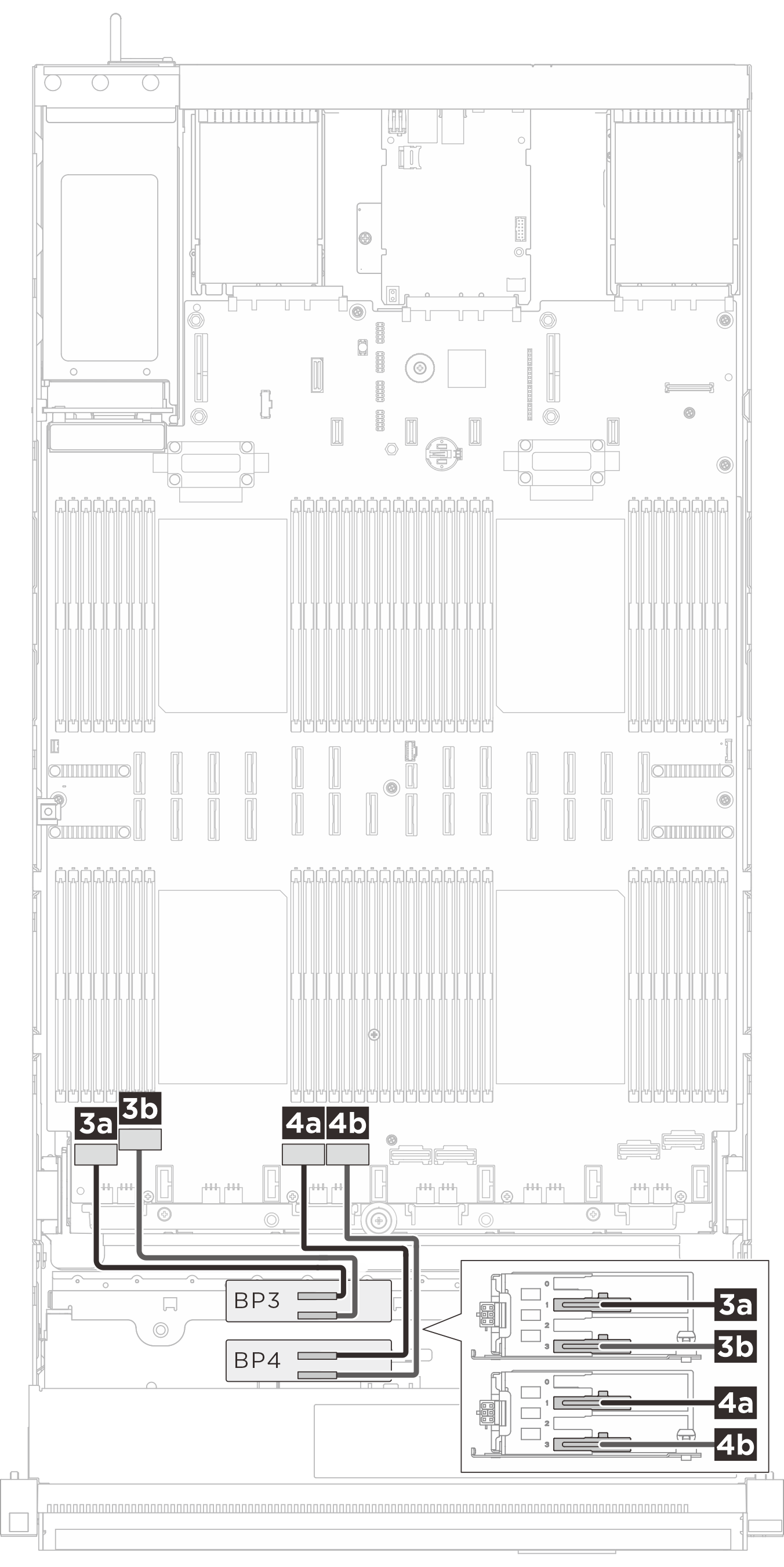
| Swift x8 to Gen-Z 1C*2 (330 mm) | 3a BP 3: Bay 0, Bay 1 | 3a NVMe 1 |
| Swift x8 to Gen-Z 1C*2 (330 mm) | 3b BP 3: Bay 2, Bay 3 | 3b NVMe 2 |
| Swift x8 to Gen-Z 1C*2 (330 mm) | 4a BP 4: Bay 0, Bay 1 | 4a NVMe 3 |
| Swift x8 to Gen-Z 1C*2 (330 mm) | 4b BP 4: Bay 2, Bay 3 | 4b NVMe 4 |
| BP5/BP6 signal cable routing | BP7/BP8 signal cable routing |
|---|---|
 |  |
| Cable | From (backplane) | To (system board assembly) |
|---|---|---|
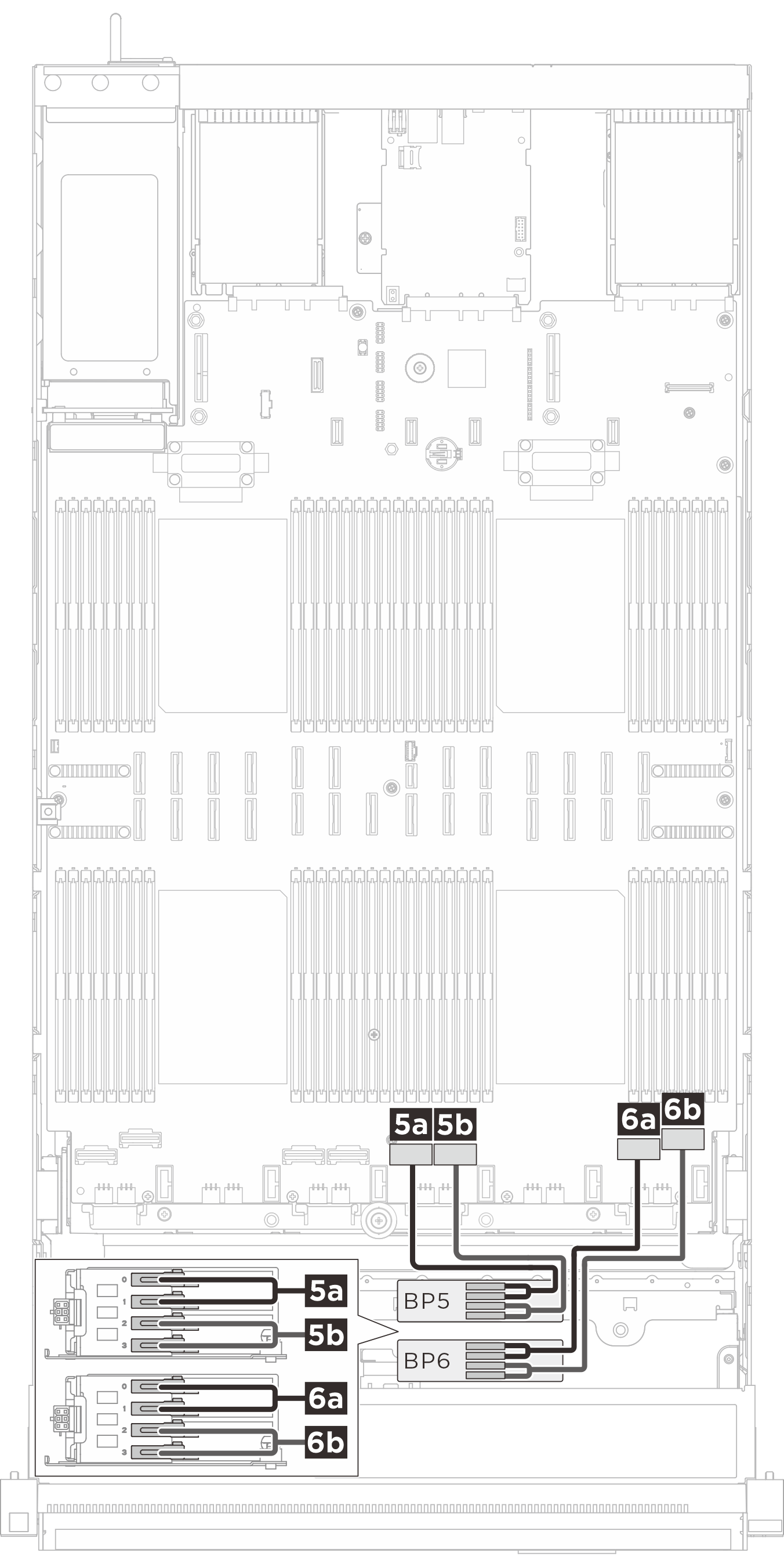
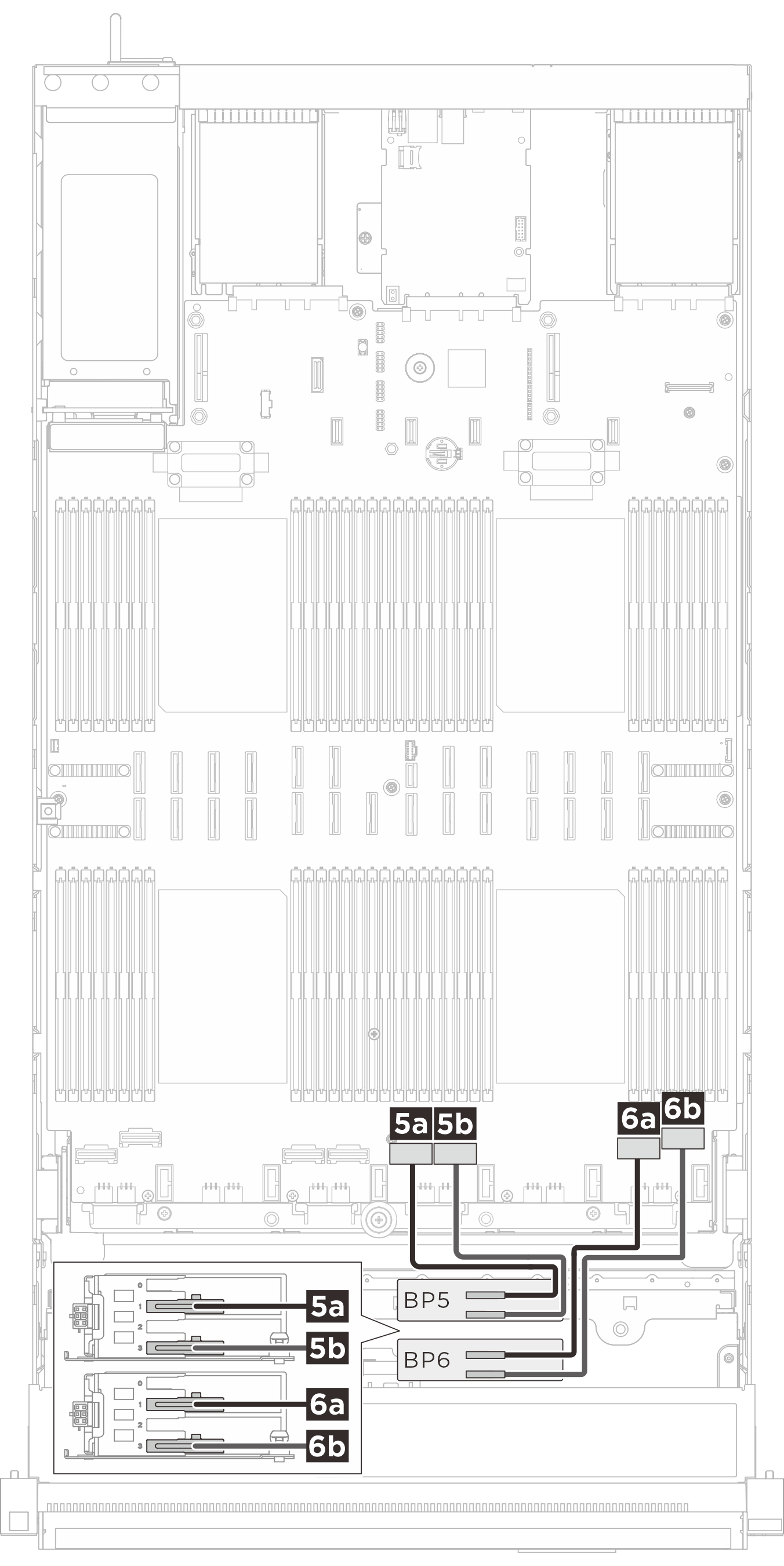
| Swift x8 to Gen-Z 1C*2 (330 mm) | 5a BP 5: Bay 0, Bay 1 | 5a NVMe 5 |
| Swift x8 to Gen-Z 1C*2 (330 mm) | 5b BP 5: Bay 2, Bay 3 | 5b NVMe 6 |
| Swift x8 to Gen-Z 1C*2 (330 mm) | 6a BP 6: Bay 0, Bay 1 | 6a NVMe 7 |
| Swift x8 to Gen-Z 1C*2 (330 mm) | 6b BP 6: Bay 2, Bay 3 | 6b NVMe 8 |
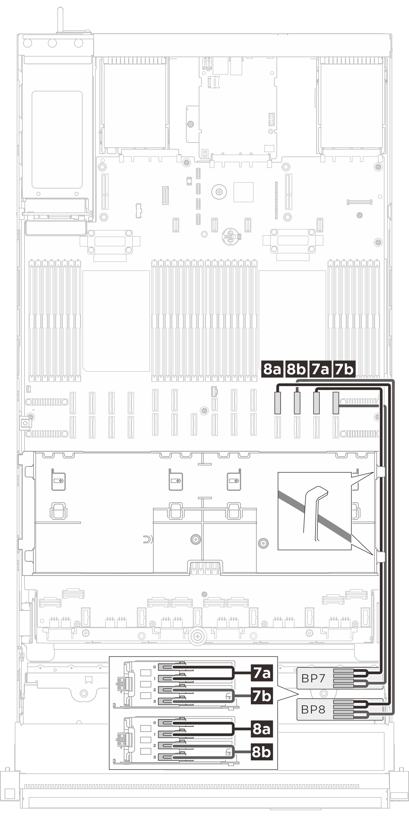
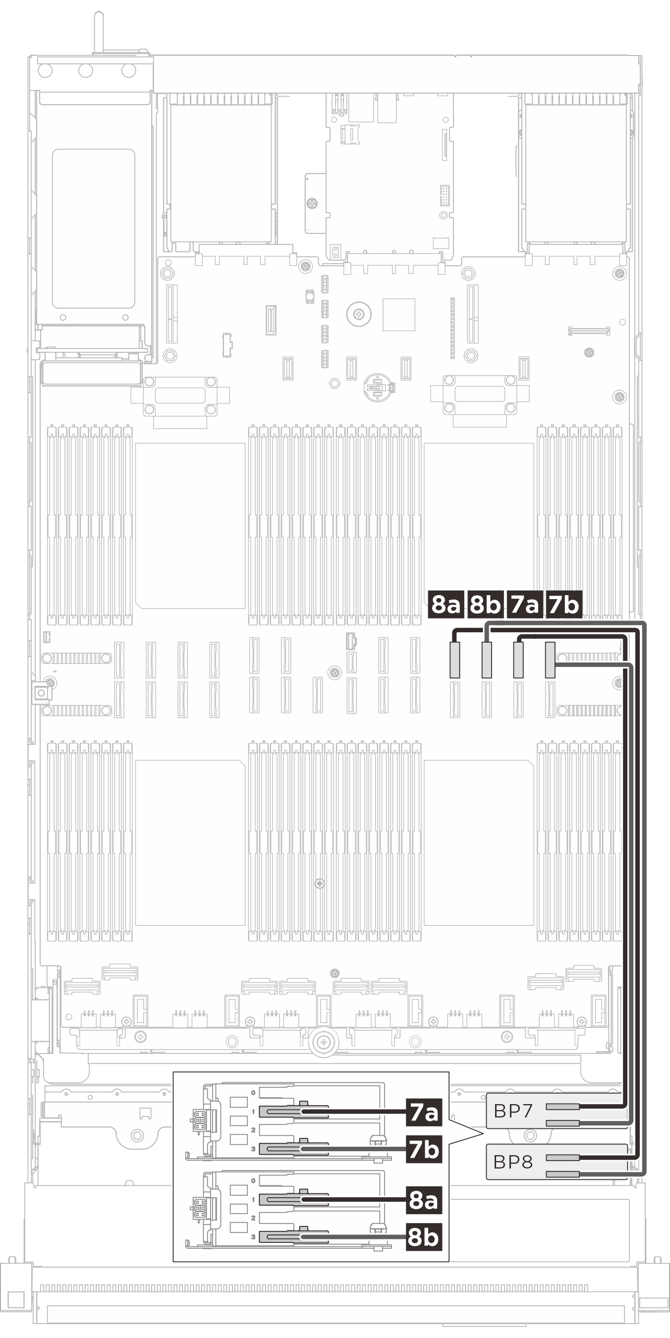
| MCIO x8 to Gen-Z 1C*2 (560 mm) | 7a BP 7: Bay 0, Bay 1 | 7a NVMe 11 |
| MCIO x8 to Gen-Z 1C*2 (560 mm) | 7b BP 7: Bay 2, Bay 3 | 7b NVMe 12 |
| MCIO x8 to Gen-Z 1C*2 (560 mm) | 8a BP 8: Bay 0, Bay 1 | 8a NVMe 15 |
| MCIO x8 to Gen-Z 1C*2 (560 mm) | 8b BP 8: Bay 2, Bay 3 | 8b NVMe 16 |
E3.S 2T signal cable routing
| BP1/BP2 signal cable routing | BP3/BP4 signal cable routing |
|---|---|
 |  |
| Cable | From (backplane) | To (system board assembly) |
|---|---|---|
| MCIO x8 to Gen-Z 2C (560 mm) | 1a BP 1: Bay 1 | 1a NVMe 10 |
| MCIO x8 to Gen-Z 2C (560 mm) | 1b BP 1: Bay 3 | 1b NVMe 9 |
| MCIO x8 to Gen-Z 2C (560 mm) | 2a BP 2: Bay 1 | 2a NVMe 14 |
| MCIO x8 to Gen-Z 2C (560 mm) | 2b BP 2: Bay 3 | 2b NVMe 13 |
| Swift x8 to Gen-Z 2C (330 mm) | 3a BP 3: Bay 1 | 3a NVMe 1 |
| Swift x8 to Gen-Z 2C (330 mm) | 3b BP 3: Bay 3 | 3b NVMe 2 |
| Swift x8 to Gen-Z 2C (330 mm) | 4a BP 4: Bay 1 | 4a NVMe 3 |
| Swift x8 to Gen-Z 2C (330 mm) | 4b BP 4: Bay 3 | 4b NVMe 4 |
| BP5/BP6 signal cable routing | BP7/BP8 signal cable routing |
|---|---|
 |  |
| Cable | From (Backplane) | To (System board assembly) |
|---|---|---|
| Swift x8 to Gen-Z 2C (330 mm) | 5a BP 5: Bay 1 | 5a NVMe 5 |
| Swift x8 to Gen-Z 2C (330 mm) | 5b BP 5: Bay 3 | 5b NVMe 6 |
| Swift x8 to Gen-Z 2C (330 mm) | 6a BP 6: Bay 1 | 6a NVMe 7 |
| Swift x8 to Gen-Z 2C (330 mm) | 6b BP 6: Bay 3 | 6b NVMe 8 |
| MCIO x8 to Gen-Z 2C (560 mm) | 7a BP 7: Bay 1 | 7a NVMe 11 |
| MCIO x8 to Gen-Z 2C (560 mm) | 7b BP 7: Bay 3 | 7b NVMe 12 |
| MCIO x8 to Gen-Z 2C (560 mm) | 8a BP 8: Bay 1 | 8a NVMe 15 |
| MCIO x8 to Gen-Z 2C (560 mm) | 8b BP 8: Bay 3 | 8b NVMe 16 |
SAS/SATA backplane signal cable routing
Gen 4 RAID/HBA adapters: 545-8i/940-8i/940-16i/440-16i
1 x backplane: 1 x RAID/HBA 8i
2 x backplanes: 1 x RAID/HBA 16i
3 x backplanes: 1 x RAID/HBA 8i + 1 x RAID/HBA 16i
Depending on your configuration, the RAID/HBA adapters will be installed in different risers. Based on the location of the RAID/HBA adapter, select the corresponding routing path from the following table.
| Cable routing to riser 3 | Cable routing to riser 2 | Cable routing to riser 1 |
|---|---|---|
 | 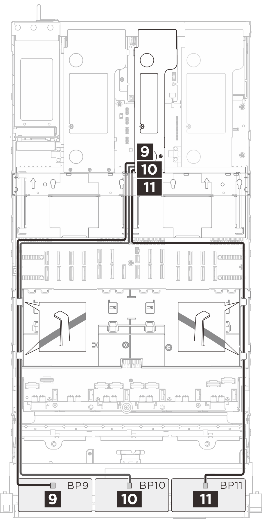 | 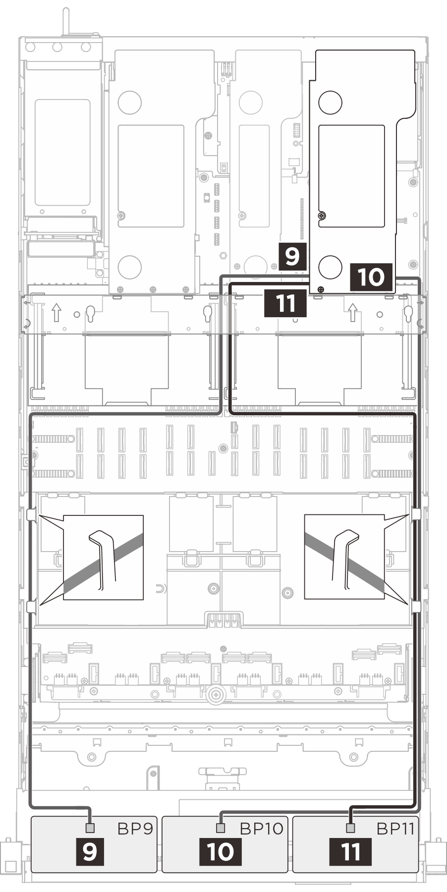 |
| Cable | From (backplane) | To (RAID/HBA adapter) |
|---|---|---|
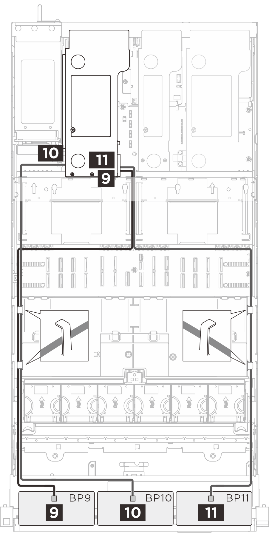
| SlimSAS x8 to SlimSAS x8 (1020 mm) | 9 BP 9: SAS | 9 RAID/HBA 8i/16i |
| SlimSAS x8 to SlimSAS x8 (1020 mm) | 10 BP 10: SAS | 10 RAID/HBA 8i/16i |
| SlimSAS x8 to SlimSAS x8 (1020 mm) | 11 BP 11: SAS | 11 RAID/HBA 8i/16i |