Instradamento dei cavi del backplane E3.S
Utilizzare questa sezione per comprendere l'instradamento dei cavi per i backplane E3.S.
Quando si instradano i cavi, verificare che tutti i cavi siano instradati correttamente attraverso le guide dei cavi e i fermacavi corrispondenti.
Numerazione dei backplane
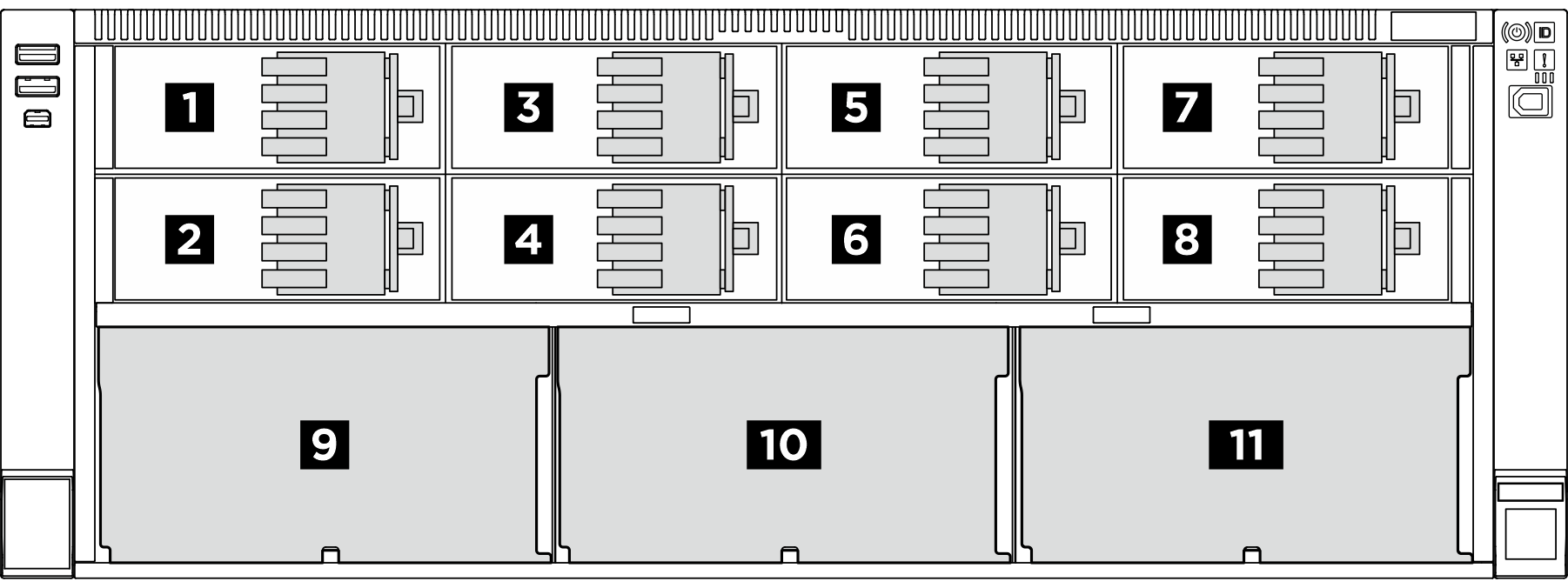
| Backplane dell'unità | Vano E3.S 1T | Vano E3.S 2T | Vano SAS/SATA da 2,5 pollici |
|---|---|---|---|
| 1 Backplane 1 | Da 0 a 3 | 1, 3 | |
| 2 Backplane 2 | Da 4 a 7 | 5, 7 | |
| 3 Backplane 3 | Da 8 a 11 | 9, 11 | |
| 4 Backplane 4 | Da 12 a 15 | 13, 15 | |
| 5 Backplane 5 | Da 16 a 19 | 17, 19 | |
| 6 Backplane 6 | Da 20 a 23 | 21, 23 | |
| 7 Backplane 7 | Da 24 a 27 | 25, 27 | |
| 8 Backplane 8 | Da 28 a 31 | 29, 31 | |
| 9 Backplane 9 | Da 32 a 39 | ||
| 10 Backplane 10 | Da 40 a 47 | ||
| 11 Backplane 11 | Da 48 a 55 |
I vani E3.S 1T supportano le unità E3.S 1T.
I vani E3.S 2T supportano i moduli di memoria CXL (CMM).
| Tipo di backplane | Priorità di posizionamento dei backplane |
|---|---|
| Backplane E3.S per i vani E3.S 1T | 1+2, 1+2+3+4, 1+2+3+4+5+6, 1+2+3+4+5+6+7+8 |
| Backplane E3.S per i vani E3.S 2T | 1+2+3+4+5+6+7+8 |
| Backplane dell'unità a 8 vani SAS/SATA da 2,5 pollici | 9, 10, 11 |
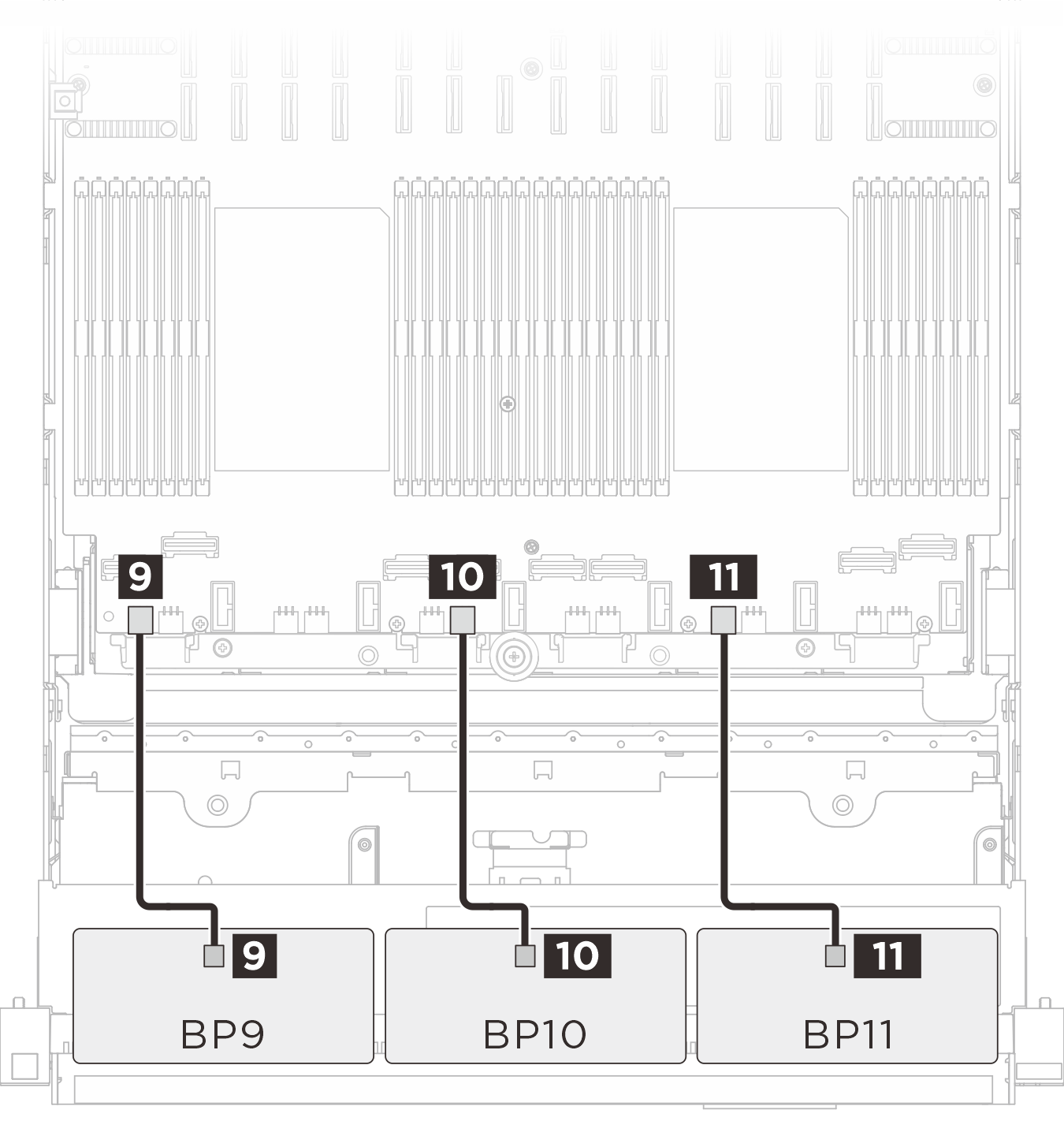
Instradamento dei cavi di alimentazione
| Instradamento dei cavi di alimentazione del backplane E3.S | Instradamento dei cavi di alimentazione del backplane SAS/SATA |
|---|---|
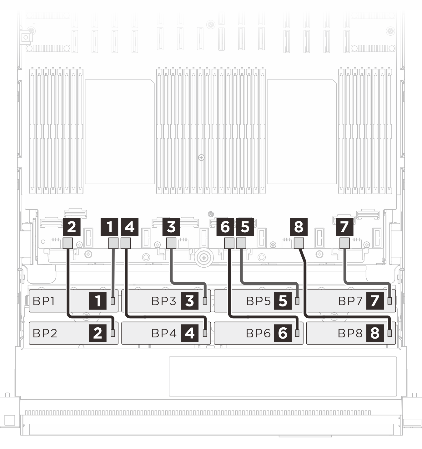 |  |
| Cavo | Da (backplane) | A (assieme della scheda di sistema) |
|---|---|---|
| MPIC 6p+6s to MPIC 6p+6s (230 mm) | 1 BP 1: PWR | 1 BP 3 PWR |
| MPIC 6p+6s to MPIC 6p+6s (230 mm) | 2 BP 2: PWR | 2 BP 2 PWR |
| MPIC 6p+6s to MPIC 6p+6s (230 mm) | 3 BP 3: PWR | 3 BP 5 PWR |
| MPIC 6p+6s to MPIC 6p+6s (230 mm) | 4 BP 4: PWR | 4 BP 4 PWR |
| MPIC 6p+6s to MPIC 6p+6s (230 mm) | 5 BP 5: PWR | 5 BP 8 PWR |
| MPIC 6p+6s to MPIC 6p+6s (230 mm) | 6 BP 6: PWR | 6 BP 7 PWR |
| MPIC 6p+6s to MPIC 6p+6s (230 mm) | 7 BP 7: PWR | 7 BP 11: PWR |
| MPIC 6p+6s to MPIC 6p+6s (230 mm) | 8 BP 8: PWR | 8 BP 10: PWR |
| MPIC 6p+6s to MPIC 6p+6s (150 mm) | 9 BP 9: PWR | 9 BP 1: PWR |
| MPIC 6p+6s to MPIC 6p+6s (150 mm) | 10 BP 10: PWR | 10 BP 6: PWR |
| MPIC 6p+6s to MPIC 6p+6s (150 mm) | 11 BP 11: PWR | 11 BP 9: PWR |
Instradamento dei cavi di segnale E3.S 1T
| Instradamento dei cavi di segnale BP1/BP2 | Instradamento dei cavi di segnale BP3/BP4 |
|---|---|
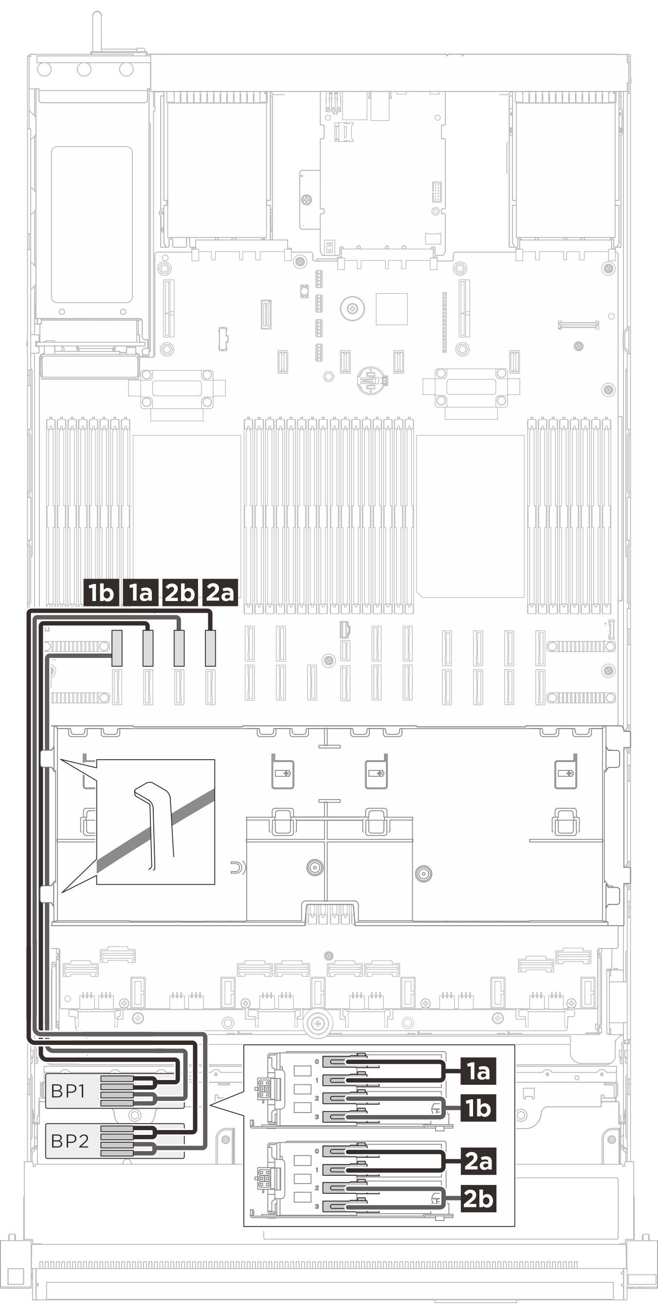 |  |
| Cavo | Da (backplane) | A (assieme della scheda di sistema) |
|---|---|---|
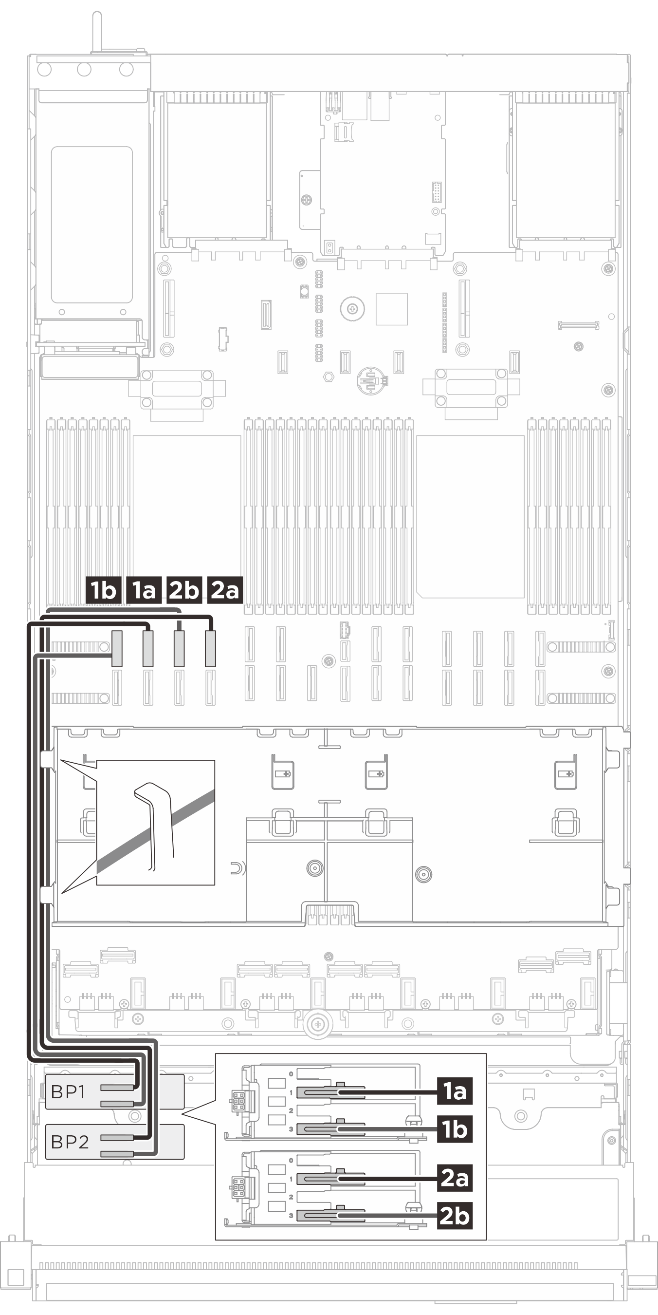
| MCIO x8 to Gen-Z 1C*2 (560 mm) | 1a BP 1: Bay 0, Bay 1 | 1a NVMe 10 |
| MCIO x8 to Gen-Z 1C*2 (560 mm) | 1b BP 1: Bay 2, Bay 3 | 1b NVMe 9 |
| MCIO x8 to Gen-Z 1C*2 (560 mm) | 2a BP 2: Bay 0, Bay 1 | 2a NVMe 14 |
| MCIO x8 to Gen-Z 1C*2 (560 mm) | 2b BP 2: Bay 2, Bay 3 | 2b NVMe 13 |
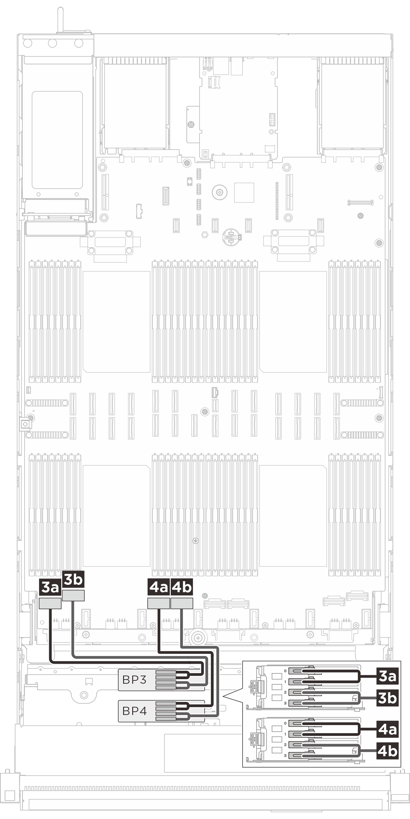
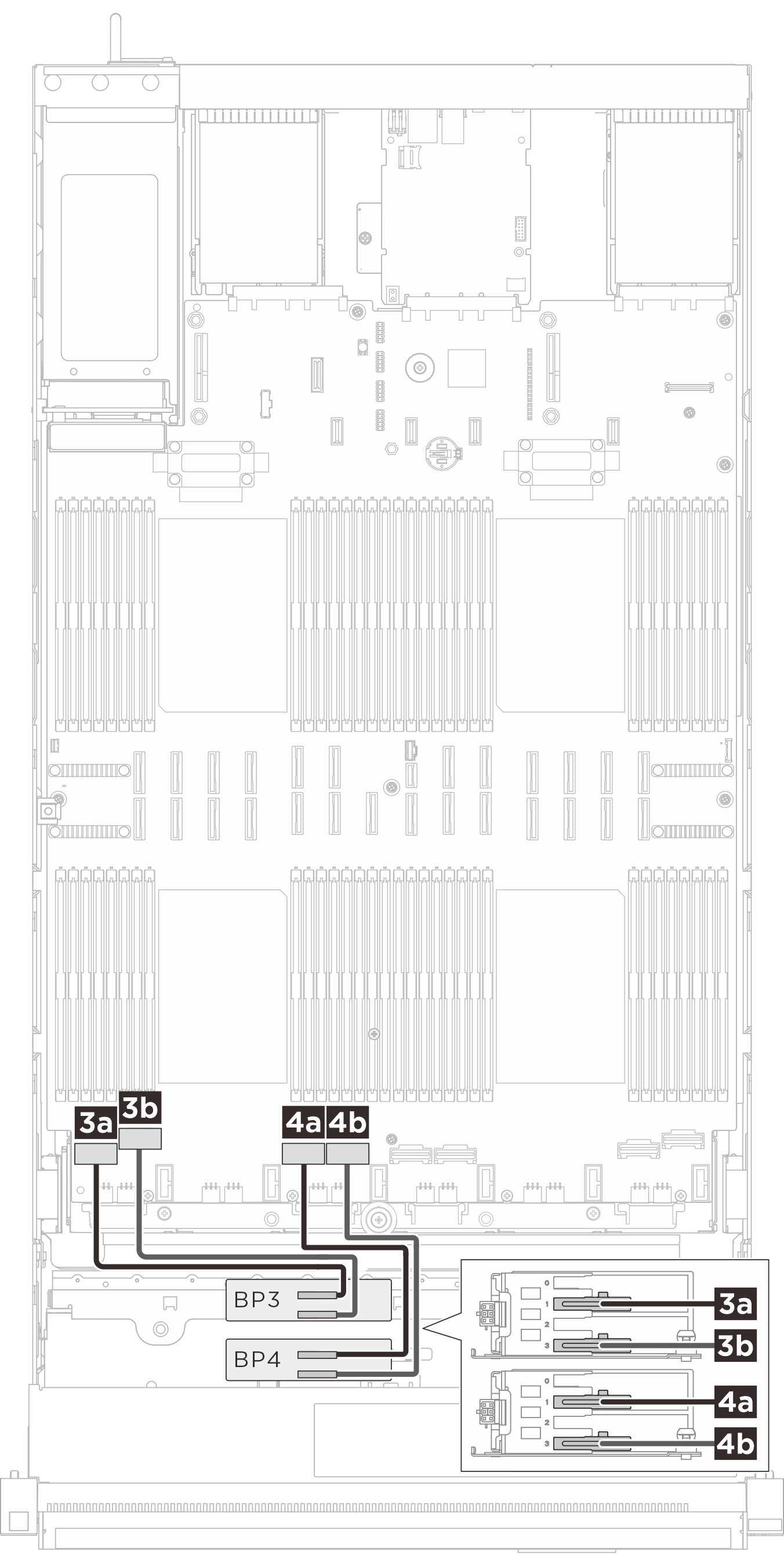
| Swift x8 to Gen-Z 1C*2 (330 mm) | 3a BP 3: Bay 0, Bay 1 | 3a NVMe 1 |
| Swift x8 to Gen-Z 1C*2 (330 mm) | 3b BP 3: Bay 2, Bay 3 | 3b NVMe 2 |
| Swift x8 to Gen-Z 1C*2 (330 mm) | 4a BP 4: Bay 0, Bay 1 | 4a NVMe 3 |
| Swift x8 to Gen-Z 1C*2 (330 mm) | 4b BP 4: Bay 2, Bay 3 | 4b NVMe 4 |
| Instradamento dei cavi di segnale BP5/BP6 | Instradamento dei cavi di segnale BP7/BP8 |
|---|---|
 |  |
| Cavo | Da (backplane) | A (assieme della scheda di sistema) |
|---|---|---|
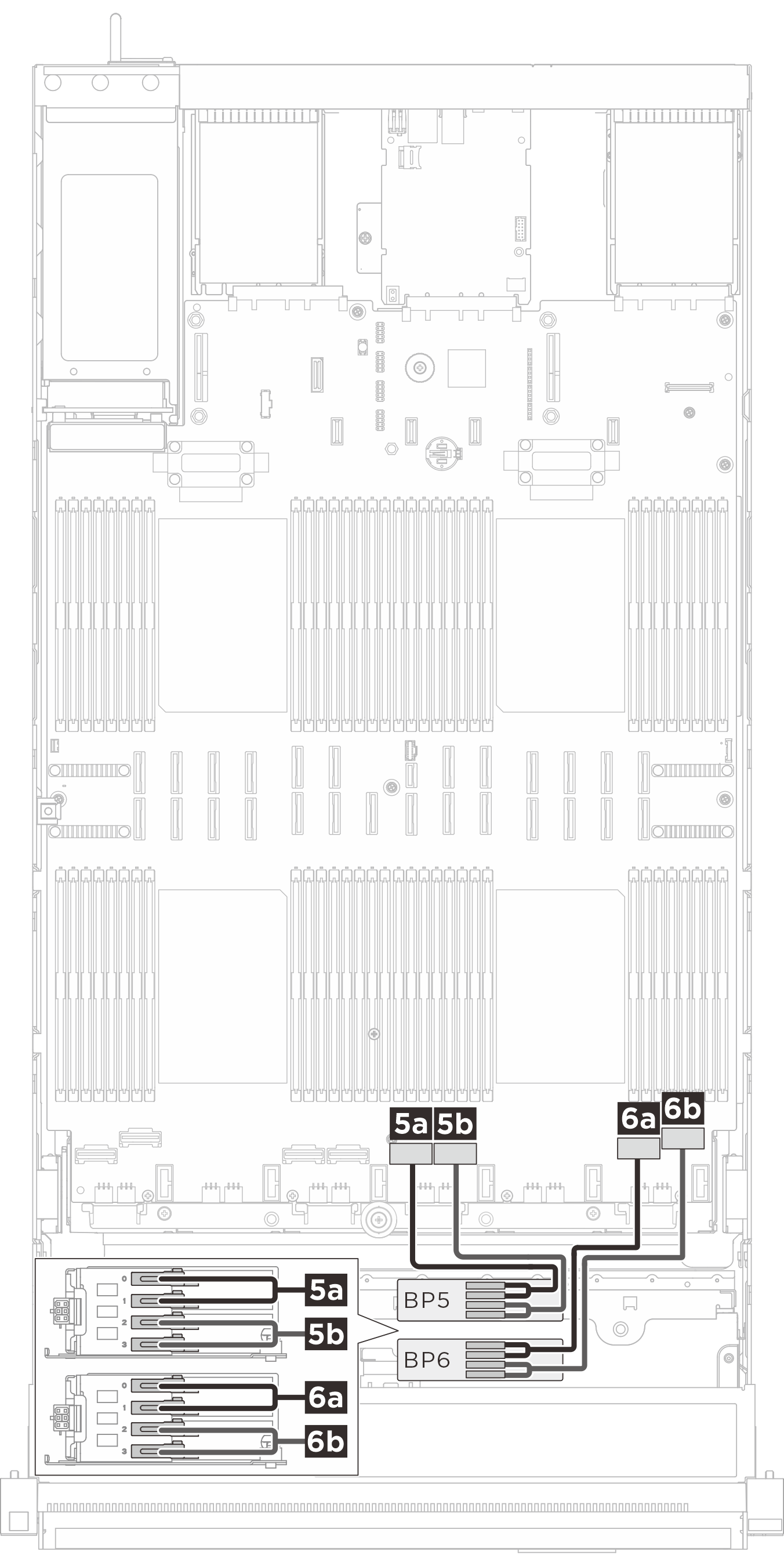
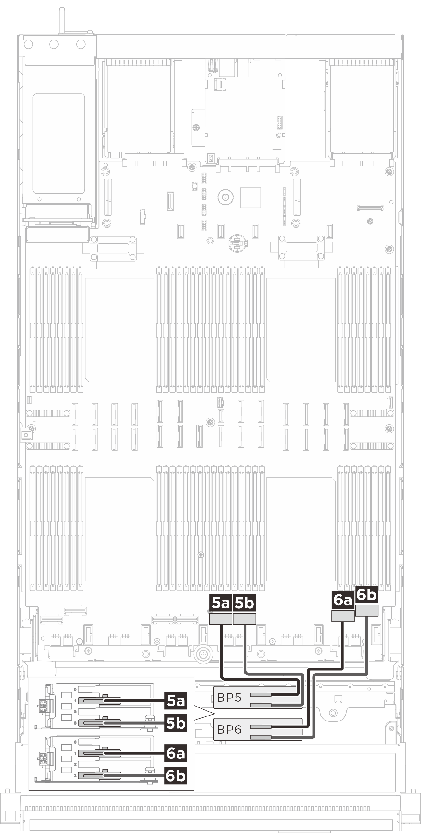
| Swift x8 to Gen-Z 1C*2 (330 mm) | 5a BP 5: Bay 0, Bay 1 | 5a NVMe 5 |
| Swift x8 to Gen-Z 1C*2 (330 mm) | 5b BP 5: Bay 2, Bay 3 | 5b NVMe 6 |
| Swift x8 to Gen-Z 1C*2 (330 mm) | 6a BP 6: Bay 0, Bay 1 | 6a NVMe 7 |
| Swift x8 to Gen-Z 1C*2 (330 mm) | 6b BP 6: Bay 2, Bay 3 | 6b NVMe 8 |
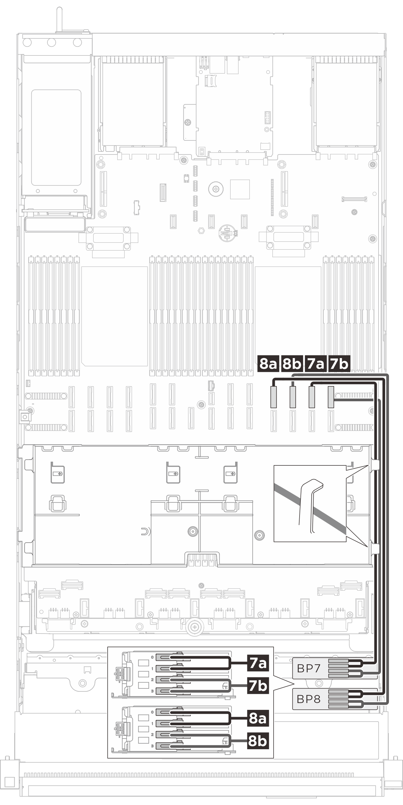
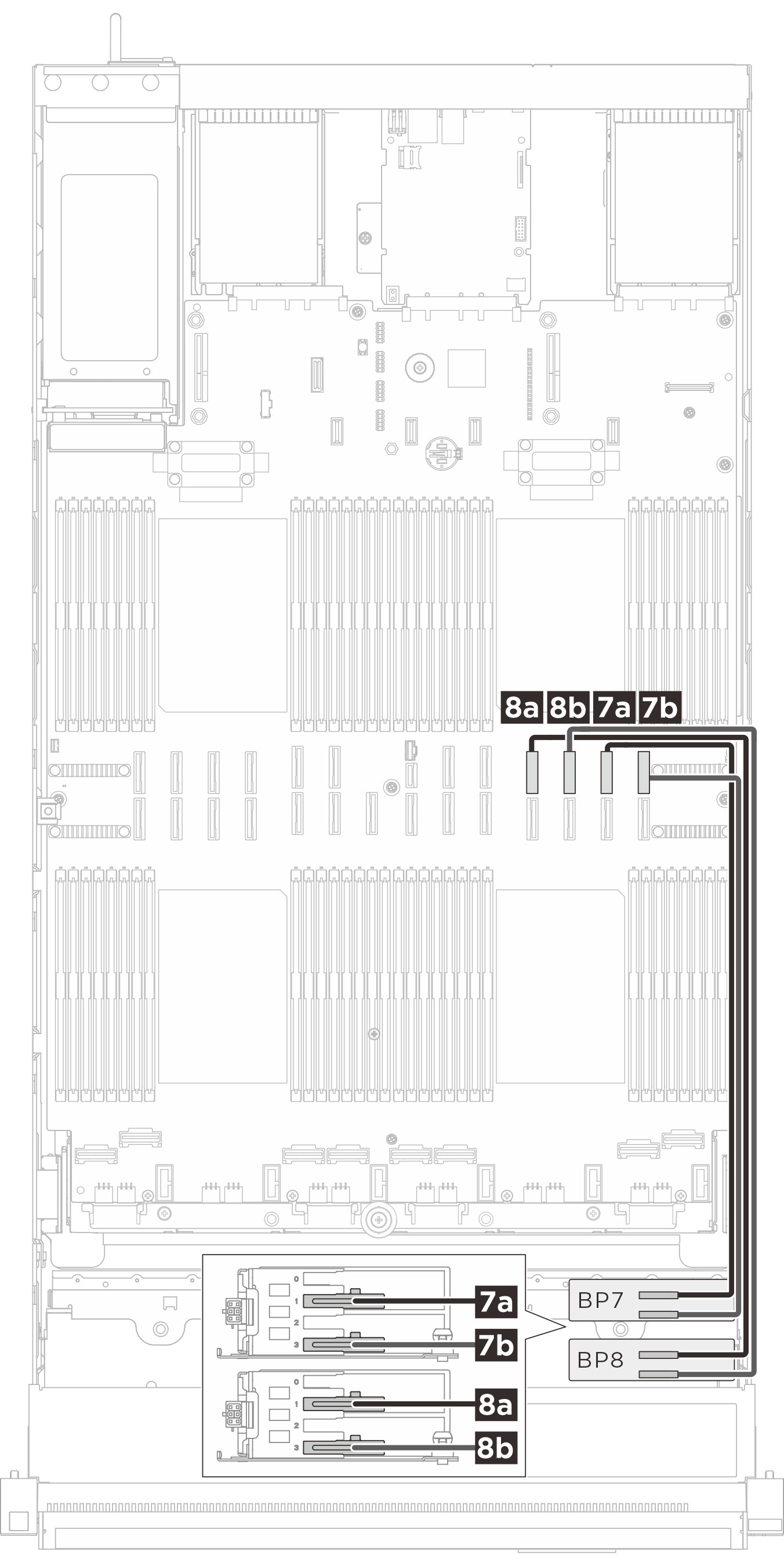
| MCIO x8 to Gen-Z 1C*2 (560 mm) | 7a BP 7: Bay 0, Bay 1 | 7a NVMe 11 |
| MCIO x8 to Gen-Z 1C*2 (560 mm) | 7b BP 7: Bay 2, Bay 3 | 7b NVMe 12 |
| MCIO x8 to Gen-Z 1C*2 (560 mm) | 8a BP 8: Bay 0, Bay 1 | 8a NVMe 15 |
| MCIO x8 to Gen-Z 1C*2 (560 mm) | 8b BP 8: Bay 2, Bay 3 | 8b NVMe 16 |
Instradamento dei cavi di segnale E3.S 2T
| Instradamento dei cavi di segnale BP1/BP2 | Instradamento dei cavi di segnale BP3/BP4 |
|---|---|
 |  |
| Cavo | Da (backplane) | A (assieme della scheda di sistema) |
|---|---|---|
| MCIO x8 to Gen-Z 2C (560 mm) | 1a BP 1: Bay 1 | 1a NVMe 10 |
| MCIO x8 to Gen-Z 2C (560 mm) | 1b BP 1: Bay 3 | 1b NVMe 9 |
| MCIO x8 to Gen-Z 2C (560 mm) | 2a BP 2: Bay 1 | 2a NVMe 14 |
| MCIO x8 to Gen-Z 2C (560 mm) | 2b BP 2: Bay 3 | 2b NVMe 13 |
| Swift x8 to Gen-Z 2C (330 mm) | 3a BP 3: Bay 1 | 3a NVMe 1 |
| Swift x8 to Gen-Z 2C (330 mm) | 3b BP 3: Bay 3 | 3b NVMe 2 |
| Swift x8 to Gen-Z 2C (330 mm) | 4a BP 4: Bay 1 | 4a NVMe 3 |
| Swift x8 to Gen-Z 2C (330 mm) | 4b BP 4: Bay 3 | 4b NVMe 4 |
| Instradamento dei cavi di segnale BP5/BP6 | Instradamento dei cavi di segnale BP7/BP8 |
|---|---|
 |  |
| Cavo | Da (backplane) | A (assieme della scheda di sistema) |
|---|---|---|
| Swift x8 to Gen-Z 2C (330 mm) | 5a BP 5: Bay 1 | 5a NVMe 5 |
| Swift x8 to Gen-Z 2C (330 mm) | 5b BP 5: Bay 3 | 5b NVMe 6 |
| Swift x8 to Gen-Z 2C (330 mm) | 6a BP 6: Bay 1 | 6a NVMe 7 |
| Swift x8 to Gen-Z 2C (330 mm) | 6b BP 6: Bay 3 | 6b NVMe 8 |
| MCIO x8 to Gen-Z 2C (560 mm) | 7a BP 7: Bay 1 | 7a NVMe 11 |
| MCIO x8 to Gen-Z 2C (560 mm) | 7b BP 7: Bay 3 | 7b NVMe 12 |
| MCIO x8 to Gen-Z 2C (560 mm) | 8a BP 8: Bay 1 | 8a NVMe 15 |
| MCIO x8 to Gen-Z 2C (560 mm) | 8b BP 8: Bay 3 | 8b NVMe 16 |
Instradamento dei cavi di segnale del backplane SAS/SATA
Adattatori RAID/HBA Gen 4: 545-8i/940-8i/940-16i/440-16i
1 backplane: 1 x RAID/HBA 8i
2 backplane: 1 x RAID/HBA 16i
3 backplane: 1 x RAID/HBA 8i + 1 x RAID/HBA 16i
A seconda della configurazione, gli adattatori RAID/HBA saranno installati in schede verticali diverse. In base alla posizione dell'adattatore RAID/HBA selezionare il percorso di instradamento corrispondente dalla tabella seguente.
| Instradamento dei cavi per la scheda verticale 3 | Instradamento dei cavi per la scheda verticale 2 | Instradamento dei cavi per la scheda verticale 1 |
|---|---|---|
 | 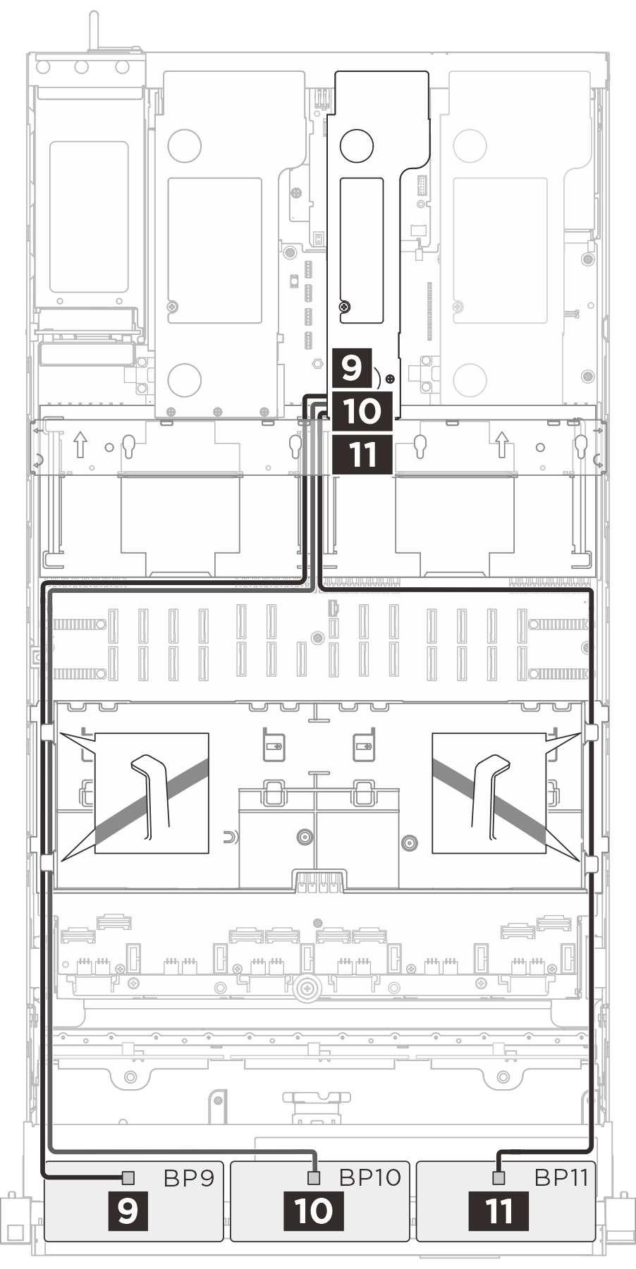 | 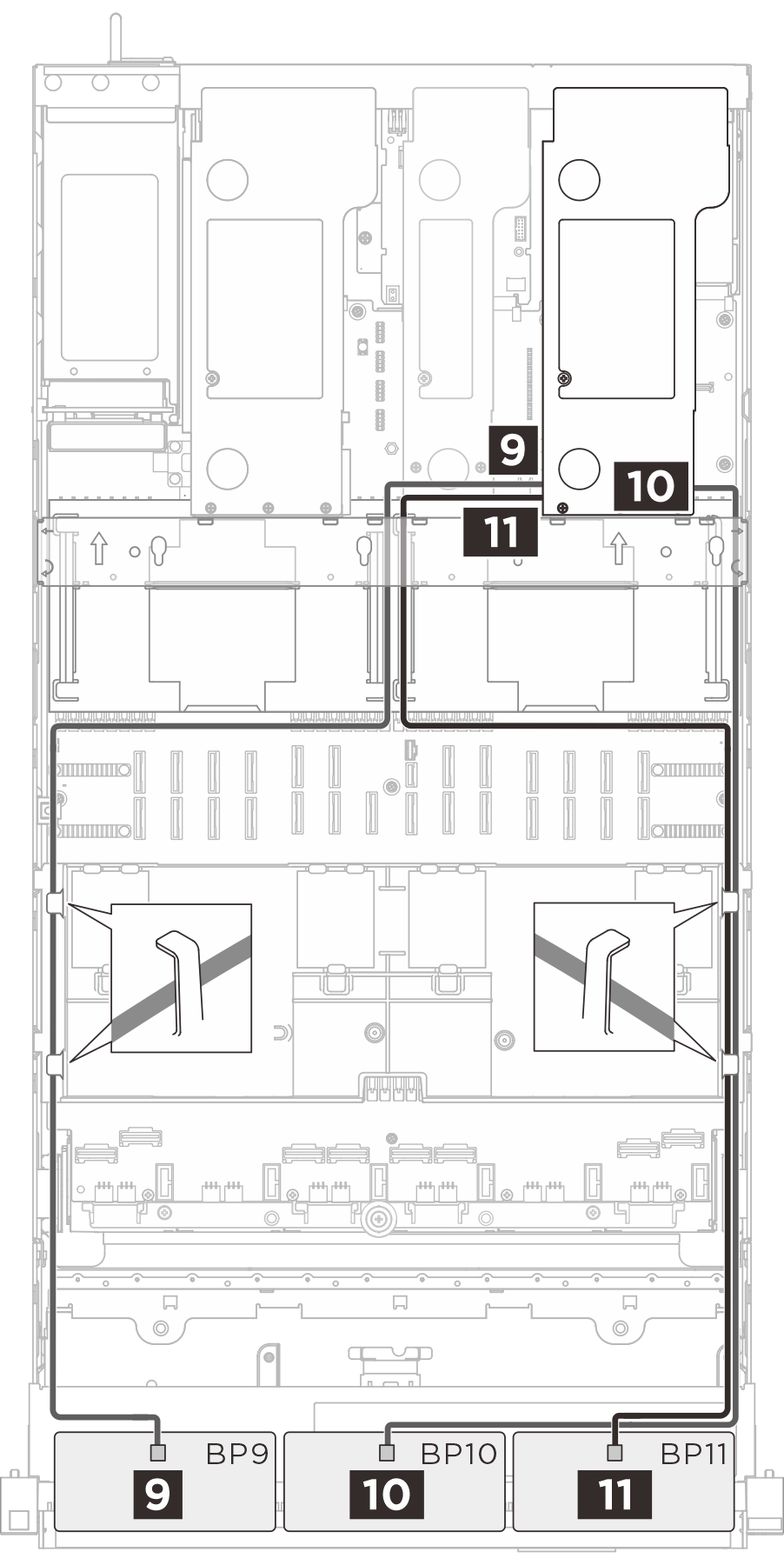 |
| Cavo | Da (backplane) | A (adattatore HBA/RAID) |
|---|---|---|
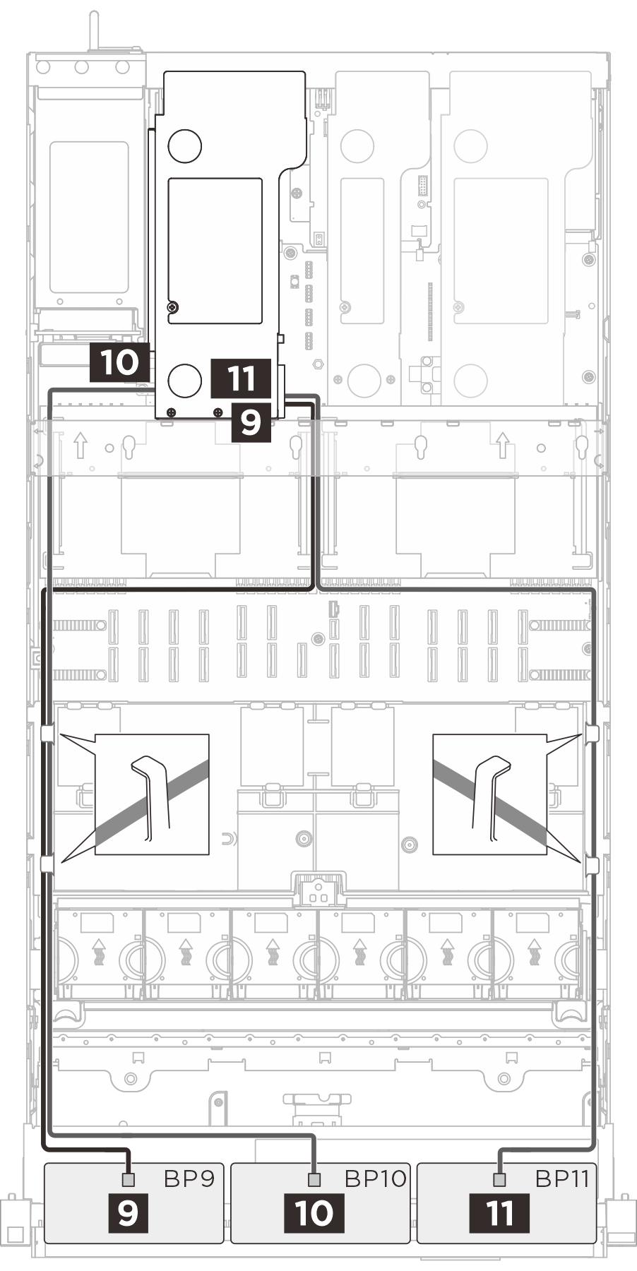
| SlimSAS x8 to SlimSAS x8 (1020 mm) | 9 BP 9: SAS | 9 RAID/HBA 8i/16i |
| SlimSAS x8 to SlimSAS x8 (1020 mm) | 10 BP 10: SAS | 10 RAID/HBA 8i/16i |
| SlimSAS x8 to SlimSAS x8 (1020 mm) | 11 BP 11: SAS | 11 RAID/HBA 8i/16i |