Install the H100/H200 GPU complex adapter plate
Follow instructions in this section to install the H100/H200 GPU complex adapter plate. The procedure must be executed by a trained technician.
About this task
Attention
- Read Installation Guidelines and Safety inspection checklist to ensure that you work safely.
- Touch the static-protective package that contains the component to any unpainted metal surface on the server; then, remove it from the package and place it on a static-protective surface.
Note
Make sure you have the required tools listed below available to properly replace the component:
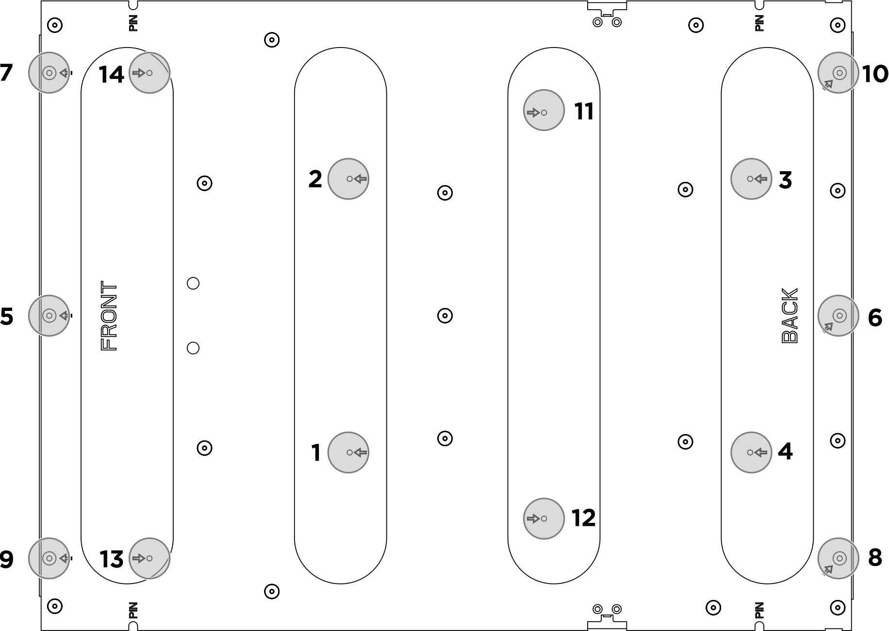
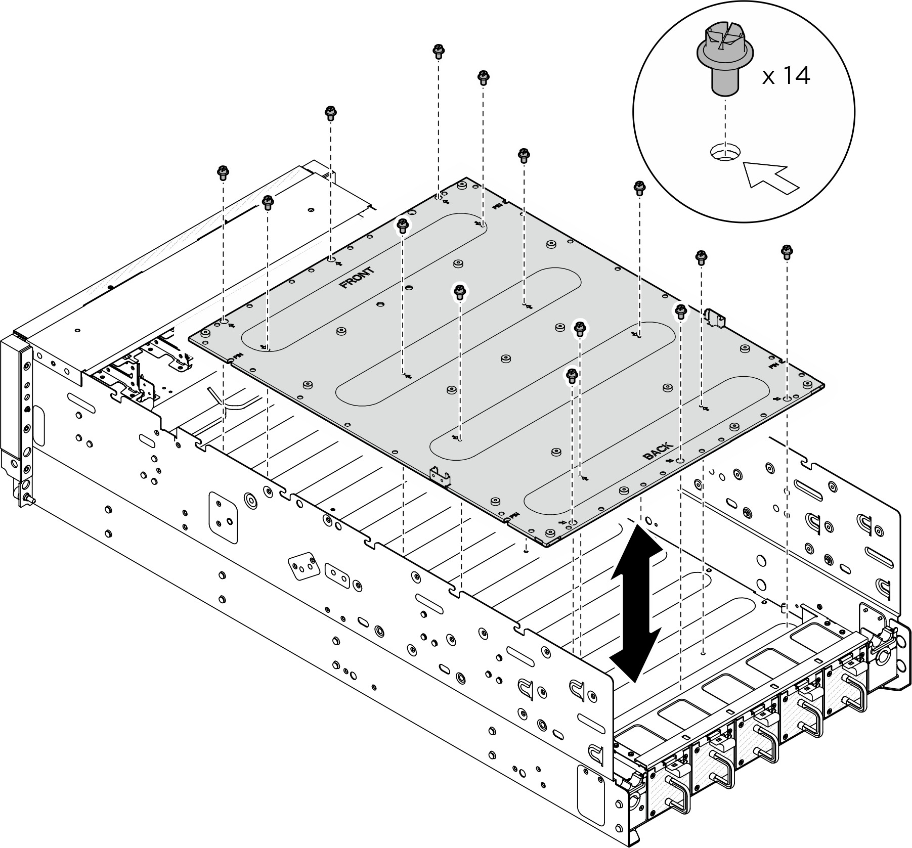
- Torque screwdriver which can be set to 0.6 newton-meters, 5.3 inch-pounds (for GPU complex).
Procedure
After you finish
- Reinstall the NVSwitch cold plate module. SeeInstall the H100/H200 NVSwitch cold plate module.
- Reinstall the front GPU cold plate module. See Install the front H100/H200 GPU cold plate module.
- Reinstall the rear GPU cold plate module. See Install the rear H100/H200 GPU cold plate module.
- Reconnect the cables to the GPU baseboard. See GPU baseboard cable routing for more information.
- Reconnect all the cables that were disconnected. See Internal cable routing.
- Reinstall the power complex. See Install the power complex.
- Reinstall the CPU complex. See Install the CPU complex.
- Reinstall the fan cage. See Install the fan cage (trained technician only).
- Reinstall the rear top cover. See Install the rear top cover.
- Reinstall the front top cover. See Install the front top cover.
- Complete the parts replacement. See Complete the parts replacement.
Give documentation feedback


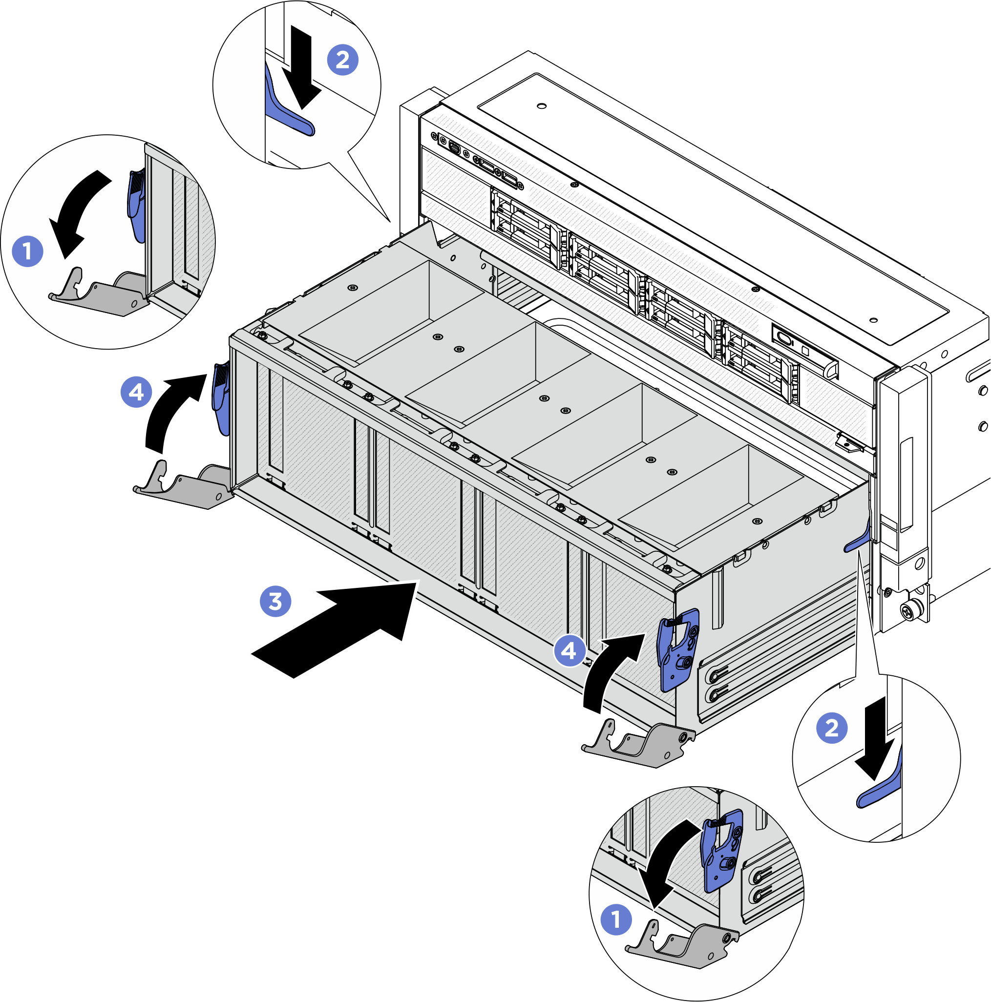
 Press the two blue release latches.
 Press the two lock latches on both sides of the PCIe switch shuttle.
 Push the PCIe switch shuttle into the chassis until it stops.
 Rotate the two release levers until they lock into place.