Kabelführung der Rückwandplatine für 2,5-Zoll-Laufwerke
Verwenden Sie diesen Abschnitt, um die Kabelführung für die Rückwandplatine für 2,5-Zoll-Laufwerke zu verstehen.
Verbindungen zwischen Anschlüssen: 1↔1, 2↔2, 3↔3, … n↔n
Die Cable PN oder FRU PN finden Sie auf dem Etikett, das am Kabel befestigt ist.
Stellen Sie beim Verlegen der Kabel sicher, dass alle Kabel ordnungsgemäß durch die entsprechenden Kabelführungen und Kabelklemmen geführt werden.
In den Abbildungen in diesem Abschnitt wird ein HL PCIe-Adapterkarte als Beispiel für PCIe-Adapterkarte 1 und 3 verwendet. Die Kabelführung für den FL PCIe-Adapterkarte ist identisch.
AnyBay-Rückwandplatinen werden als NVMe-Rückwandplatinen verwendet, wenn keine RAID/HBA-Adapter installiert sind.
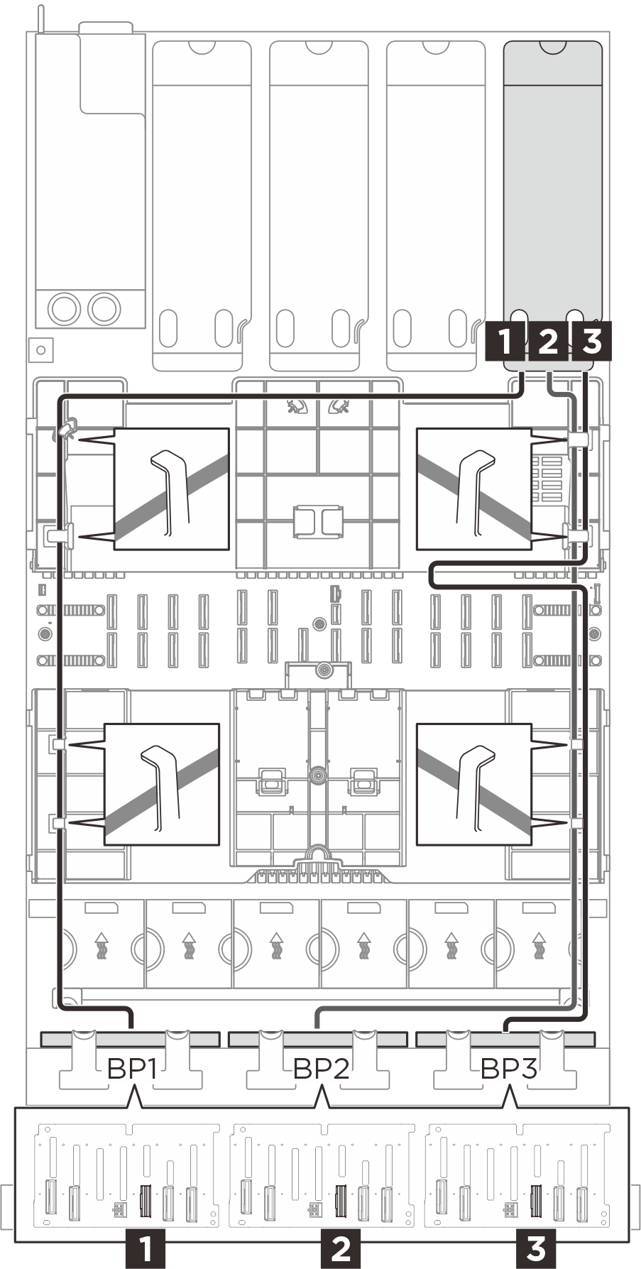
Netzkabelführung
 |
| Von (Rückwandplatine) | Zu (Systemplatinenbaugruppe) | Kabel |
|---|---|---|
1 BP1: PWR | 1 BP3 PWR | 6P+6S auf 6P+6S (150 mm) |
2 BP2: PWR | 2 BP5 PWR | 6P+6S auf 6P+6S (150 mm) |
3 BP3: PWR | 3 BP8 PWR | 6P+6S auf 6P+6S (150 mm) |
NVMe-Kabelführung
| BP1 NVMe-Kabelführung | BP2 NVMe-Kabelführung | BP3 NVMe-Kabelführung |
|---|---|---|
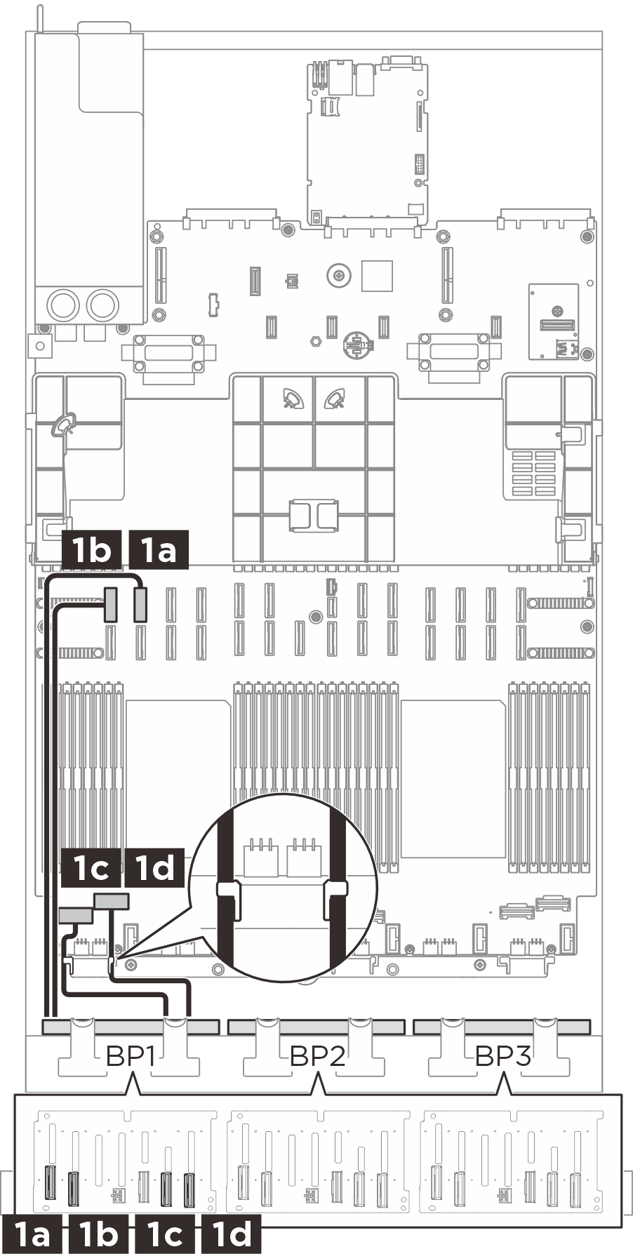 | 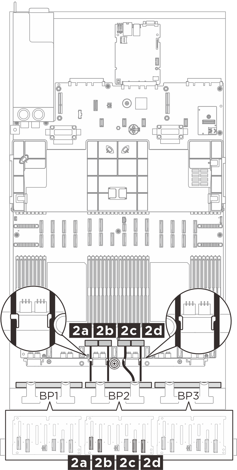 | 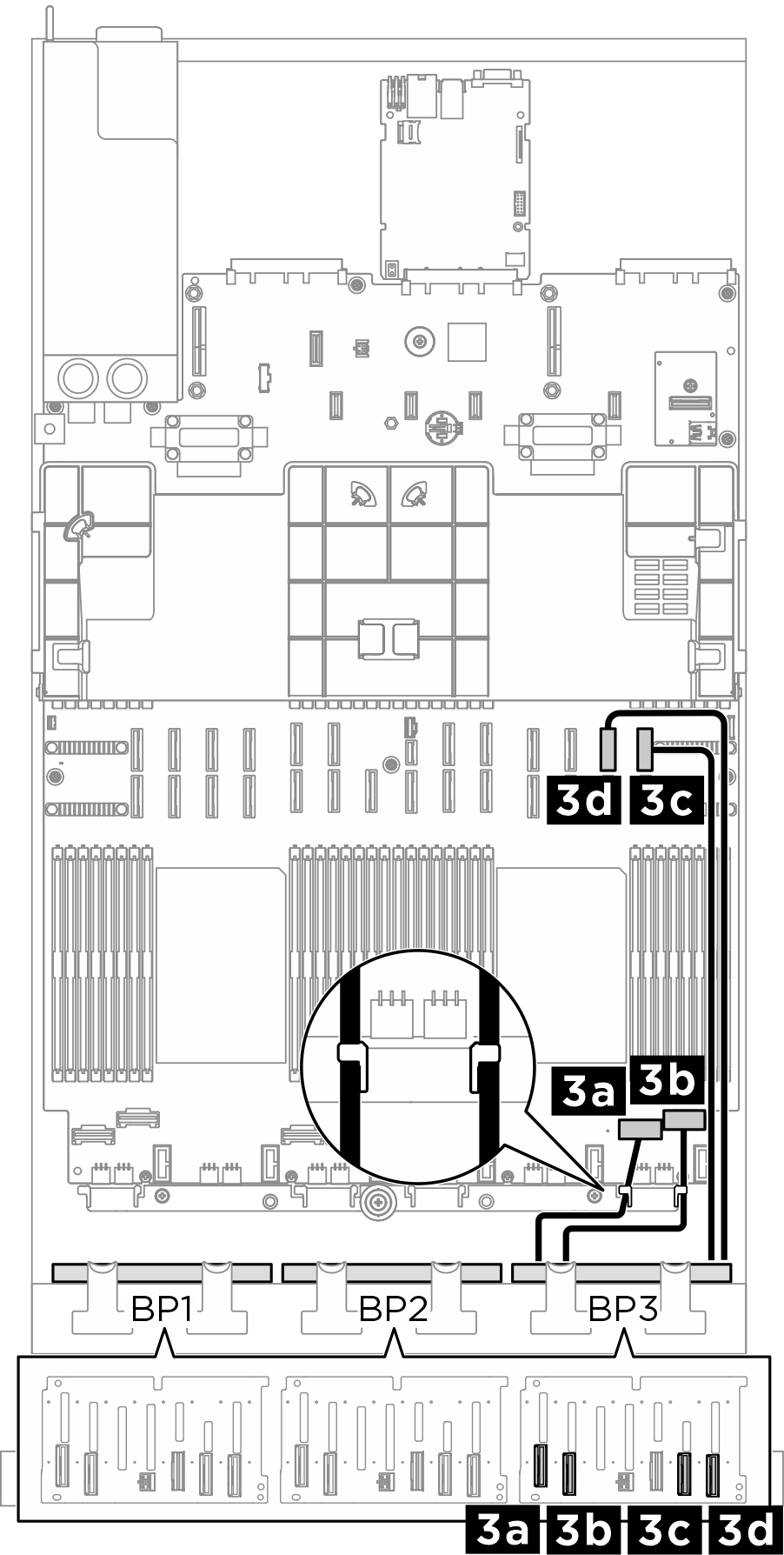 |
| Von (Rückwandplatine) | Zu (Systemplatinenbaugruppe) | Kabel |
|---|---|---|
| 1a BP1: NVMe 0-1 | 1a NVMe 10 | MCIO x8 auf MCIO x8 (420 mm) |
| 1b BP1: NVMe 2–3 | 1b NVMe 9 | MCIO x8 auf MCIO x8 (420 mm) |
| 1c BP1: NVMe 4–5 | 1c NVMe 1 | Swift x8 auf MCIO x8 (150 mm) |
| 1d BP1: NVMe 6–7 | 1d NVMe 2 | Swift x8 auf MCIO x8 (150 mm) |
| 2a BP2: NVMe 0–1 | 2a NVMe 3 | Swift x8 auf MCIO x8 (150 mm) |
| 2b BP2: NVMe 2–3 | 2b NVMe 4 | Swift x8 auf MCIO x8 (150 mm) |
| 2c BP2: NVMe 4–5 | 2c NVMe 5 | Swift x8 auf MCIO x8 (150 mm) |
| 2d BP2: NVMe 6–7 | 2d NVMe 6 | Swift x8 auf MCIO x8 (150 mm) |
| 3a BP3: NVMe 0–1 | 3a NVMe 7 | Swift x8 auf MCIO x8 (150 mm) |
| 3b BP3: NVMe 2–3 | 3b NVMe 8 | Swift x8 auf MCIO x8 (150 mm) |
| 3c BP3: NVMe 4–5 | 3c NVMe 12 | MCIO x8 auf MCIO x8 (420 mm) |
| 3d BP3: NVMe 6–7 | 3d NVMe 11 | MCIO x8 auf MCIO x8 (420 mm) |
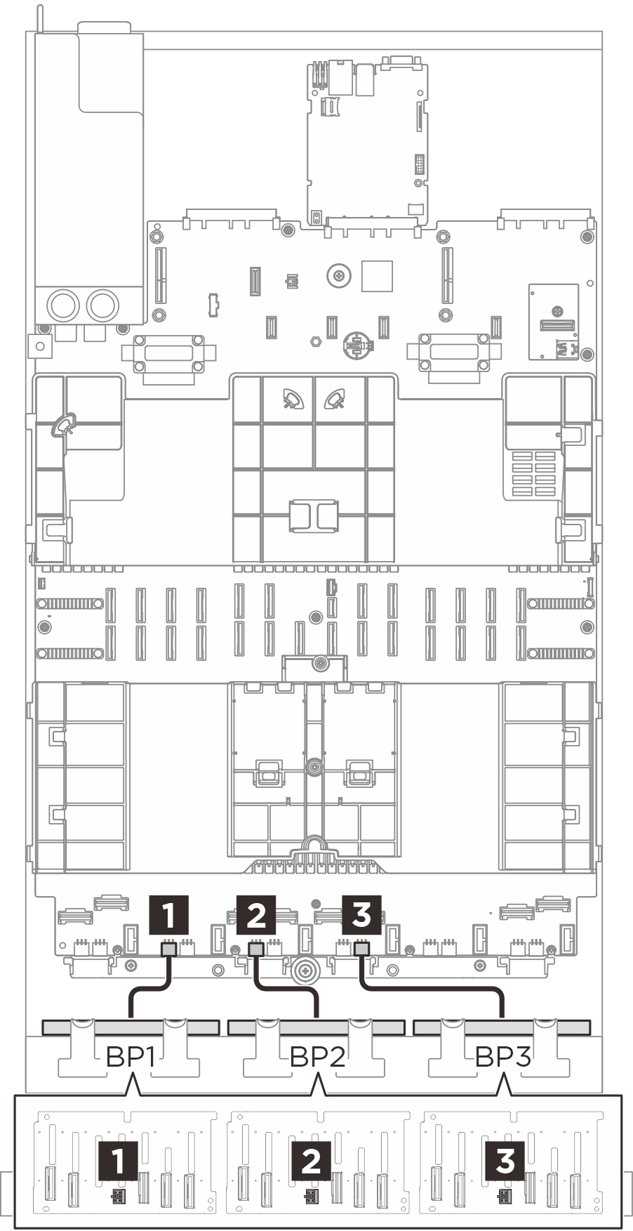
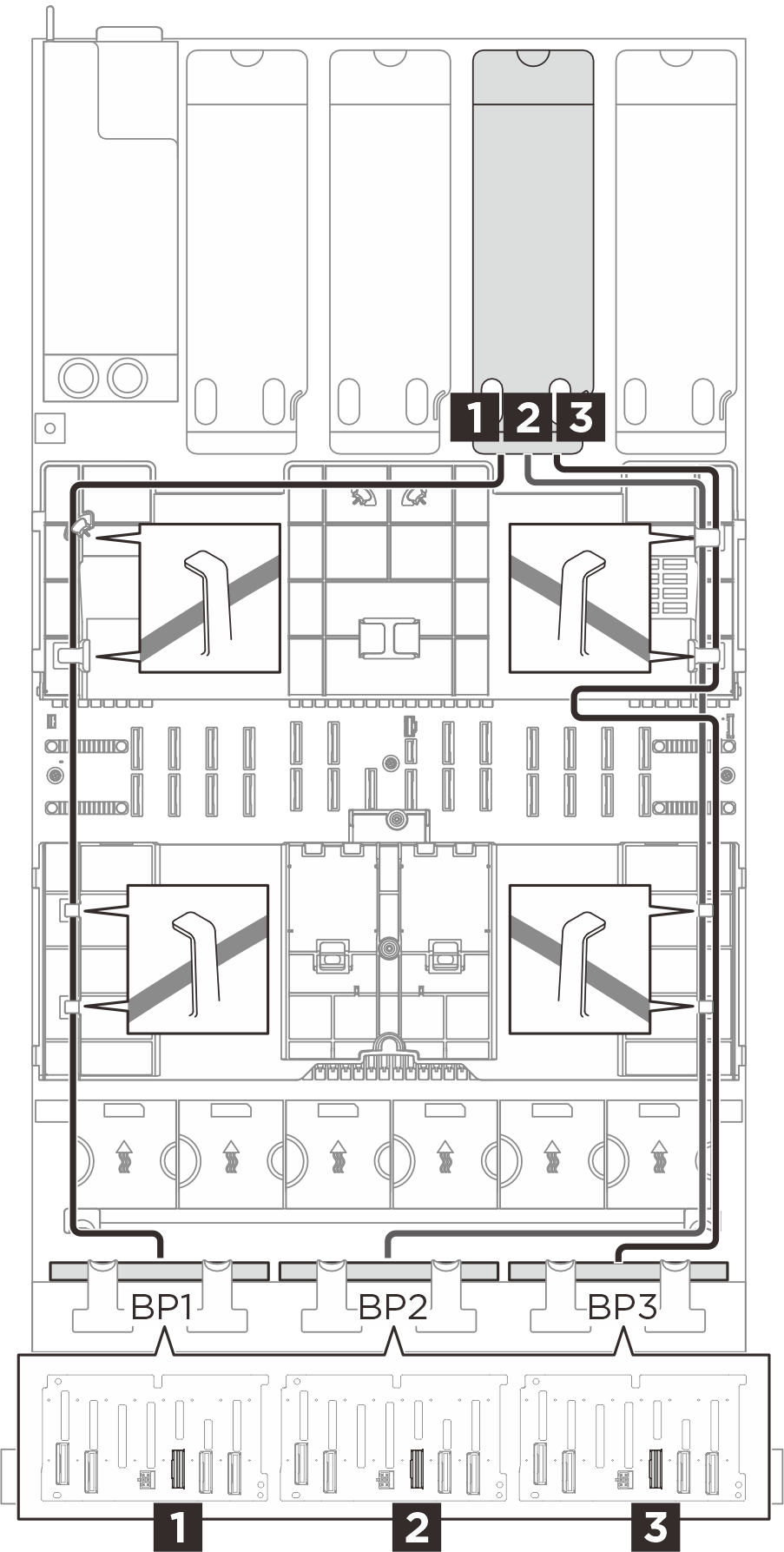
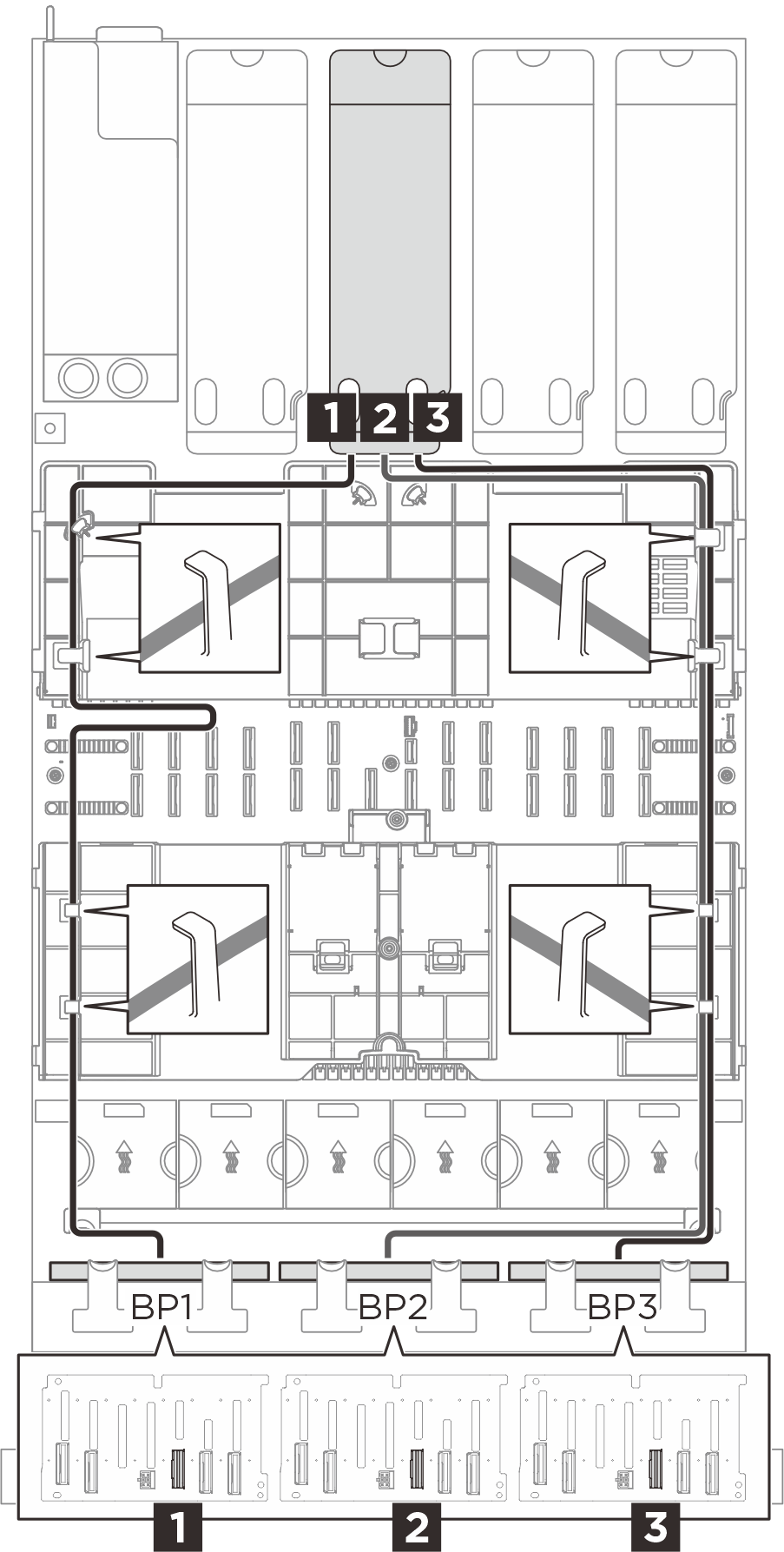
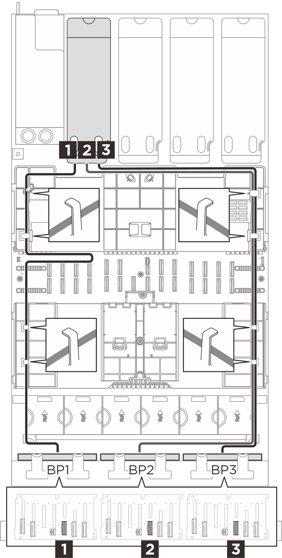
SAS/SATA Kabelführung (drei Adapterkarten)
Wählen Sie basierend auf der Position des Adapters den entsprechenden Kabelführungsplan für SAS/SATA-Kabel aus der folgenden Tabelle aus.
| SAS/SATA-Kabelführung zu Adapterkarte 3 | SAS/SATA-Kabelführung zu Adapterkarte 2 | SAS/SATA-Kabelführung zu Adapterkarte 1 |
|---|---|---|
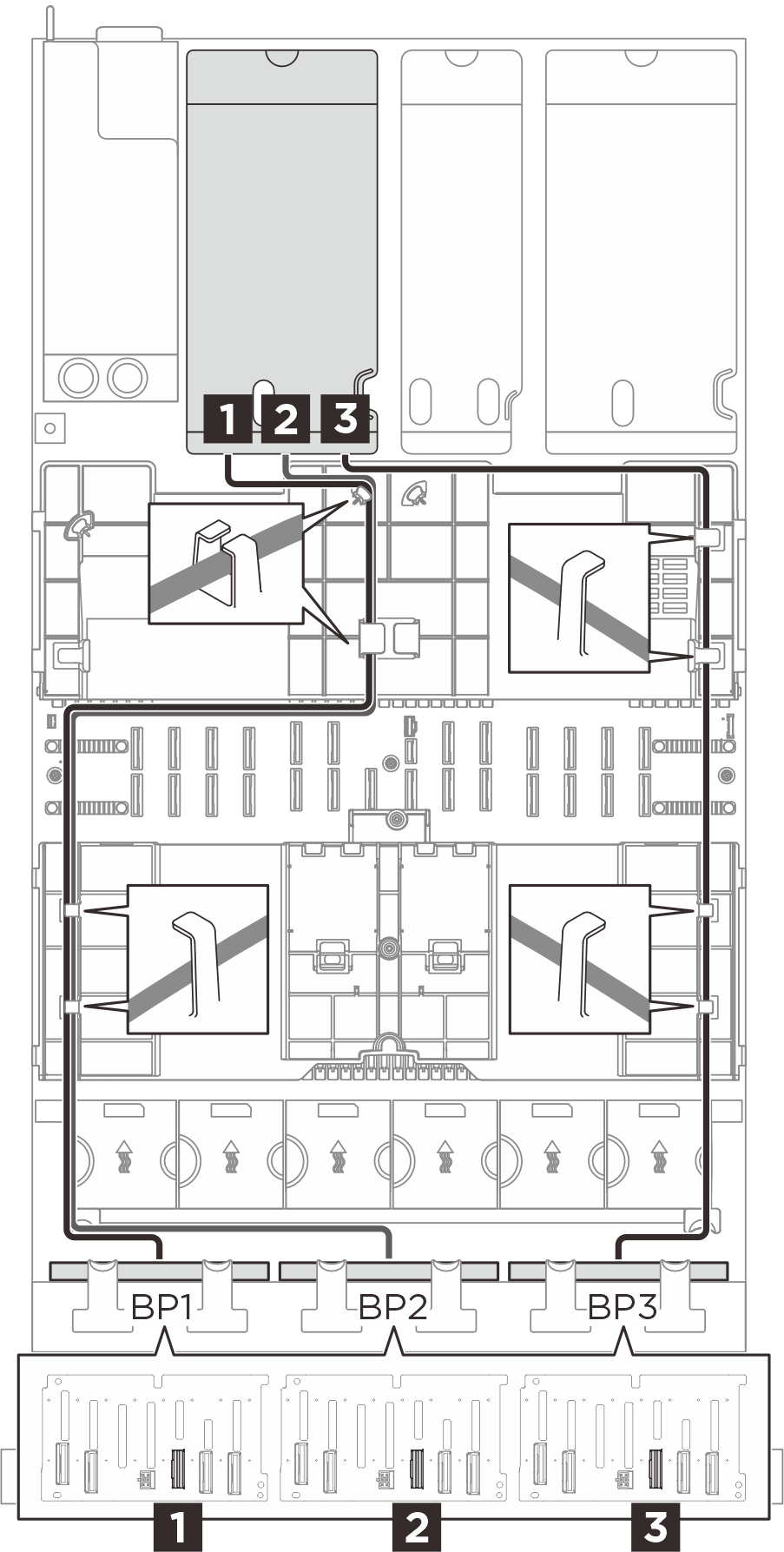 | 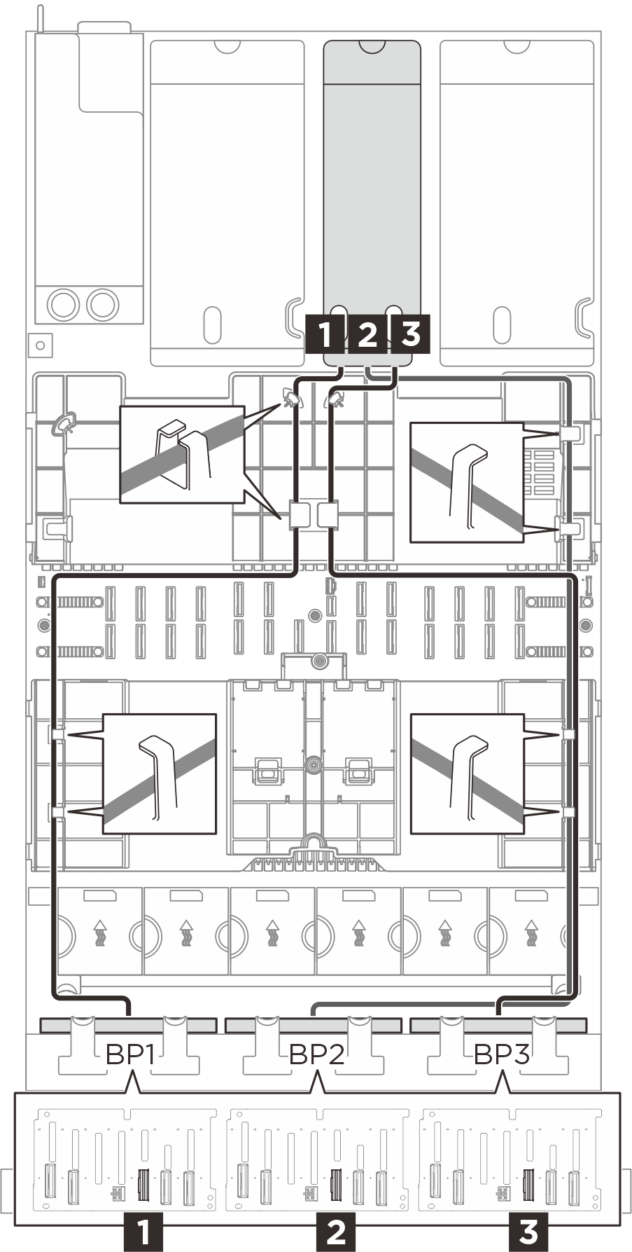 | 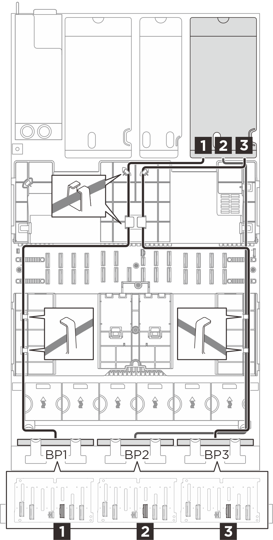 |
| Von (Rückwandplatine) | Zu (RAID/HBA-Adapter) | Kabel |
|---|---|---|
| 1 BP1: SAS | 1
| SlimSAS x8 auf SlimSAS x8 (1.020 mm) |
| 2 BP2: SAS | 2
| SlimSAS x8 auf SlimSAS x8 (1.020 mm) |
| 3 BP3: SAS | 3
| SlimSAS x8 auf SlimSAS x8 (1.020 mm) |
SAS/SATA Kabelführung (vier Adapterkarten)
Wählen Sie basierend auf der Position des Adapters den entsprechenden Kabelführungsplan für SAS/SATA-Kabel aus der folgenden Tabelle aus.
| SAS/SATA Kabelführung zu Adapterkarte A | SAS/SATA Kabelführung zu Adapterkarte B |
|---|---|
 |  |
| SAS/SATA Kabelführung zu Adapterkarte C | SAS/SATA Kabelführung zu Adapterkarte D |
 |  |
| Von (Rückwandplatine) | Zu (RAID/HBA-Adapter) | Kabel |
|---|---|---|
| 1 BP1: SAS | 1
| SlimSAS x8 auf SlimSAS x8 (1.020 mm) |
| 2 BP2: SAS | 2
| SlimSAS x8 auf SlimSAS x8 (1.020 mm) |
| 3 BP3: SAS | 3
| SlimSAS x8 auf SlimSAS x8 (1.020 mm) |