Remove the system I/O board and interposer board
Follow instructions in this section to remove the system I/O board and interposer board.
About this task
This task must be operated by trained technicians that are certified by Lenovo Service. Do not attempt to remove or install the part without proper training and qualification.
When disconnecting cables, make a list of each cable and record the connectors the cable is connected to, and use the record as a cabling checklist after installing the new system I/O board and interposer board.
Read Installation Guidelines and Safety inspection checklist to ensure that you work safely.
Power off the server and peripheral devices, disconnect the power cords from the primary chassis, then disconnect the power cords from the secondary chassis. See Power off the server.
Prevent exposure to static electricity, which might lead to system halt and loss of data, by keeping static-sensitive components in their static-protective packages until installation, and handling these devices with an electrostatic-discharge wrist strap or other grounding system.
If the server is installed in a rack, remove the server from the rack. See Remove the server from rails.
Procedure
- Disconnect the SCM cable.Figure 1. Disconnecting SCM cable
 Remove the two screws that secure the SCM cable.
 Disconnect the SCM cable from the interposer board.
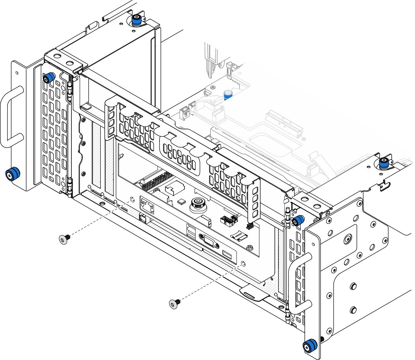
- Remove the two screws on the front of the chassis.Figure 2. Loosening system I/O board and interposer assembly
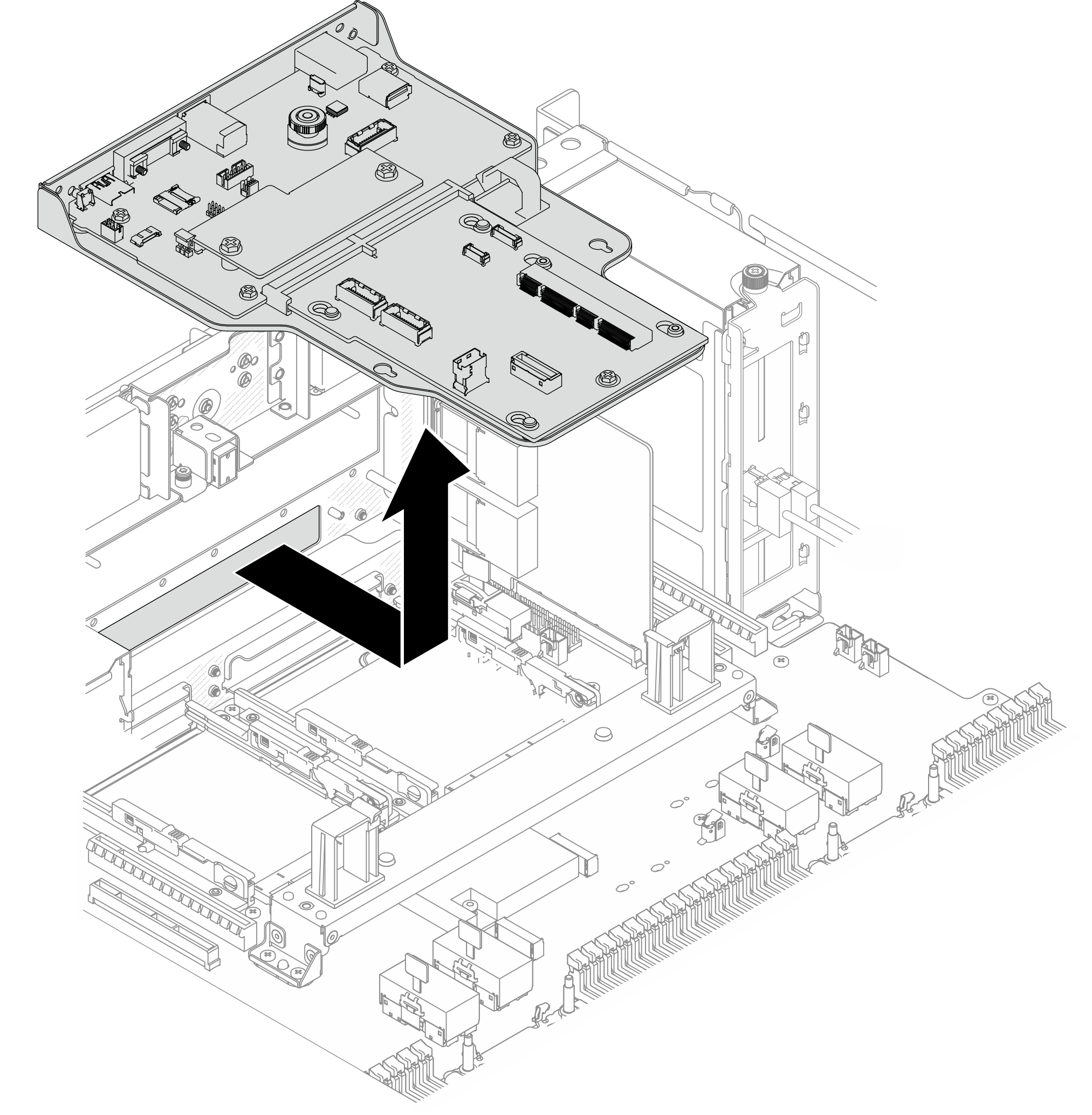
- Slide the system I/O board and interposer assembly towards the rear of the chassis to remove it.Figure 3. Removing system I/O board and interposer assembly
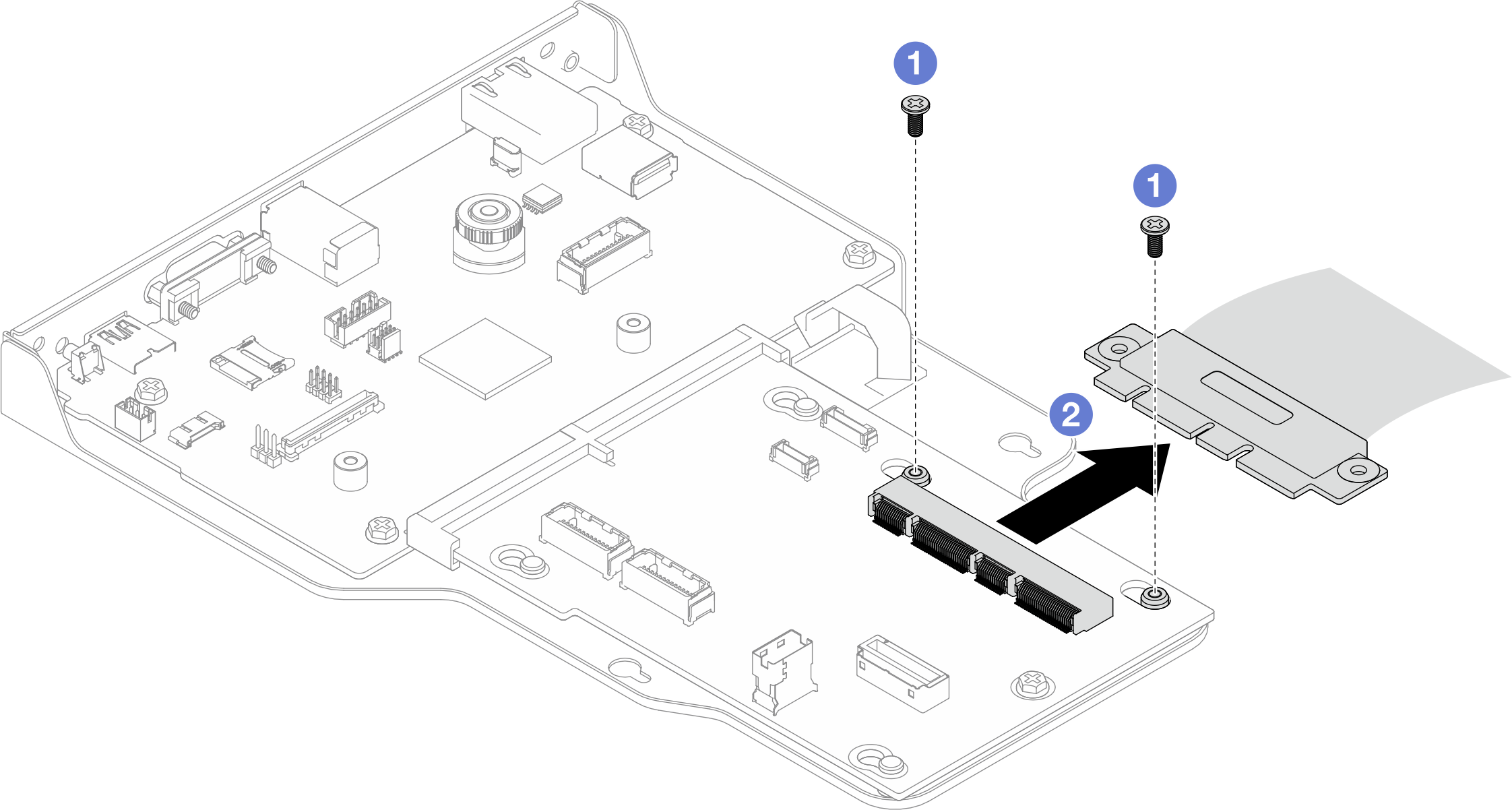
- Remove the interposer board.Figure 4. Removing interposer board
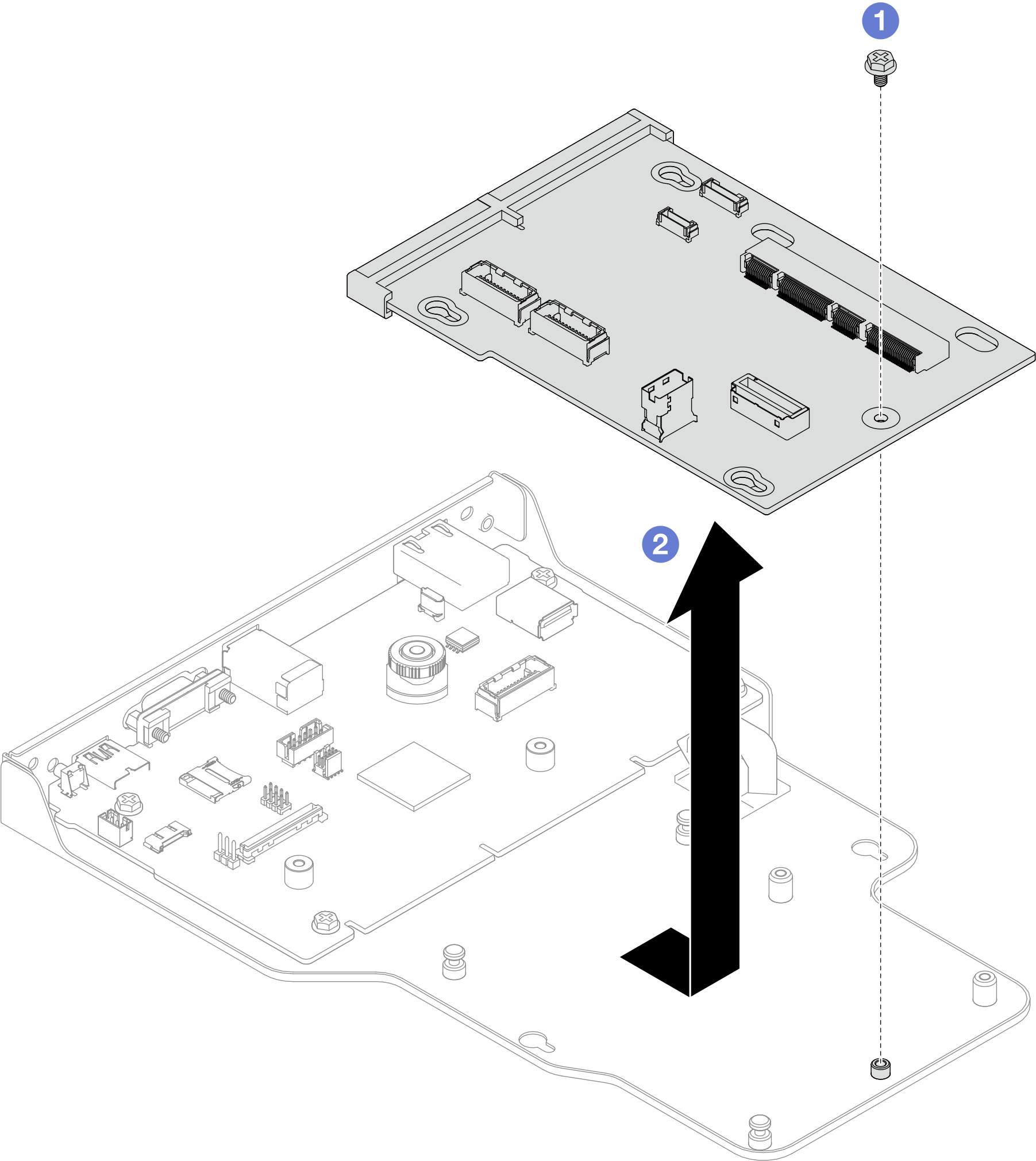
- Remove the screw that secure the interposer board.
- Hold the interposer board by its edges and slide it away from the system I/O board to remove it.
- Remove the system I/O board from the bracket.NoteTo prevent the contact of the system I/O board from damage, pinch and lift the plunger on the system I/O board upward a little and pull out the system I/O board outward. During the entire pulling action, ensure that the system I/O board remains as horizontal as possible.Figure 5. Removing system I/O board from bracket
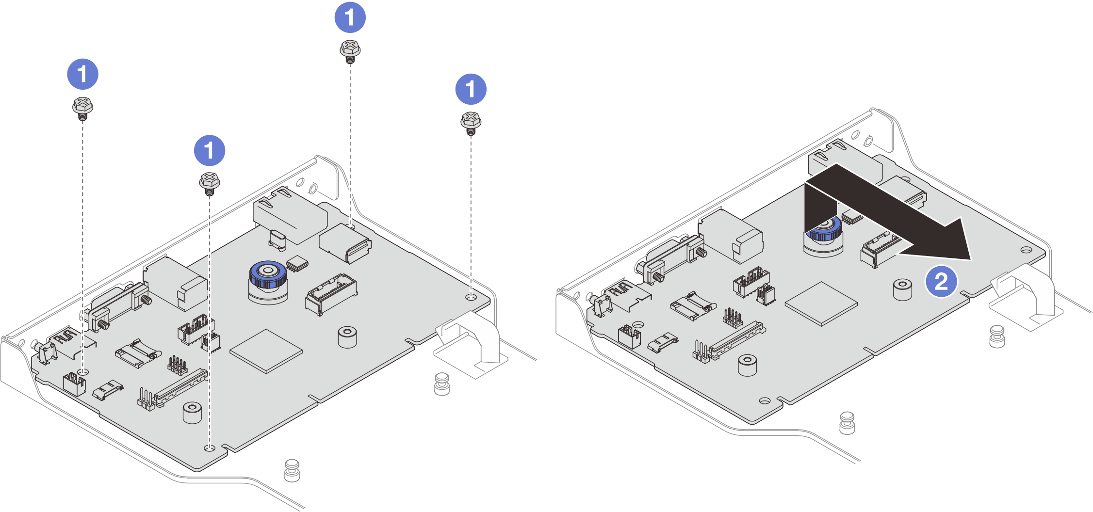
- Remove the four screws that secure the system I/O board.
- Lift and hold the plunger; then, slide the system I/O board away from the bracket to remove t.
After you finish
Install a replacement unit. See Install the system I/O board and interposer board.
If you are instructed to return the component or optional device, follow all packaging instructions, and use any packaging materials for shipping that are supplied to you.
Demo video