Install a hard disk drive backplane (lower tray)
Hard disk drive backplanes in the lower compute tray are accessed from the front of the server. There are several types of hard disk drive backplane. Steps that are backplane specific are noted in each procedure.

Before you install the hard disk drive backplane:
If the front cover is installed, remove it. See Remove the front cover.
Determine the location of the backplanes to be installed. Backplanes are installed in the following order:
For SAS-only drive backplanes, backplanes should be populated from left to right, when viewed from the front of the server (backplane for drives 0-3 first; then, 4-7 and 8-11).
For NVMe/SAS drive backplanes, backplanes should be populated from right to left, when viewed from the front of the server (backplane for drives 8-11 first; then, 4-7 and 0-3).
These population orders allow a mix of drive backplane types to be installed in the server.
Apply new drive-bay labels based on the backplane locations determined in the previous step. Several drive bay labels come with each type of the supported drive backplane. Install the labels that match the label types used for your server.
Remove the lower compute tray. See Remove a compute tray.
Remove the fan cage. See Remove a fan cage (lower tray).
Move or remove the storage interposer to access the hard disk drive backplanes. See Remove a storage interposer (lower tray).
If a hard disk drive backplane is already installed in this location:
After noting their locations, remove any hard disk drives that are installed in the lower compute tray. See Remove a hard disk drive.
Remove the hard disk drive backplane. See Remove a hard disk drive backplane (lower tray)
Move cables and harnesses to provide a clear path for accessing the hard disk drive backplanes and their connectors.
Complete the following steps to install a hard disk drive backplane in the lower compute tray.
- Install the hard disk drive backplane.NoteExisting cables might need to be removed from their retaining clips or moved to the side to install the backplane.Figure 1. Hard disk drive backplane (lower) installation
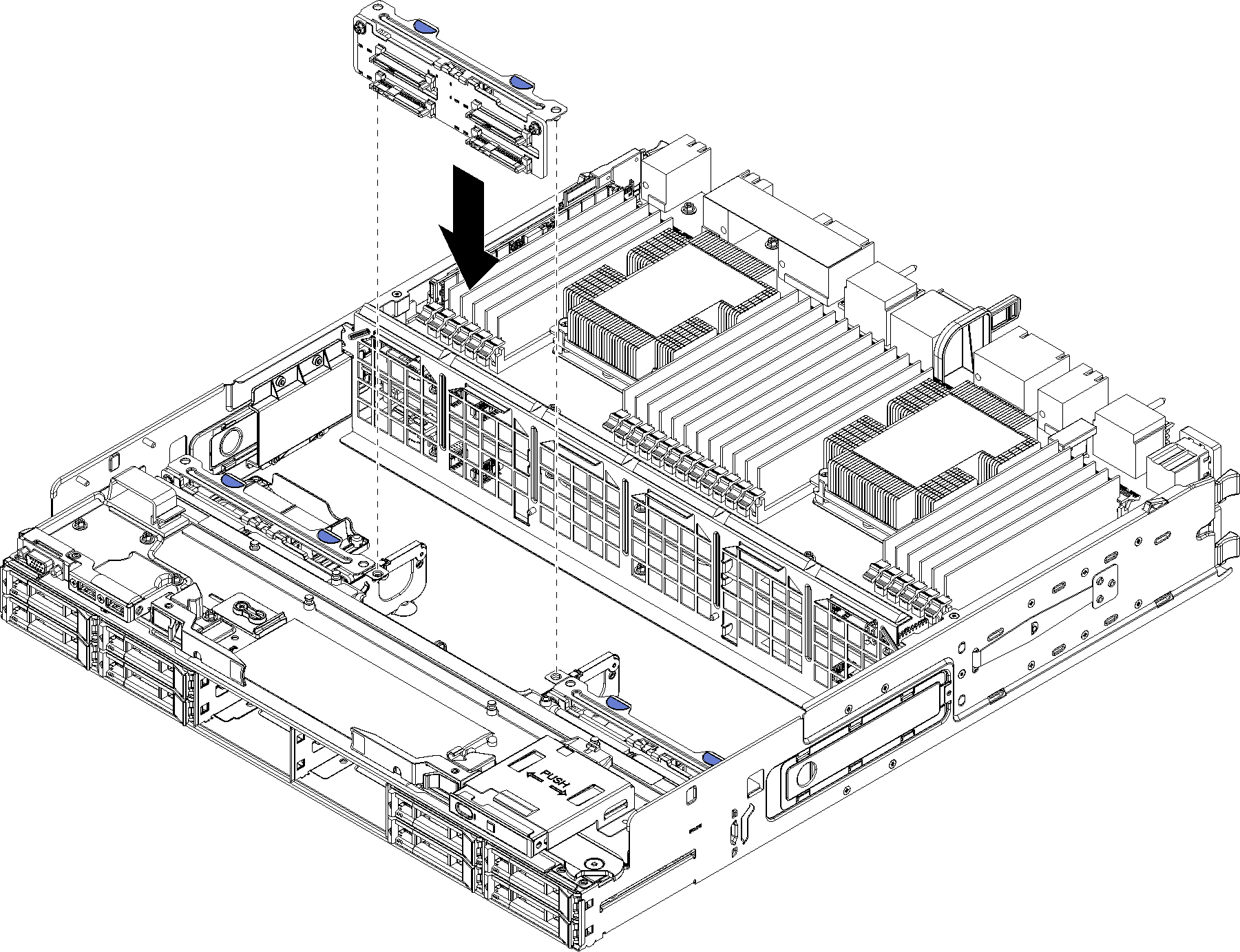
Align the backplane with its location in the server; then, insert the backplane and push it down until it is fully seated.
After you install the hard disk drive backplane:
Install the storage interposer and connect all cables. See Install a storage interposer (lower tray).
Make sure that all of the cables are correctly routed after they have been connected.
Install the fan cage. See Install a fan cage (lower tray).
If you have no additional options to install in the lower compute tray, install it into the chassis. See Install a compute tray.
Install any hard disk drives that you removed from the lower compute tray. Each drive should be installed in its original location. See Install a hard disk drive.
If you have no additional options to install in the upper or lower compute tray, install the front cover. See Install the front cover.
Demo video