Remove the processor board
Follow instructions in this section to remove the processor board.
About this task
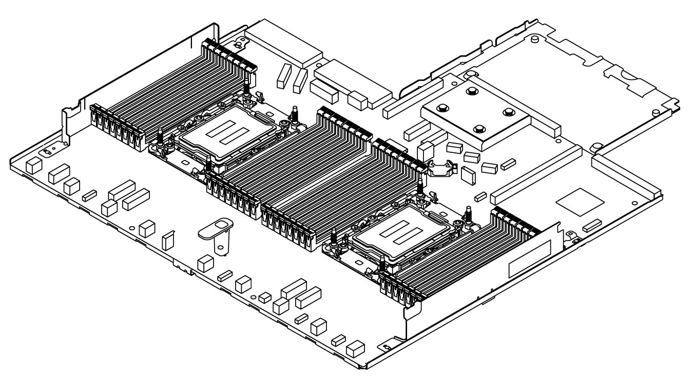
A processor board provides different connectors or slots to connect different components or peripherals of the system for communication. The board and the supporting metal sheet constitute a base for the system board assembly. If the processor board fails, it must be replaced.
This task must be operated by trained technicians that are certified by Lenovo Service. Do not attempt to remove or install the part without proper training and qualification.
When removing the memory modules, label the slot number on each memory module, remove all the memory modules from the system board assembly, and set them aside on a static-protective surface for reinstallation.
When disconnecting cables, make a list of each cable and record the connectors the cable is connected to, and use the record as a cabling checklist after installing the new system board assembly.
Read Installation Guidelines and Safety inspection checklist to ensure that you work safely.
Power off the server and peripheral devices and disconnect the power cords and all external cables. See Power off the server.
Prevent exposure to static electricity, which might lead to system halt and loss of data, by keeping static-sensitive components in their static-protective packages until installation, and handling these devices with an electrostatic-discharge wrist strap or other grounding systems.
Procedure
- Remove the system board assembly from the chassis.Figure 1. System board assembly removal
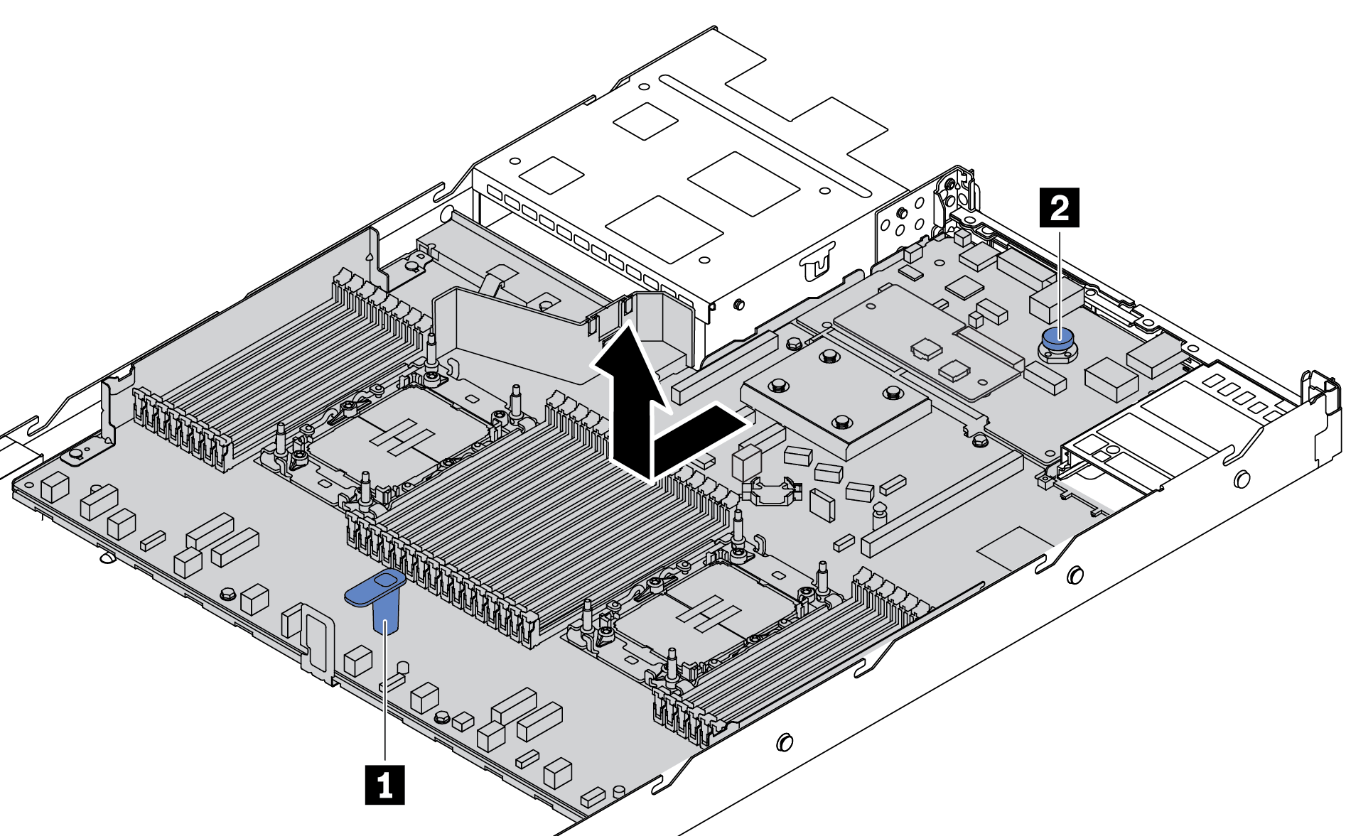
- Hold the lift handle 1 and lift the release pin 2 at the same time and slide the system board assembly toward the front of the server.
- Lift the system board assembly out of the chassis.
After you finish
Before you return the system board assembly, make sure that the processor socket is covered. There is a processor external cap covering the processor socket on the new system board assembly. Slide the processor external cap out from the processor socket on the new system board assembly, and install the external cap on the processor socket on the removed system board assembly.
If you are planning to recycle the system board assembly, follow the instructions in Hardware disassembling for recycle for compliance with local regulations.
Demo video