Replacing the operator information panel
Use this information to replace the operator information panel.
Note
The server configuration you have bought may either have the operator information panel inside the media cage or on the side of the server.
To install the operator information panel that is inside the media cage, complete the following steps:
- Read the safety information that begins in Safety and Installation guidelines.
- Touch the static-protective package that contains the operator information panel to any unpainted metal surface on the outside of the chassis; then, remove the operator information panel from the package.
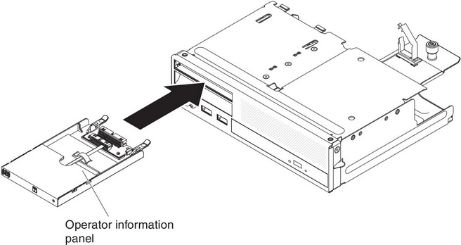
- From the front of the server, slide the operator information panel into the server until it stops.
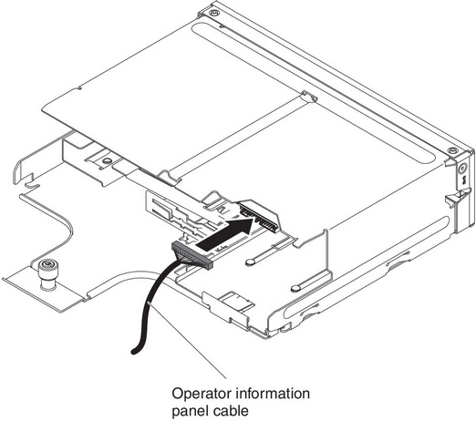
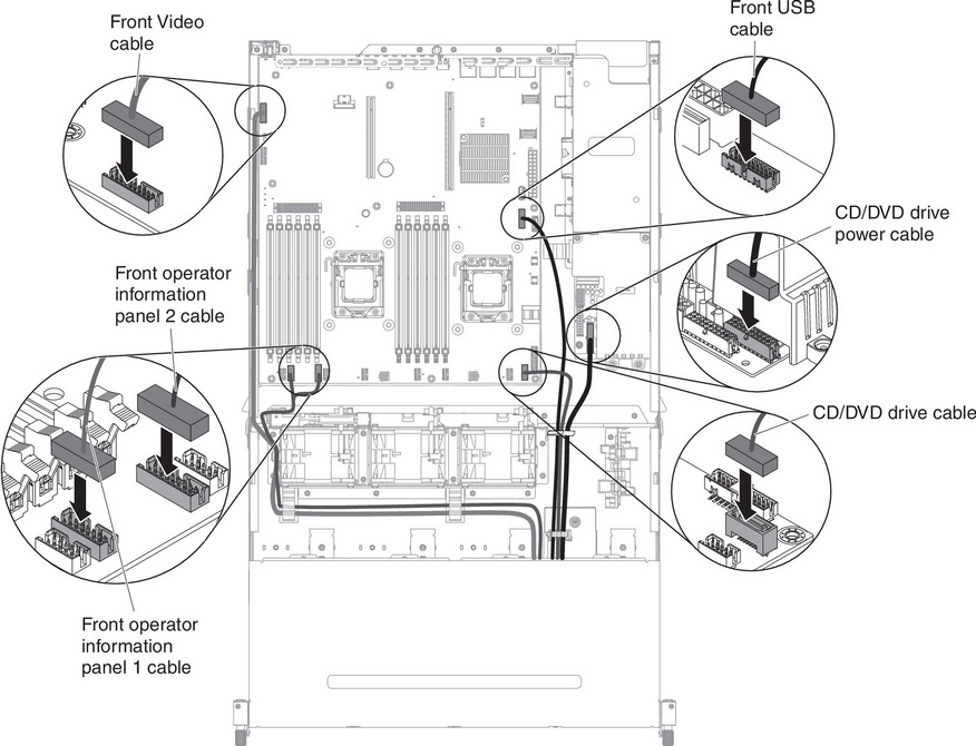
- Reconnect the cable to the operator information panel.
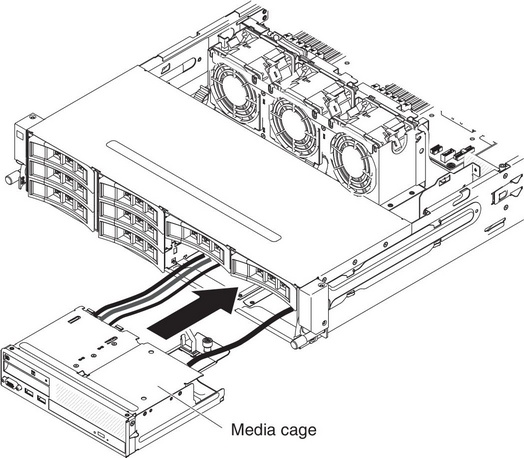
- Carefully push the media cage back into the server.
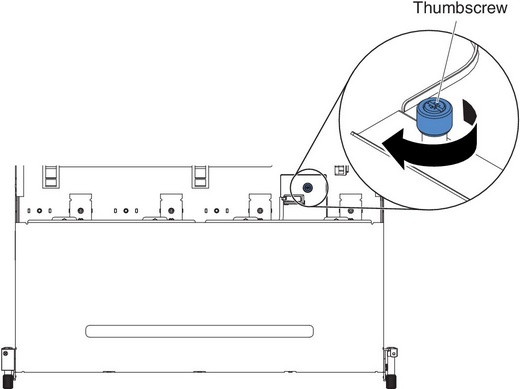
- Tighten the thumbscrew to secure the media cage onto the server.
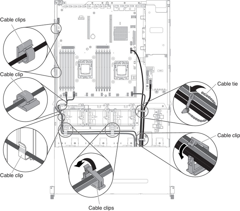
- Reconnect the USB, video, CD/DVD and operator information cables to the system board. Remember to insert the cables into the relevant cable clips and cable tie.
- Install the air baffle (see Replacing the air baffle).
- Install the PCI riser-card assembly (see Replacing a PCI riser-card assembly).
- Install the server top cover (see Replacing the server top cover).
- Reconnect the power cord and any cables that you removed.
- Turn on the peripheral devices and the server.
To install the operator information panel that is on the side of the server, complete the following steps:
- Touch the static-protective package that contains the operator information panel to any unpainted metal surface on the outside of the chassis; then, remove the operator information panel from the package.
- Reconnect the cable to the operator information panel.
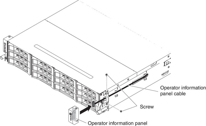
- Install the screws to secure the operator information panel to the side of the server.
- Slide the cable arm cover into the retention slots and install the screws to secure it on the side of the chassis.NoteThe cable is routed on the outside of the chassis and connected to the system board. The cable must be protected by the cable cover on the side of the chassis.
- Reconnect the external cables; then, reconnect the power cords and turn on the peripheral devices and the server.
Give documentation feedback