Install the system board
Follow instructions in this section to install the system board.

About this task
Removing and installing this component requires trained technicians. Do not attempt to remove or install the part without proper training.
Read Installation Guidelines and Safety inspection checklist to ensure that you work safely.
Power off the server and peripheral devices and disconnect the power cords and all external cables. See Power off the server.
Touch the static-protective package that contains the component to any unpainted metal surface on the server; then, remove it from the package and place it on a static-protective surface.
Go to Drivers and Software download website for ThinkEdge SE455 V3 to see the latest firmware and driver updates for your server.
Go to Update the firmware for more information on firmware updating tools.
Procedure
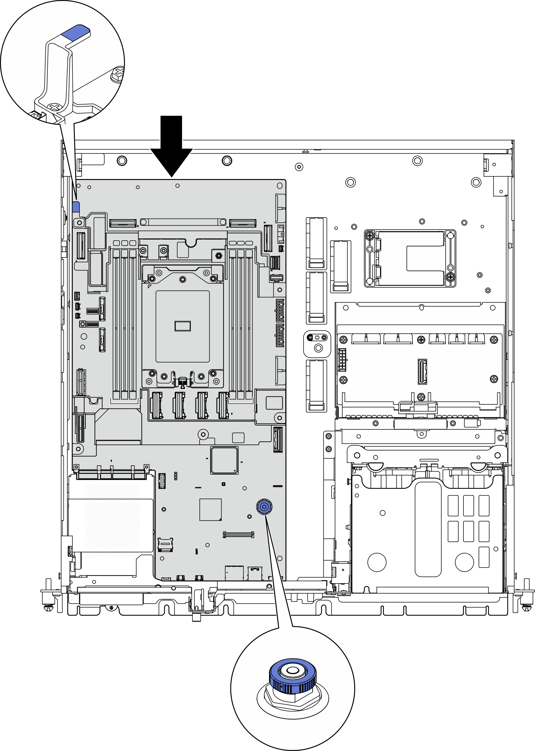
- Place the right end of the system board into the chassis; then, lower the left end of the system board into the chassis.NoteMake sure that the system board does not cover any cables in the chassis.Figure 1. Installing the system board

- Hold the handle and the plunger, and slide the system board slightly forward until it clicks into place.Figure 2. Securing the system board
- Peel away the XClarity Controller network access label on the processor socket cover, and attach it to the network access tag on the front of the server.Figure 3. Lenovo XClarity Controller network access label on the pull-out information tab

After this task is completed
Reinstall the processor and the heat sink. See Install a heat sink and Install a processor.
Reconnect all the required cables to the same connectors on the system board as the defective system board.
If applicable, reinstall the MicroSD card. See Install the MicroSD card.
Reinstall the firmware and RoT security module. See Install the firmware and RoT security module.
Reinstall all the memory modules. See Install a memory module.
If applicable, reinstall the air flow sensor board. See Install the air flow sensor board.
Reinstall the fan control board. See Install the fan control board (FCB).
Reinstall the fan cage. See Install the fan cage.
Reinstall all the fan modules. See Install a fan module.
Reinstall the intrusion switch. See Install the intrusion switch with cable.
Reinstall the processor air baffle. See Install the processor air baffle
Reinstall PCIe riser 1 and PCIe riser 2. See Install the PCIe riser assembly.
If applicable, reinstall the internal drive cage. See Install the internal drive cage.
If applicable, reinstall the internal drive backplane. See Install the internal drive backplane.
If applicable, reinstall all the internal drives. See Install an internal drive.
Ensure that all components have been reassembled correctly and that no tools or loose screws are left inside the server.
Reinstall the top cover. See Install the top cover.
If applicable, reinstall the OCP module. See Install the OCP module.
If the server was installed in a rack, reinstall the server into the rack. See Install the server to the rack.
Reconnect the power cords and any cables that you removed.
Reset the system date and time.
Update the vital product data (VPD). See Update the Vital Product Data (VPD).
Machine type number and serial number can be found on the ID label, see Identify the server and access the Lenovo XClarity Controller.
Update the UEFI, XCC and LXPM firmware to the specific version supported by the server. See Update the firmware.
If applicable, install Lenovo Features on Demand activation key. See the
License Management
section in the XCC documentation compatible with the server at Lenovo XClarity Controller portal page.Update the public key. See the
Update Device Key
section of ThinkShield Edge Mobile Management Application User Guide or ThinkShield Key Vault Portal Web Application User Guide in ThinkEdge Security for more details.Note- The role of Lenovo ID should be Maintenance User to update the public key in ThinkShield Key Vault Portal web interface or ThinkShield mobile app.
- (Lenovo service technician only) See How to update public key after system board replacement for the details.
If hiding TPM or updating TPM firmware is needed, see Hide/observe TPM or Update the TPM firmware.
Optionally, enable UEFI Secure Boot. See Enable UEFI Secure Boot.
Reconfigure the following ThinkEdge security features if necessary.
Change System Lockdown Control status to ThinkShield Portal. See Activate or unlock the system
Enable SED encryption. See Manage the Self Encryption Drive Authentication Key (SED AK).
Recover SED AK. See Manage the Self Encryption Drive Authentication Key (SED AK).
Enable security features. See System Lockdown Mode.
Change the emergency XCC password reset settings. See Emergency XCC Password Reset.
Demo Video