
Remove the system board

Follow instructions in this section to remove the system board.

S002
disconnect all power
CAUTION
The power-control button on the device and the power switch on the power supply do not turn off the electrical current supplied to the device. The device also might have more than one power cord. To remove all electrical current from the device, ensure that all power cords are disconnected from the power source.
S012
hot surface
CAUTION
Hot surface nearby.

About this task

Important
  • Removing and installing this component requires trained technicians. Do not attempt to remove or install the part without proper training.

  • When replacing the system board, always update the server with the latest firmware or restore the pre-existing firmware. Make sure that you have the latest firmware or a copy of the pre-existing firmware before you proceed.
  • When removing the memory modules, label the slot number on each memory module, remove all the memory modules from the system board, and set them aside on a static-protective surface for reinstallation.

  • When disconnecting cables, make a list of each cable and record the connectors the cable is connected to, and use the record as a cabling checklist after installing the new system board.

Attention

Procedure

  1. Make preparation for this task.
    1. Record all system configuration information, such as Lenovo XClarity Controller IP addresses, vital product data, and the machine type, model number, serial number, Universally Unique Identifier, and asset tag of the server.
    2. If SED encryption is enabled, maintain a backup of SED AK. See Manage the Self Encryption Drive Authentication Key (SED AK).
    3. If applicable, export Lenovo Features on Demand activation key. See the License Management section in the XCC documentation compatible with the server at Lenovo XClarity Controller portal page.
    4. Save the system configuration to an external device with Lenovo XClarity Essentials.
    5. Save the system event log to external media.
    6. If applicable, remove the OCP module. See Remove the OCP module.
    7. Remove the top cover. See Remove the top cover.
    8. If applicable, remove all the internal drives. See Remove an internal drive.
    9. If applicable, remove the internal drive backplane. See Remove the internal drive backplane.
    10. If applicable, remove internal drive cage. See Remove the internal drive cage.
    11. Remove all the PCIe assemblies. See Remove the PCIe riser assembly.
    12. Remove the processor air baffle. See Remove the processor air baffle.
    13. Remove the intrusion switch. See Remove the intrusion switch with cable.
    14. Remove all the fan modules. See Remove a fan module.
    15. Remove the fan cage. See Remove the fan cage.
    16. Remove the fan control board (FCB). See Remove the fan control board (FCB).
    17. If applicable, remove the air flow sensor board. See Remove the air flow sensor board.
    18. Make sure to label the slot number on each memory module, remove all the memory modules from the system board assembly, and set them aside on a static-protective surface for reinstallation. See Remove a memory module.
    19. Remove the firmware and RoT security module. See Remove the firmware and RoT security module.
    20. If applicable, remove the MicroSD card from the system board to install it onto the new system board. See Remove the MicroSD card.
    21. Remove the heat sink and the processor. See Remove a heat sink and Remove a processor.
  2. Disconnect all the cables from the system board. While disconnecting the cables, make a list of each cable and record the connectors the cable is connected to, and use the record as a cabling checklist after installing the new system board.
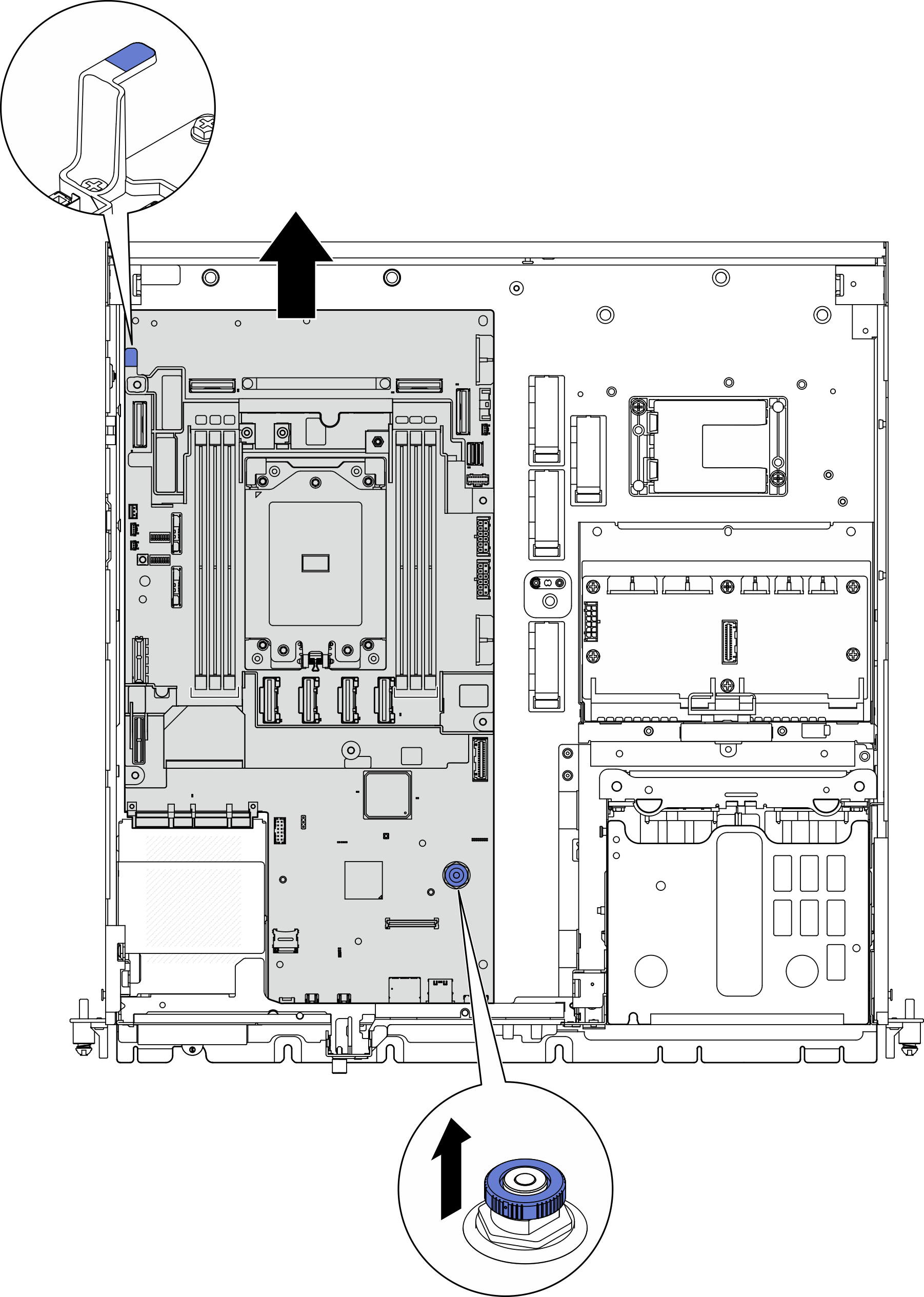
  3. Pull the plunger up; then, hold the plunger and the handle, and slide the system board slightly backward to disengage it from the chassis.
    Figure 1. Disengaging the system board

  4. Rotate the left end of the system board up to remove the system board from the chassis.
    Figure 2. Removing the system board

After this task is completed

  • Install a replacement unit. See Install the system board.

  • If you are instructed to return the component or optional device, follow all packaging instructions, and use any packaging materials for shipping that are supplied to you.

    Important
    Before you return the system board, make sure that you install the processor socket cover from the new system board. To replace a processor socket cover:
    1. Take a socket cover from the processor socket assembly on the new system board and orient it correctly above the processor socket assembly on the removed system board.

    2. Gently press down the socket cover legs to the processor socket assembly, pressing on the edges to avoid damage to the socket pins. You might hear a click on the socket cover is securely attached.

    3. Make sure that the socket cover is securely attached to the processor socket assembly.

  • If you plan to recycle the component, see Disassemble the system board for recycle.

Demo Video

Watch the procedure on YouTube